Microgrid Stability: Load, Fault Levels, Renewables Analysis Report
VerifiedAdded on 2023/06/14
|16
|3236
|468
Report
AI Summary
This report provides a comprehensive analysis of power system stability, focusing on demand-side management using microgrids, the role of virtual inertia in grids with high levels of renewables, and load and fault level analysis of a remote area microgrid. The demand-side management section explores load shifting strategies and customer pricing policies. The virtual inertia section discusses its importance in maintaining grid frequency and its implementation in wind, solar-PV, and battery storage feeders. The load and fault level analysis includes calculations of 3-phase fault levels under different scenarios, considering the impact of distributed generation and potential load shedding requirements. The report concludes with an examination of the advantages and disadvantages of pumped water storage compared to distributed battery storage for grid stability.

Power System Stability and Analysis 1
POWER SYSTEM STABILITY AND ANALYSIS
Students name
Class name
Tutors name
Institutional affiliation
City/state located
date
POWER SYSTEM STABILITY AND ANALYSIS
Students name
Class name
Tutors name
Institutional affiliation
City/state located
date
Paraphrase This Document
Need a fresh take? Get an instant paraphrase of this document with our AI Paraphraser

Power System Stability and Analysis 2
QUESTION 1: DEMEND SIDE MANAGEMENT
Part A
Analyzing the typical winter and summer electric power usage daily loads curves for NSW that was
provided;
I. The loads that were identified to be shifted or temporarily be avoided were; the wash
machine, dryer, pool pump, computers dish washer, hot water and air conditioning.
II. Those that could be shifted forward are hot water on demand, dish washer and the air
conditioning. Those that could be shifted backwards include the pool pump, dryer, wash
machine and computers.
III. Those loads that could be shifted backwards like the wash machine should be shifted for 4
hours as its maximum demand is at 2100 hours thus it can be shifted 4 hours back. The pool
pump should be shifted backwards 7 hours as its peak demand occurs at 2000 hours while at
1300 the power demand is low hence it should have been shifted 7 hours back.
IV. The customer pricing policy that could be required so that the suggested load shifting could
be possible is to give financial incentives to consumers who would use electrical energy when
the demand is low (off peak hours). Also, dual pricing policy is required. Where the devices
are categorized into those that can be interrupted and those that can’t be interrupted hence
varying with the shifted hours (Santosa, 2015).
Part B
The micro grid was used for demand side management purposes; it has a solar generation and battery
storage. Apart from that, a top up supply was required from the main supply.
The data provided;

Power System Stability and Analysis 3
Micro grid load: Group A 1000Kw/800Kw/400kw; Group B 1200kw/1000kw/500kw and Group C
1500KW/1200/600
Maximum load allowed by micro grid into the main grid; Group A 300KW/400KW/500KW; Group B
400KW/600KW/750KW and group C 500KW/800KW/1000KW
Micro grid load allocation tier 2(settable): total for groups A/B/C 600/800/1000KW for up to 8 hours;
remaining 400kw and it can be shed.
Analysis of The Different Cases
Case 0:
In this case all the situations were normal; all the solar resources were available and also the grid top-
up was available all day.
Battery was at 50%=50% of XkWh= 0.5Xkwh (assuming its storage capacity to be X)
To determine the combination of battery storage capacity and solar power rating that will supply all
loads in the micro grid and finish the day;
From the data provided; the total loads in a day;
peak = (1000+1200+1500) +(600 from tier 2) =4300;
in shoulder (800+1000+1200) + (800 from tier 2) = 3800;
and off peak (400+500+600) + (1000 form tier 2) =2500Kw
{total load = 4300+3800+2500=1060Kw}
In energy form; during peak 17200kWh, in shoulder 30400Kwh and during off peak 30000kWh.
hence total energy required in a day= 17200+ 30400+30000= 77600kWh
The battery started supplying the loads from the in-shoulder time; since only 80% of its capacity can
be used Hence only 0.4 X kWh (0.5 x 0.8) was available to supply the loads (de Almeida &
Rosenfeld, 2012).
⊘ This is a preview!⊘
Do you want full access?
Subscribe today to unlock all pages.

Trusted by 1+ million students worldwide

Power System Stability and Analysis 4
The main grid was allowed to supply some load and from the data provided the load it can be able to
supply are 300/400/500; Group B 400/600/750Kw and group C 500/800/1000; These totals to
1200/1800/2250;
Hence during the in-shoulder time; it provided 1800 kw(1800×8=14400kWh), during peak hours it
provided 1200 kw(1200×4=4800kWh) and during off peak it provided 2250 kw
(2250×12=27000kWh);
Since solar power was not available during the off-peak time; the remaining should be provided by
the battery (30000-27000=3000kWh)
Hence 0.4 X = 3000kWh; X= 7500kWh (its rating hence will be 7000kWh since it is the maximum
allowed capacity)
The rating of the solar can be obtained from the power it had to supply during the in-shoulder time
and also charger the battery to 50% of its storage capacity (Ziesemer, et al., 2012).
Power it had to supply was its rating (Y) x 4 hours during the in-shoulder hours; Y* 4 kWh and also
charge battery
The load remaining after the main grid has supplied during shoulder hours is; 30400-
14400=16000kWh. This should be supplied by the solar.
Hence Y*4= 16000+ X (rating of the battery) = 16000+7000= 23000kWh; Y= 23000/4=5750kWh;
718.75 kW
During peak hours the main grid supplies load of 4800kWh and hence the rest load during peak hours
need to be provided by the battery; (17200-4800= 12400kWh)
Hence total
Case 1:
Paraphrase This Document
Need a fresh take? Get an instant paraphrase of this document with our AI Paraphraser

Power System Stability and Analysis 5
Assume maximum load and solar output, but link to main grid failed. Unavailable during peak and
shoulder period.
Determination of any load shedding to be done.
Full load =77600kWh in a day;
The solar rating is 718.75 and it generated for four hours hence 718.75×4=2875kwh
And the battery will supply during the peak hours; 0.8×7000=5600kwh
The main grid will only provide to load during off-peak hours (27000kWh) from this, only load that
can be supplied is (2875+5600+27000=35475; hence the loads in tier 2 need to be shredded only
leaving the essential one only, which is 77600-35475=42125kWh and needs to be shredded (Al-enezi,
2010).
Case 2
Solar energy was only 70%= 2875×0.7=2012.5 kWh
Battery supply will be = 5600kWh (assuming it was fully charged)
Corresponding load is 95%= 77600×0.95=73720kWh
The main grid only supplies load during off-peak hours= 27000kWh
Hence total available for supply. = 2012.5+ 5600+ 27000=34612.5; hence shedding that need to be
done is; 73720- 34612.5=39107.5; essentially all the loads in tier 2 should be shredded off living only
the essential one (Dhole & Khedkar, 2010).
Case 3
Full load= 77600kWh
Solar output=2875kWh (full)
The battery =5600kWh
The main grid is assumed to have supplied 27000kWh during off peak hours before the emergency.

Power System Stability and Analysis 6
Hence total available= 5600+2875=8475kWh;
100× 12=1200kWh (requested to be injected to the main grid;)
Hence the energy available is 8475-1200+27000= 34275; the load shedding to be done; 77600-
34275=43325kWh (this shows all the loads in tier were shaded leaving only the essential ones)
Hence total available= 5600+2875=8475kWh;
100× 12=1200kWh (requested to be injected to the main grid;)
Hence the energy available is 8475-1200+27000= 34275; the load shedding to be done; 77600-
34275=43325kWh (this shows all the loads in tier were shaded leaving only the essential ones)
⊘ This is a preview!⊘
Do you want full access?
Subscribe today to unlock all pages.

Trusted by 1+ million students worldwide

Power System Stability and Analysis 7
QUESTION 2: THE ROLE OF VITUAL INERTIA IN GRIDS WITH HIGH LEVELS OF
RENEWABLES
1. There was no issue with the levels of rotating inertia in SA power grid during the system
black event. From the AEMO`s final report, what might have caused the blackout was
indicated to be damages to the lines of transmission (Australian Energy Market Operator,
2017). During the outrageous storm, there were pylons that were indicated to be
damaged. The automatic systems also disconnected the generators to protect them from
damage. Additionally, levels of rotating inertia could have contributed as well because
the wind farms reduced their production outputs like Hornsdale Wind Farm reduced
output by 86 MW. Low levels of rotating inertia could have led to much frequency
dynamics that resulted the Farms tripping and failing restart now and then. Rotating
inertia plays a major role in the grid; It helps determine and keep the frequency
deviations of the grid in manageable and acceptable ranges (Farkus & Pelcovitz, 2008).
2. Rotating inertia can be referred to as the lagging speed response of all synchro’s
generators and machines in an energy system in case of imbalance between power
generated and that demanded (Zhang, et al., 2016). and it can be implemented in wind
generators by; virtual inertia provided by externally rotating loads like pumps and fans
though these ones will not be efficient as they are connected also by frequency
converters. Can also be implemented using fast reacting generating systems.
3. The rotating inertia can be implemented in solar –PV and battery storage feeders by;
using storage units that will be providing synthetic inertia (Giakoumis & Rakopoulos,
2009).
Paraphrase This Document
Need a fresh take? Get an instant paraphrase of this document with our AI Paraphraser

Power System Stability and Analysis 8
4. Rotating inertia is a huge issue in micro grids. Moats of the micro grids are connected to
renewable sources of energy plants like PV- solar and wind. These have low rotational
inertia making it hard for the operation of the micro grid as it will be hard to deal with
frequency actuations (Katz, 2016). Also, the systems that can be used in place to provide
the synthetic inertia such as energy storage units are expensive making the micro grids
uneconomical too.
5. Pumped water storage is a mechanism employed to support the grid stability. Usually
they consist of reservoir such that during peak demand energy stored in hydraulic form
by lifting water from low level to high level is used to generate power like any
conventional hydro plant (Scherer & Stolten, 2013). It has its own advantages and
disadvantages when compared to distributed battery storage.
Advantages
i. In case it has been used in combination of thermal power plant, it can act as a
reservoir to cool other thermal units.
ii. Its complementary nature makes it to be economical than the other storage
mechanisms.
iii. Battery storage system can lead to reduction of rotating inertia of the system as it
has no rotating parts put in pumped storage the generators are synchronized to the
grid (Goswami, 2012).
Disadvantages
i. Can also be used where a water reservoir is available and reliable hence cannot be
integrated in other power farms like the solar and wind.

Power System Stability and Analysis 9
ii. Distributed battery have fast generation of power that the pumped storage as it
takes time for the generators to regain torque in case of power imbalances in the
grid.
ii. Distributed battery have fast generation of power that the pumped storage as it
takes time for the generators to regain torque in case of power imbalances in the
grid.
⊘ This is a preview!⊘
Do you want full access?
Subscribe today to unlock all pages.

Trusted by 1+ million students worldwide

Power System Stability and Analysis 10
QUESTION 3: LOAD AND FAULT LEVELS ANALYSIS OF REMOTE AREA
MICROGRID
From the data that was provided;
Line segments: line from Bus 1 to bus 2: 1km of impedance 0.27+j0.31 ohms/km; line from
Bus 2 to 3: 10 km of impedance = Group A 0.38+ j0.32, Group B 0.475+ j0.40, Group C
0.57+j0.48 ohms/km; each arm of the remote microgram ring (from 3 to 4): 1 km of
impedance = Group A 0.38+j0.32, Group B 0.475 + j0.40, Group C 0.57+ j0.48 ohms/km;
The negative sequence impedances= positive sequence impedance
The zero sequence impedances = 2.5 times the positive sequence
Line loading: line from Bus 1 to Bus 2 Group A 1000Kva, group B 1250, group C 1500; line
from Bus 2 to Bus 3: 500/625/750 and line from bus 3 to 4 total from each arm of the micro
grid 1000/1250/1500 kVA; all the loads are lagging by 0.9 PF
Peak output= peak load for the DGs.
The system protection: overcurrent relays are provided at CB3, CH4 and both CB1`s.
The following analysis was done.
1. Calculation of the 3-phase fault levels on Bus 2, Bus 3 and Bus 4 with the main
supply connected but the DGs disconnected.
Generally, the micro grid fault behavior is usually analyzed by using circuit analysis
(Sivanagaraju & Rami Reddy, 2007)approach where the equivalent phase coordinate
representation of the network is constructed. It can be represented by its equivalent
Bus impedance matrix. For the 3- phase faults, the only requirements are positive
Paraphrase This Document
Need a fresh take? Get an instant paraphrase of this document with our AI Paraphraser
Power System Stability and Analysis 11
sequence bus impedance matrix and only a positive sequence network (Glisson,
2011).
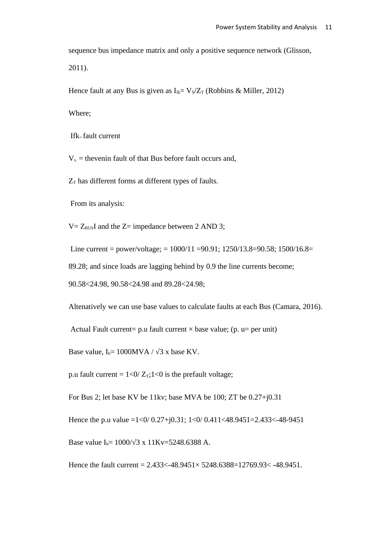
Hence fault at any Bus is given as Ifk= VS/ZT (Robbins & Miller, 2012)
Where;
Ifk= fault current
Vs. = thevenin fault of that Bus before fault occurs and,
ZT has different forms at different types of faults.
From its analysis:
V= ZBUSI and the Z= impedance between 2 AND 3;
Line current = power/voltage; = 1000/11 =90.91; 1250/13.8=90.58; 1500/16.8=
89.28; and since loads are lagging behind by 0.9 the line currents become;
90.58<24.98, 90.58<24.98 and 89.28<24.98;
Altenatively we can use base values to calculate faults at each Bus (Camara, 2016).
Actual Fault current= p.u fault current × base value; (p. u= per unit)
Base value, Ib= 1000MVA / √3 x base KV.
p.u fault current = 1<0/ ZT;1<0 is the prefault voltage;
For Bus 2; let base KV be 11kv; base MVA be 100; ZT be 0.27+j0.31
Hence the p.u value =1<0/ 0.27+j0.31; 1<0/ 0.411<48.9451=2.433<-48-9451
Base value Ib= 1000/√3 x 11Kv=5248.6388 A.
Hence the fault current = 2.433<-48.9451× 5248.6388=12769.93< -48.9451.
Power System Stability and Analysis 12
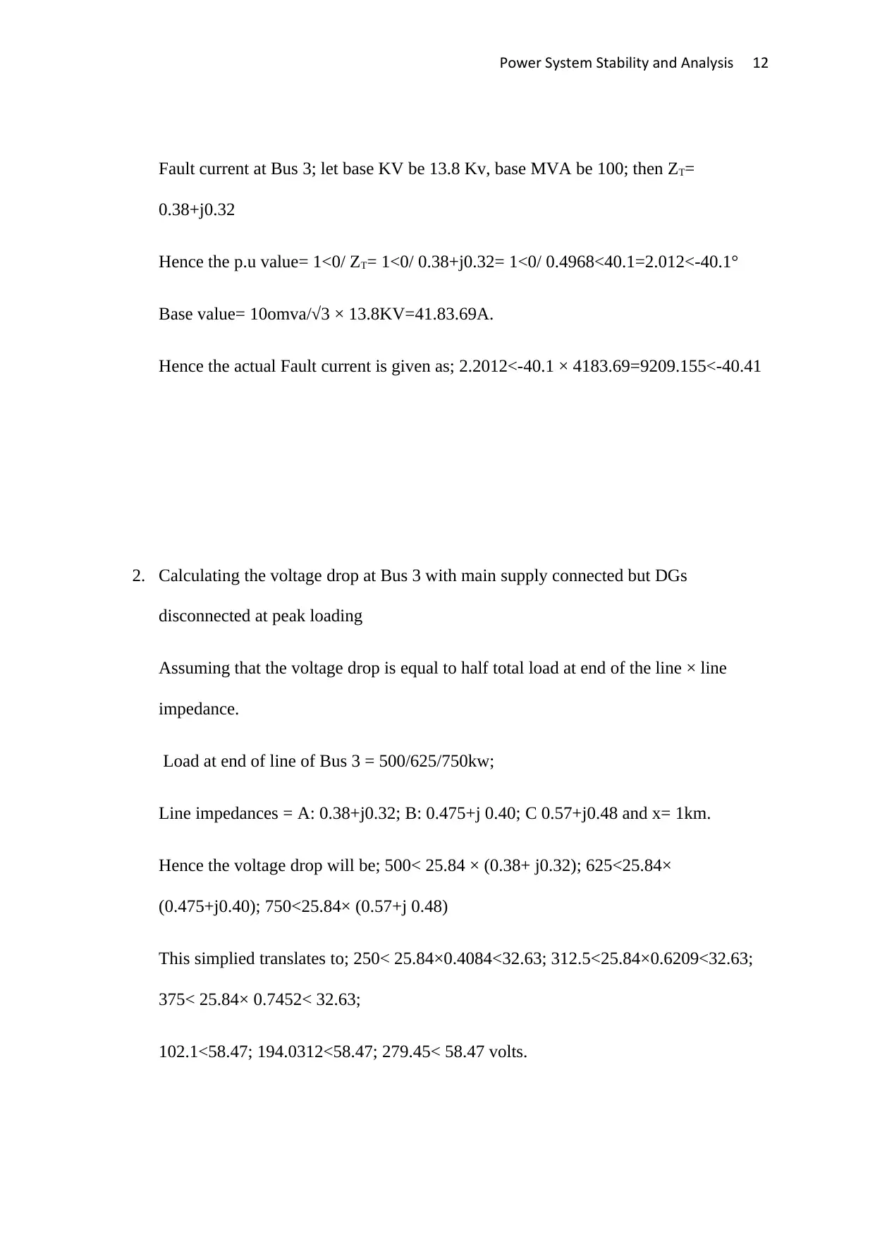
Fault current at Bus 3; let base KV be 13.8 Kv, base MVA be 100; then ZT=
0.38+j0.32
Hence the p.u value= 1<0/ ZT= 1<0/ 0.38+j0.32= 1<0/ 0.4968<40.1=2.012<-40.1°
Base value= 10omva/√3 × 13.8KV=41.83.69A.
Hence the actual Fault current is given as; 2.2012<-40.1 × 4183.69=9209.155<-40.41
2. Calculating the voltage drop at Bus 3 with main supply connected but DGs
disconnected at peak loading
Assuming that the voltage drop is equal to half total load at end of the line × line
impedance.
Load at end of line of Bus 3 = 500/625/750kw;
Line impedances = A: 0.38+j0.32; B: 0.475+j 0.40; C 0.57+j0.48 and x= 1km.
Hence the voltage drop will be; 500< 25.84 × (0.38+ j0.32); 625<25.84×
(0.475+j0.40); 750<25.84× (0.57+j 0.48)
This simplied translates to; 250< 25.84×0.4084<32.63; 312.5<25.84×0.6209<32.63;
375< 25.84× 0.7452< 32.63;
102.1<58.47; 194.0312<58.47; 279.45< 58.47 volts.
⊘ This is a preview!⊘
Do you want full access?
Subscribe today to unlock all pages.

Trusted by 1+ million students worldwide
1 out of 16
Your All-in-One AI-Powered Toolkit for Academic Success.
+13062052269
info@desklib.com
Available 24*7 on WhatsApp / Email
![[object Object]](/_next/static/media/star-bottom.7253800d.svg)
Unlock your academic potential
Copyright © 2020–2026 A2Z Services. All Rights Reserved. Developed and managed by ZUCOL.