Electronic Circuits: Power Supply and DAC Testing and Troubleshooting
VerifiedAdded on 2022/11/29
|10
|2317
|398
Report
AI Summary
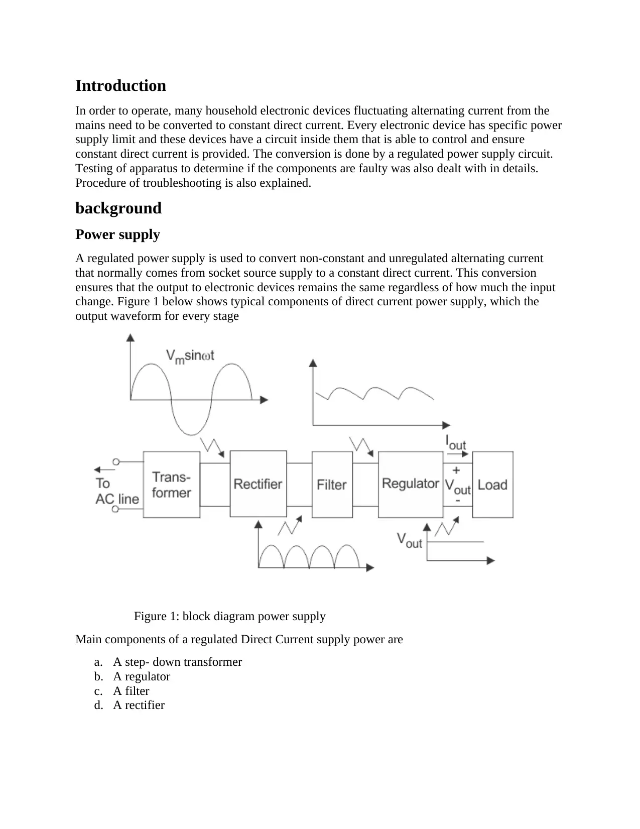
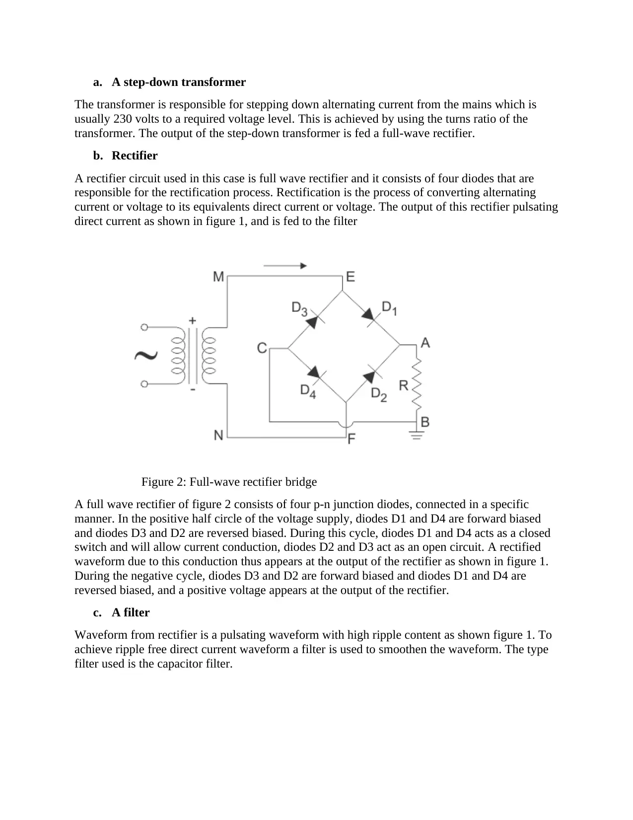
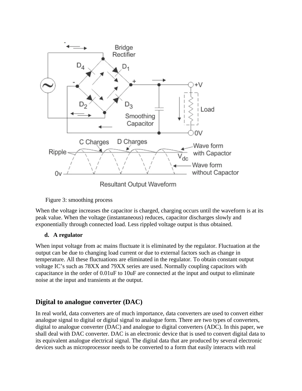
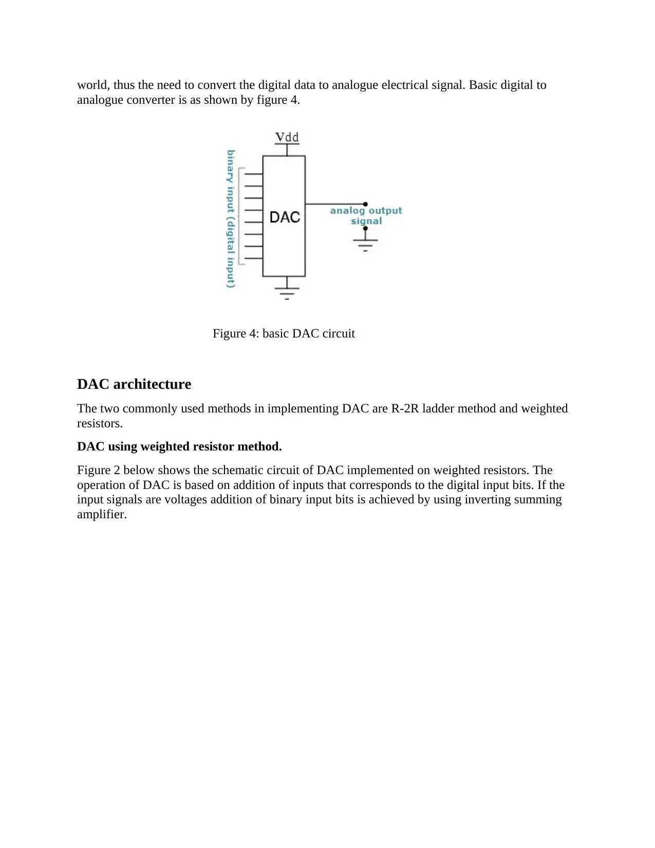
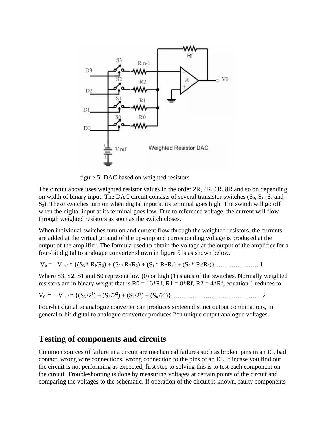
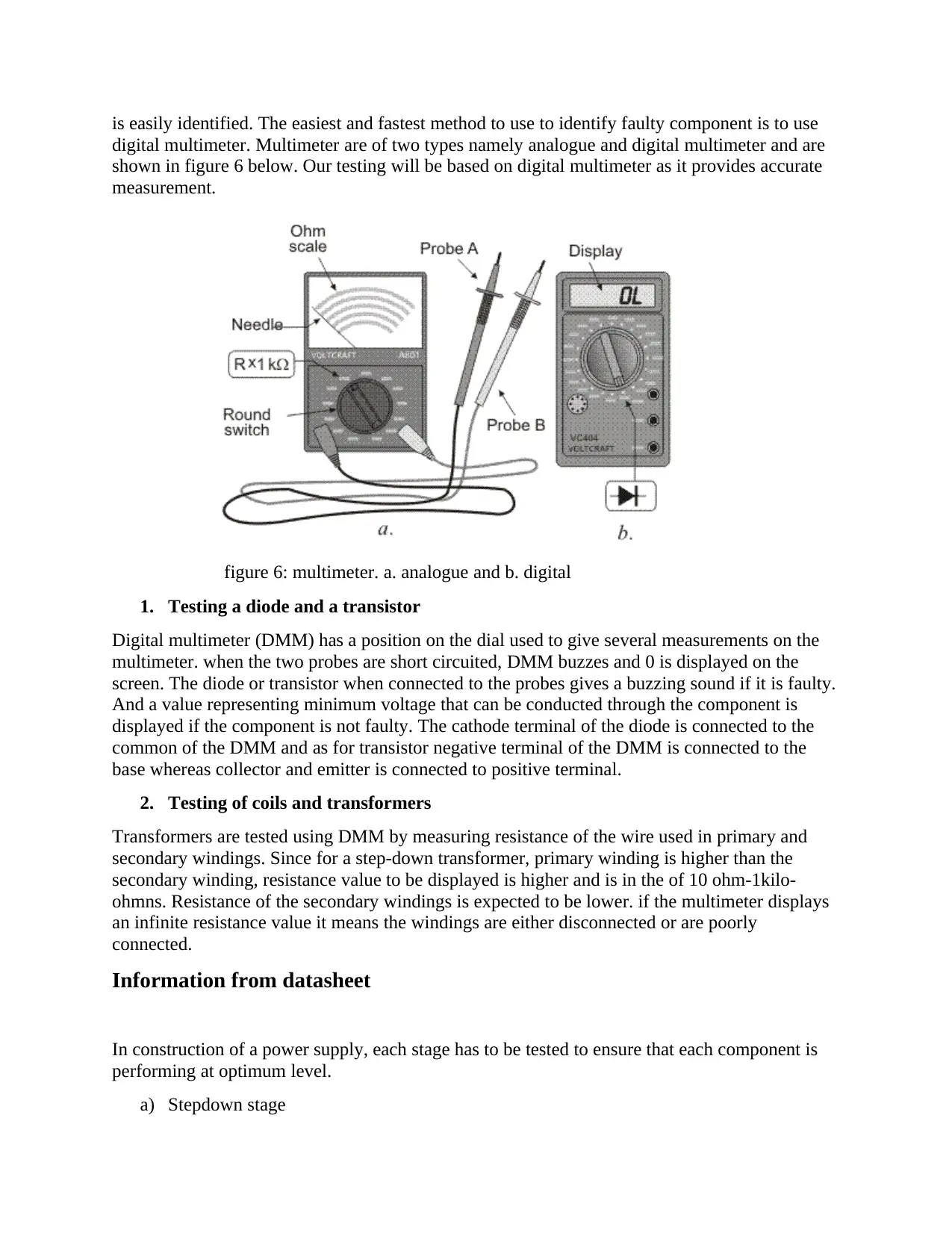
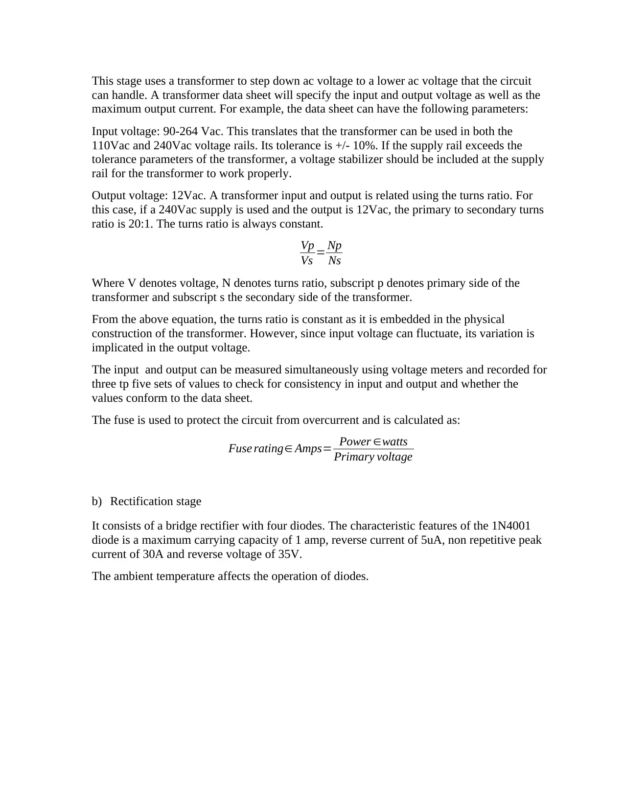
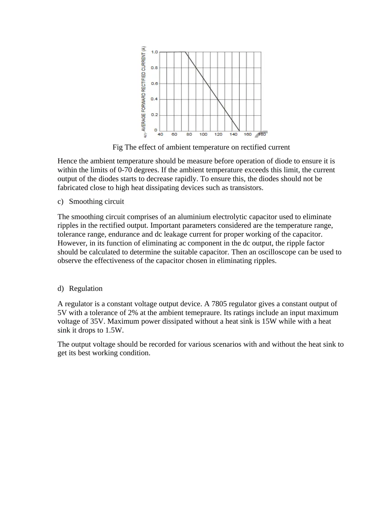
This report delves into the operation and testing of power supply and Digital-to-Analogue Converter (DAC) circuits. It begins with an overview of regulated power supplies, detailing the function of key components like transformers, rectifiers, filters, and regulators. The report then explains the working principles and architectures of DACs, including weighted resistor methods, and provides the relevant formulas. A significant portion of the report focuses on the testing of electronic components and circuits, including diodes, transistors, coils, and transformers, using digital multimeters. It also covers the interpretation of datasheets and the importance of parameters such as temperature, voltage, and current ratings. The report concludes with a discussion on troubleshooting techniques, highlighting common failure sources and procedures to identify faulty components. It includes information about the impact of ambient temperature on diodes and the application of oscilloscopes for ripple analysis in smoothing circuits, providing a comprehensive guide to power supply and DAC circuit analysis and testing.

Introduction
In order to operate, many household electronic devices fluctuating alternating current from the
mains need to be converted to constant direct current. Every electronic device has specific power
supply limit and these devices have a circuit inside them that is able to control and ensure
constant direct current is provided. The conversion is done by a regulated power supply circuit.
Testing of apparatus to determine if the components are faulty was also dealt with in details.
Procedure of troubleshooting is also explained.
background
Power supply
A regulated power supply is used to convert non-constant and unregulated alternating current
that normally comes from socket source supply to a constant direct current. This conversion
ensures that the output to electronic devices remains the same regardless of how much the input
change. Figure 1 below shows typical components of direct current power supply, which the
output waveform for every stage
Figure 1: block diagram power supply
Main components of a regulated Direct Current supply power are
a. A step- down transformer
b. A regulator
c. A filter
d. A rectifier
Paraphrase This Document
Need a fresh take? Get an instant paraphrase of this document with our AI Paraphraser

a. A step-down transformer
The transformer is responsible for stepping down alternating current from the mains which is
usually 230 volts to a required voltage level. This is achieved by using the turns ratio of the
transformer. The output of the step-down transformer is fed a full-wave rectifier.
b. Rectifier
A rectifier circuit used in this case is full wave rectifier and it consists of four diodes that are
responsible for the rectification process. Rectification is the process of converting alternating
current or voltage to its equivalents direct current or voltage. The output of this rectifier pulsating
direct current as shown in figure 1, and is fed to the filter
Figure 2: Full-wave rectifier bridge
A full wave rectifier of figure 2 consists of four p-n junction diodes, connected in a specific
manner. In the positive half circle of the voltage supply, diodes D1 and D4 are forward biased
and diodes D3 and D2 are reversed biased. During this cycle, diodes D1 and D4 acts as a closed
switch and will allow current conduction, diodes D2 and D3 act as an open circuit. A rectified
waveform due to this conduction thus appears at the output of the rectifier as shown in figure 1.
During the negative cycle, diodes D3 and D2 are forward biased and diodes D1 and D4 are
reversed biased, and a positive voltage appears at the output of the rectifier.
c. A filter
Waveform from rectifier is a pulsating waveform with high ripple content as shown figure 1. To
achieve ripple free direct current waveform a filter is used to smoothen the waveform. The type
filter used is the capacitor filter.

Figure 3: smoothing process
When the voltage increases the capacitor is charged, charging occurs until the waveform is at its
peak value. When the voltage (instantaneous) reduces, capacitor discharges slowly and
exponentially through connected load. Less rippled voltage output is thus obtained.
d. A regulator
When input voltage from ac mains fluctuate it is eliminated by the regulator. Fluctuation at the
output can be due to changing load current or due to external factors such as change in
temperature. All these fluctuations are eliminated in the regulator. To obtain constant output
voltage IC’s such as 78XX and 79XX series are used. Normally coupling capacitors with
capacitance in the order of 0.01uF to 10uF are connected at the input and output to eliminate
noise at the input and transients at the output.
Digital to analogue converter (DAC)
In real world, data converters are of much importance, data converters are used to convert either
analogue signal to digital or digital signal to analogue form. There are two types of converters,
digital to analogue converter (DAC) and analogue to digital converters (ADC). In this paper, we
shall deal with DAC converter. DAC is an electronic device that is used to convert digital data to
its equivalent analogue electrical signal. The digital data that are produced by several electronic
devices such as microprocessor needs to be converted to a form that easily interacts with real
⊘ This is a preview!⊘
Do you want full access?
Subscribe today to unlock all pages.

Trusted by 1+ million students worldwide

world, thus the need to convert the digital data to analogue electrical signal. Basic digital to
analogue converter is as shown by figure 4.
Figure 4: basic DAC circuit
DAC architecture
The two commonly used methods in implementing DAC are R-2R ladder method and weighted
resistors.
DAC using weighted resistor method.
Figure 2 below shows the schematic circuit of DAC implemented on weighted resistors. The
operation of DAC is based on addition of inputs that corresponds to the digital input bits. If the
input signals are voltages addition of binary input bits is achieved by using inverting summing
amplifier.
Paraphrase This Document
Need a fresh take? Get an instant paraphrase of this document with our AI Paraphraser

figure 5: DAC based on weighted resistors
The circuit above uses weighted resistor values in the order 2R, 4R, 6R, 8R and so on depending
on width of binary input. The DAC circuit consists of several transistor switches (S0, S1, 3S2 and
S3). These switches turn on when digital input at its terminal goes high. The switch will go off
when the digital input at its terminal goes low. Due to reference voltage, the current will flow
through weighted resistors as soon as the switch closes.
When individual switches turn on and current flow through the weighted resistors, the currents
are added at the virtual ground of the op-amp and corresponding voltage is produced at the
output of the amplifier. The formula used to obtain the voltage at the output of the amplifier for a
four-bit digital to analogue converter shown in figure 5 is as shown below.
V0 = - V ref * {(S3 * Rf/R3) + (S2 * Rf/R2) + (S1 * Rf/R1) + (S0 * Rf/R0)} ……………….. 1
Where S3, S2, S1 and S0 represent low (0) or high (1) status of the switches. Normally weighted
resistors are in binary weight that is R0 = 16*Rf, R1 = 8*Rf, R2 = 4*Rf, equation 1 reduces to
V0 = - V ref * {(S3 /21) + (S2 /22) + (S1/23) + (S0 /24)}…………………………………….2
Four-bit digital to analogue converter can produces sixteen distinct output combinations, in
general n-bit digital to analogue converter produces 2^n unique output analogue voltages.
Testing of components and circuits
Common sources of failure in a circuit are mechanical failures such as broken pins in an IC, bad
contact, wrong wire connections, wrong connection to the pins of an IC. If incase you find out
the circuit is not performing as expected, first step to solving this is to test each component on
the circuit. Troubleshooting is done by measuring voltages at certain points of the circuit and
comparing the voltages to the schematic. If operation of the circuit is known, faulty components

is easily identified. The easiest and fastest method to use to identify faulty component is to use
digital multimeter. Multimeter are of two types namely analogue and digital multimeter and are
shown in figure 6 below. Our testing will be based on digital multimeter as it provides accurate
measurement.
figure 6: multimeter. a. analogue and b. digital
1. Testing a diode and a transistor
Digital multimeter (DMM) has a position on the dial used to give several measurements on the
multimeter. when the two probes are short circuited, DMM buzzes and 0 is displayed on the
screen. The diode or transistor when connected to the probes gives a buzzing sound if it is faulty.
And a value representing minimum voltage that can be conducted through the component is
displayed if the component is not faulty. The cathode terminal of the diode is connected to the
common of the DMM and as for transistor negative terminal of the DMM is connected to the
base whereas collector and emitter is connected to positive terminal.
2. Testing of coils and transformers
Transformers are tested using DMM by measuring resistance of the wire used in primary and
secondary windings. Since for a step-down transformer, primary winding is higher than the
secondary winding, resistance value to be displayed is higher and is in the of 10 ohm-1kilo-
ohmns. Resistance of the secondary windings is expected to be lower. if the multimeter displays
an infinite resistance value it means the windings are either disconnected or are poorly
connected.
Information from datasheet
In construction of a power supply, each stage has to be tested to ensure that each component is
performing at optimum level.
a) Stepdown stage
⊘ This is a preview!⊘
Do you want full access?
Subscribe today to unlock all pages.

Trusted by 1+ million students worldwide

This stage uses a transformer to step down ac voltage to a lower ac voltage that the circuit
can handle. A transformer data sheet will specify the input and output voltage as well as the
maximum output current. For example, the data sheet can have the following parameters:
Input voltage: 90-264 Vac. This translates that the transformer can be used in both the
110Vac and 240Vac voltage rails. Its tolerance is +/- 10%. If the supply rail exceeds the
tolerance parameters of the transformer, a voltage stabilizer should be included at the supply
rail for the transformer to work properly.
Output voltage: 12Vac. A transformer input and output is related using the turns ratio. For
this case, if a 240Vac supply is used and the output is 12Vac, the primary to secondary turns
ratio is 20:1. The turns ratio is always constant.
Vp
Vs = Np
Ns
Where V denotes voltage, N denotes turns ratio, subscript p denotes primary side of the
transformer and subscript s the secondary side of the transformer.
From the above equation, the turns ratio is constant as it is embedded in the physical
construction of the transformer. However, since input voltage can fluctuate, its variation is
implicated in the output voltage.
The input and output can be measured simultaneously using voltage meters and recorded for
three tp five sets of values to check for consistency in input and output and whether the
values conform to the data sheet.
The fuse is used to protect the circuit from overcurrent and is calculated as:
Fuse rating∈ Amps= Power ∈watts
Primary voltage
b) Rectification stage
It consists of a bridge rectifier with four diodes. The characteristic features of the 1N4001
diode is a maximum carrying capacity of 1 amp, reverse current of 5uA, non repetitive peak
current of 30A and reverse voltage of 35V.
The ambient temperature affects the operation of diodes.
Paraphrase This Document
Need a fresh take? Get an instant paraphrase of this document with our AI Paraphraser

Fig The effect of ambient temperature on rectified current
Hence the ambient temperature should be measure before operation of diode to ensure it is
within the limits of 0-70 degrees. If the ambient temperature exceeds this limit, the current
output of the diodes starts to decrease rapidly. To ensure this, the diodes should not be
fabricated close to high heat dissipating devices such as transistors.
c) Smoothing circuit
The smoothing circuit comprises of an aluminium electrolytic capacitor used to eliminate
ripples in the rectified output. Important parameters considered are the temperature range,
tolerance range, endurance and dc leakage current for proper working of the capacitor.
However, in its function of eliminating ac component in the dc output, the ripple factor
should be calculated to determine the suitable capacitor. Then an oscilloscope can be used to
observe the effectiveness of the capacitor chosen in eliminating ripples.
d) Regulation
A regulator is a constant voltage output device. A 7805 regulator gives a constant output of
5V with a tolerance of 2% at the ambient temepraure. Its ratings include an input maximum
voltage of 35V. Maximum power dissipated without a heat sink is 15W while with a heat
sink it drops to 1.5W.
The output voltage should be recorded for various scenarios with and without the heat sink to
get its best working condition.

Conclusion
Operation and components that make DAC and power supply was discussed in the paper, Test
procedures are also handled, how to measure if a component is faulty or not using digital
multimeter. steps of how to troubleshoot a circuit that fails to perform as expected is also
discussed. And finally, information that is normally provided in the data sheet along-side the
equipment is analyzed
⊘ This is a preview!⊘
Do you want full access?
Subscribe today to unlock all pages.

Trusted by 1+ million students worldwide

REFERENCES
Boylestad, R.L. and Nashelsky, L. (2013) Electronic Devices and Circuit Theory.
11th Ed. Pearson.
Floyd, T.L. and Buchla, D. (2013) Electronics Fundamentals: Circuits, Devices &
Applications. 8th Ed. Pearson.
Horowitz, P. and Hill, W. (2015) The Art of Electronics. 3rd Ed. Cambridge
University Press
Tour, J.M., (2018). Molecular electronics. Synthesis and testing of components. Accounts of
Chemical Research, 33(11), pp.791-804.
Lo, Y., Mendell, N.R. and Rubin, D.B., 2001. Testing the number of components in a normal
mixture. Biometrika, 88(3), pp.767-778.
1 out of 10
Related Documents

Your All-in-One AI-Powered Toolkit for Academic Success.
+13062052269
info@desklib.com
Available 24*7 on WhatsApp / Email
Unlock your academic potential
Copyright © 2020–2025 A2Z Services. All Rights Reserved. Developed and managed by ZUCOL.