ELE1502 Electronic Circuits Assignment 2: Circuit Analysis and Testing

Verified

Added on  2023/03/23

|4
|525
|20
Homework Assignment
AI Summary
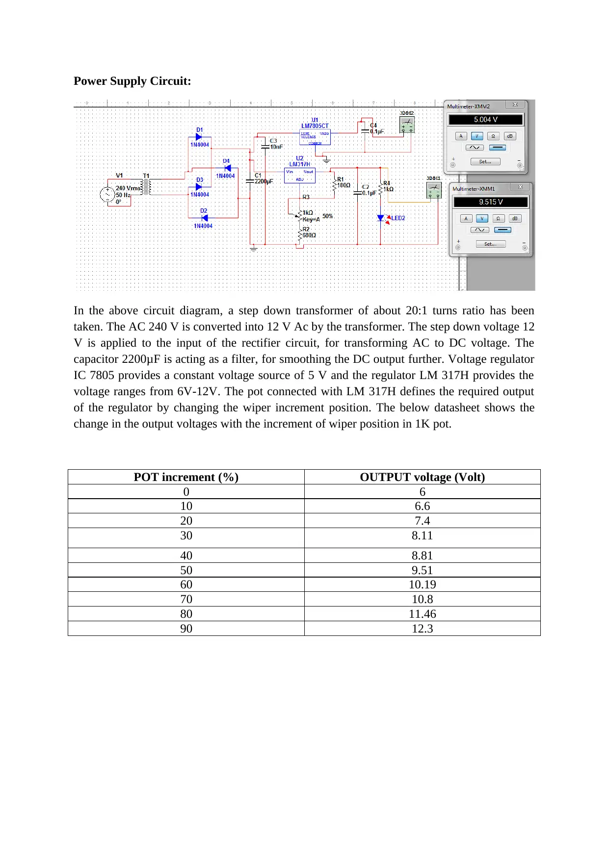
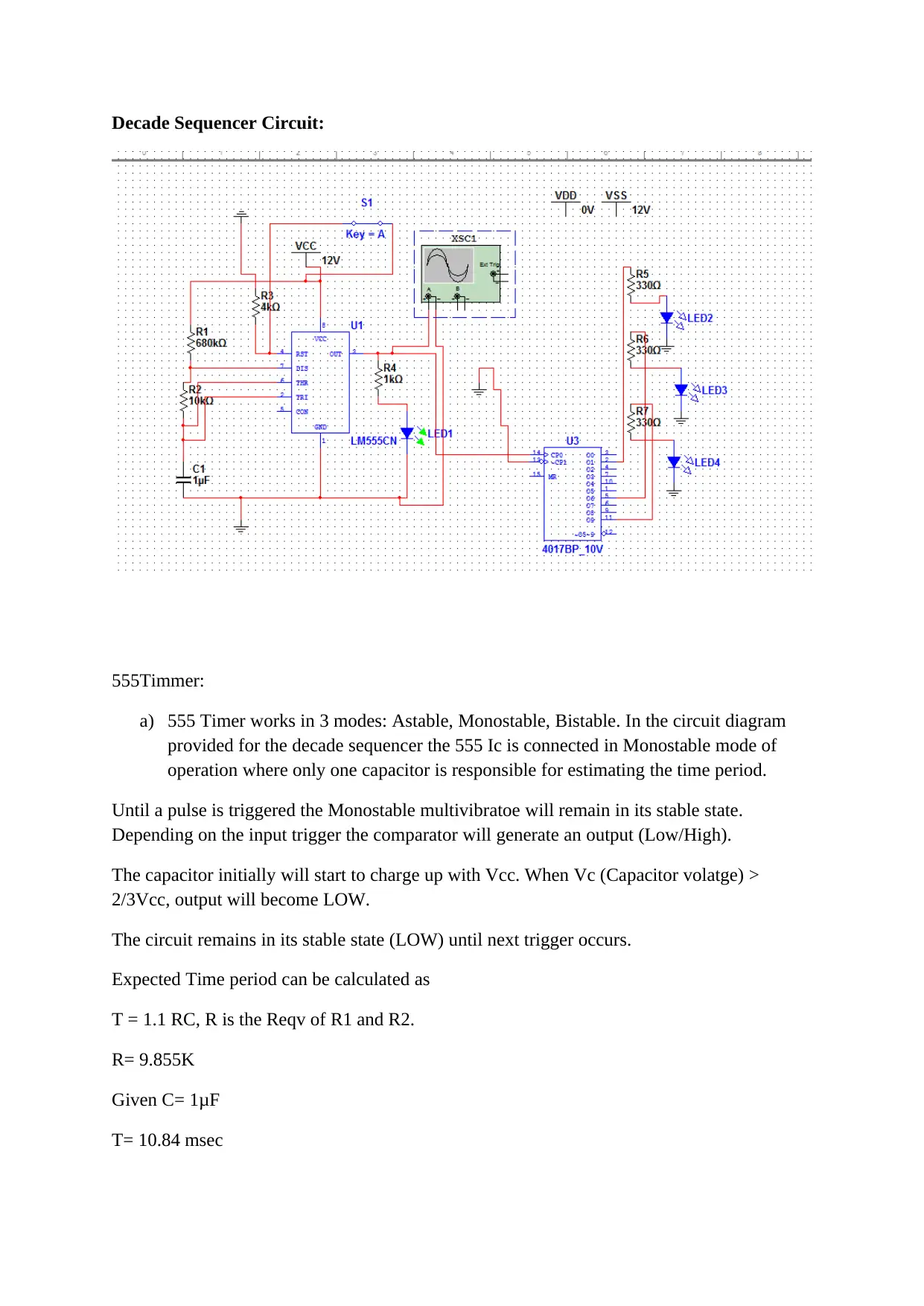
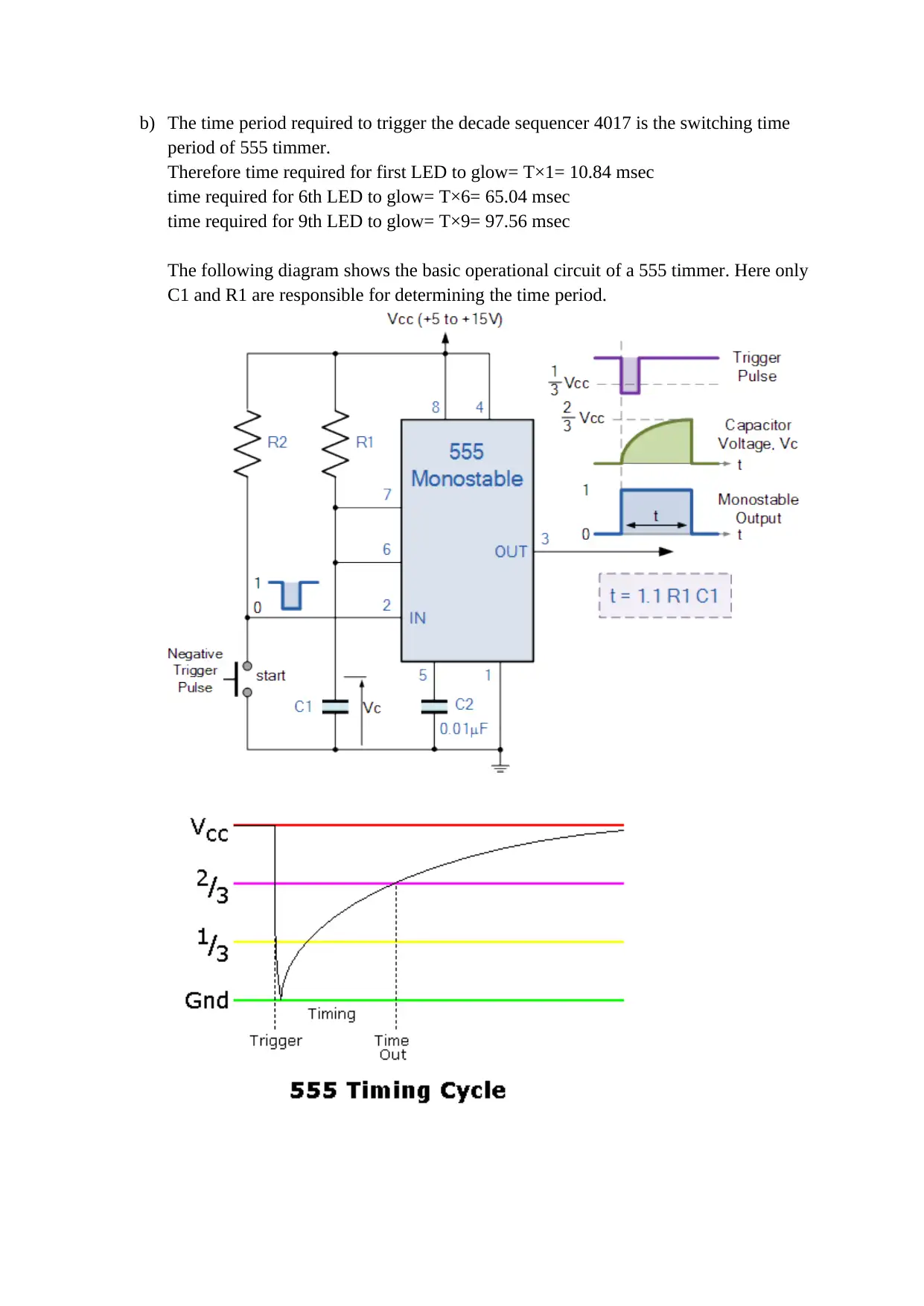
This document presents a solution for ELE1502 Electronic Circuits Assignment 2, focusing on the analysis, construction, and testing of two distinct circuits: a power supply and a decade sequencer. The power supply circuit utilizes a step-down transformer, rectifier, filter, and voltage regulators (7805 and LM317) to provide both a fixed 5V and a variable voltage output (6V-12V). The analysis includes determining the expected output voltage range of the variable regulator and verifying it through building and testing. The decade sequencer circuit employs a 555 timer in monostable mode to trigger a 4017 decade counter, creating a sequential LED display. The solution explains the operational principles of the 555 timer, calculating the time period for LED activation and referencing relevant sources for further understanding. The solution provides the expected and measured voltage ranges for the power supply, demonstrating the functionality of the circuit. Finally, the solution covers the analysis of the decade sequencer circuit and how the 555 timer is used in monostable mode to trigger the 4017 decade counter, including the calculation of timing periods for the LED sequence.
Document Page
Power Supply Circuit:
In the above circuit diagram, a step down transformer of about 20:1 turns ratio has been
taken. The AC 240 V is converted into 12 V Ac by the transformer. The step down voltage 12
V is applied to the input of the rectifier circuit, for transforming AC to DC voltage. The
capacitor 2200μF is acting as a filter, for smoothing the DC output further. Voltage regulator
IC 7805 provides a constant voltage source of 5 V and the regulator LM 317H provides the
voltage ranges from 6V-12V. The pot connected with LM 317H defines the required output
of the regulator by changing the wiper increment position. The below datasheet shows the
change in the output voltages with the increment of wiper position in 1K pot.
POT increment (%) OUTPUT voltage (Volt)
0 6
10 6.6
20 7.4
30 8.11
40 8.81
50 9.51
60 10.19
70 10.8
80 11.46
90 12.3
tabler-icon-diamond-filled.svg

Secure Best Marks with AI Grader

Need help grading? Try our AI Grader for instant feedback on your assignments.
Document Page
Decade Sequencer Circuit:
555Timmer:
a) 555 Timer works in 3 modes: Astable, Monostable, Bistable. In the circuit diagram
provided for the decade sequencer the 555 Ic is connected in Monostable mode of
operation where only one capacitor is responsible for estimating the time period.
Until a pulse is triggered the Monostable multivibratoe will remain in its stable state.
Depending on the input trigger the comparator will generate an output (Low/High).
The capacitor initially will start to charge up with Vcc. When Vc (Capacitor volatge) >
2/3Vcc, output will become LOW.
The circuit remains in its stable state (LOW) until next trigger occurs.
Expected Time period can be calculated as
T = 1.1 RC, R is the Reqv of R1 and R2.
R= 9.855K
Given C= 1μF
T= 10.84 msec
Document Page
b) The time period required to trigger the decade sequencer 4017 is the switching time
period of 555 timmer.
Therefore time required for first LED to glow= T×1= 10.84 msec
time required for 6th LED to glow= T×6= 65.04 msec
time required for 9th LED to glow= T×9= 97.56 msec
The following diagram shows the basic operational circuit of a 555 timmer. Here only
C1 and R1 are responsible for determining the time period.
Document Page
Reference:
ElectronicsTutorials (2019) Retrieved from:
https://www.electronics-tutorials.ws/waveforms/555_timer.html
Electrosome(2019) Monostable Multivibrator using 555 Timer. Retrieved from:
https://electrosome.com/monostable-multivibrator-555-timer/
CircuitToday (2018) 555 Timer as Monostable Multivibrator. Retrieved from:
http://www.circuitstoday.com/555-timer-as-monostable-multivibrator
AllAboutCircuit. (2019)Chapter 8: 555Timmer Circuit. Retrieved from:
https://www.allaboutcircuits.com/textbook/experiments/chpt-8/555-monostable-
multivibrator/
Tripode (2019) The 4017B Decade Counter. Retrieved from:
http://sensorsweep.tripod.com/sequencer.html
ElectronicsHub (2015) CD 4017 IC-Decade Counter. Retrieved from:
https://www.electronicshub.org/ic-4017-decade-counter/
ReviseOmatic V4 ( 2017) Sequential Logic Decade Counter. Retrieved from:
https://reviseomatic.org/rOmV4/rOmV4/page/45/Sequential_Logic_Decade_Counter
AllAboutCircuit (2019) Rectifier Circuit Chapter 3 - Diodes and Rectifiers. Retrieved from:
https://www.allaboutcircuits.com/textbook/semiconductors/chpt-3/rectifier-circuits/
chevron_up_icon
1 out of 4
circle_padding
hide_on_mobile
zoom_out_icon
[object Object]