Power System Protection: Fault Analysis and Current Calculations
VerifiedAdded on 2023/06/14
|9
|1442
|314
Homework Assignment
AI Summary
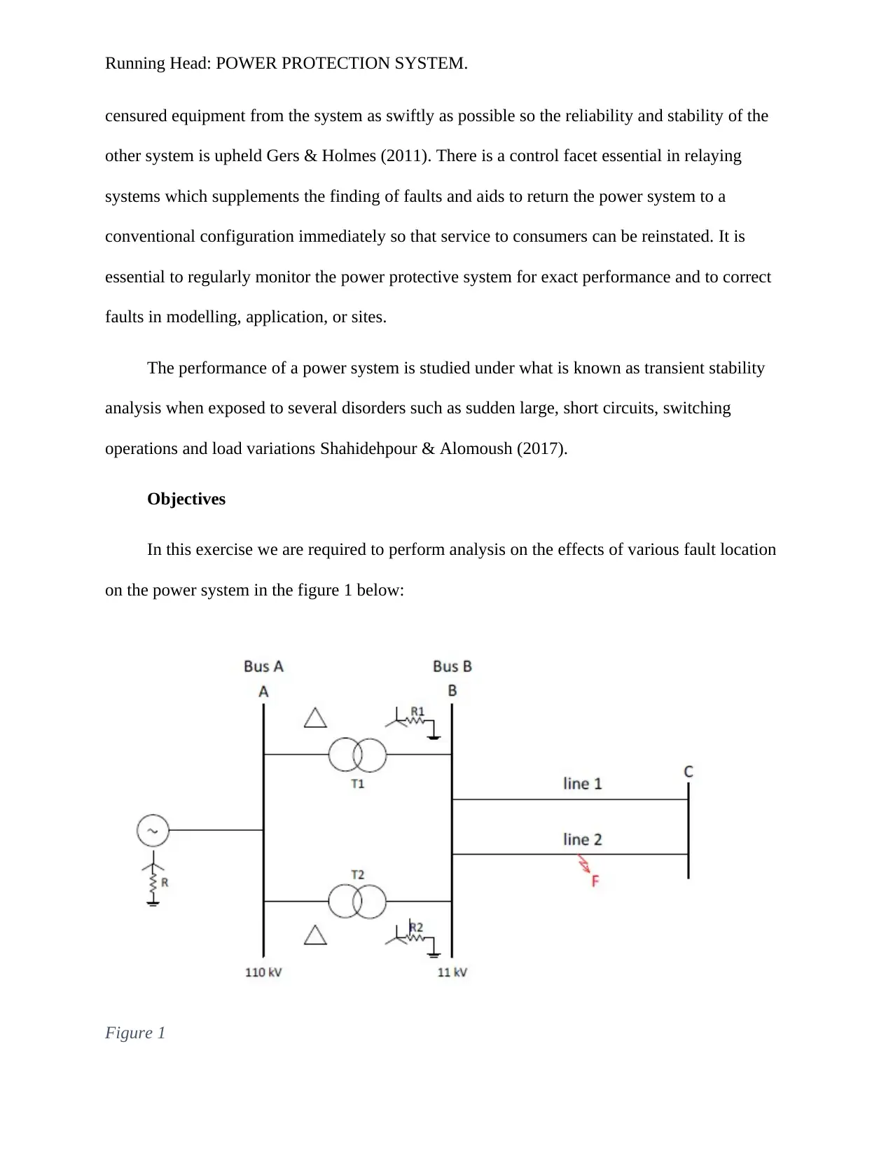
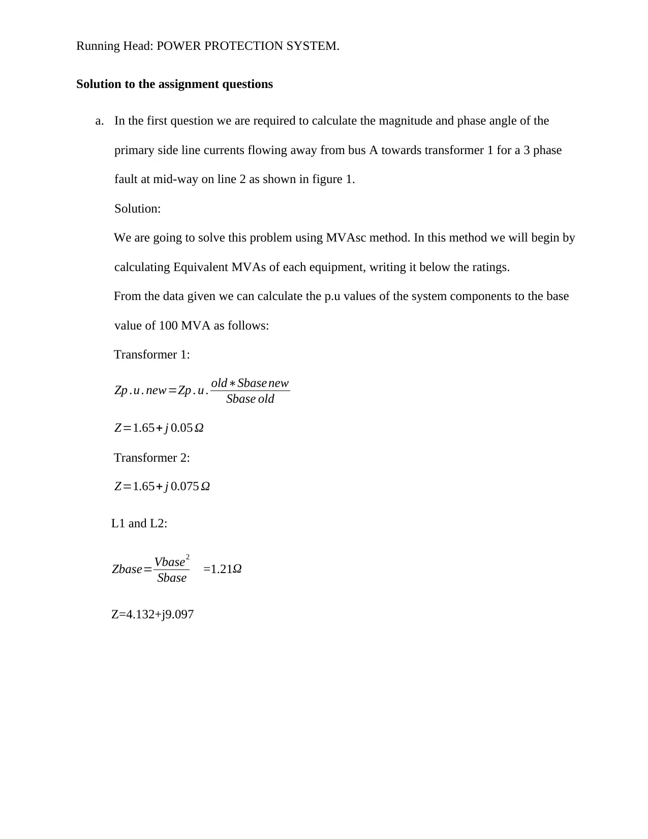
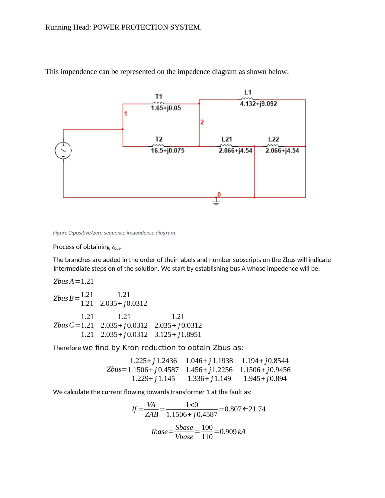
This assignment delves into power system protection, focusing on fault analysis and current calculation using the MVAsc method. It includes calculating primary side line currents for a three-phase fault, determining magnitude and phase angle for phase-to-phase faults, and analyzing phase-to-phase-to-ground faults. The solution uses impedance diagrams and Kron reduction to obtain Zbus, followed by detailed calculations of fault currents under various fault conditions. The assignment also discusses conditions under which the transformer magnetizing current cannot be assumed to be zero, emphasizing the impact of magnetic saturation and harmonic components. Desklib offers this solution and other resources for students.

Running Head: POWER PROTECTION SYSTEM.
Power Protection System
Name:
Professor:
Course:
Date:
Power Protection System
Name:
Professor:
Course:
Date:
Secure Best Marks with AI Grader
Need help grading? Try our AI Grader for instant feedback on your assignments.

Running Head: POWER PROTECTION SYSTEM.
Abstract
According to Gers & Holmes (2011), System protection is a division of electric power
engineering that deal with the principles of design and operation of equipment (protective relays)
which sense irregular power system circumstances and initiate counteractive action as swiftly as
possible in order to return the power system to its normal state. The swiftness of response is a
critical component of protective relaying scheme. In protection of power systems, reaction times
of the order of a few milliseconds are often necessary Hasse (2004). Consequently, human
involvement in the protection of a power system operation is not thinkable. The response must be
quick, automatic and ought to cause a least amount of interruption to the power system.
Introduction
According to Sallam & Malik (2011), on day-to-day basis electrical energy usage grows as a
consequence of new users being linked to the system. This consequently infers that new power
stations and transmission lines need to be constructed to cater for the high demand. Consequently,
the error level of the system is heightened by the situation. Power system scrutiny during faulted
situations offers information about relay setting, circuit breaker selection and the strength of the
system operation. Weedy (2012) argues that, during faulted circumstances, it wise to determine the
voltage and current standards in order to install protective devices to reduce the destructive effects
of such stresses on the power system. In addition to, proper management of protective relays and
the right specifications of circuit breaker rating are based on the results of the investigation.
In general, relays do not thwart destruction to equipment; they activate after some
measurable damage has already happened. Relays limit, to a degree possible, more damage to
equipment, to reduce menace to people, to lessen pressure on other equipment, and eliminate the

Running Head: POWER PROTECTION SYSTEM.
censured equipment from the system as swiftly as possible so the reliability and stability of the
other system is upheld Gers & Holmes (2011). There is a control facet essential in relaying
systems which supplements the finding of faults and aids to return the power system to a
conventional configuration immediately so that service to consumers can be reinstated. It is
essential to regularly monitor the power protective system for exact performance and to correct
faults in modelling, application, or sites.
The performance of a power system is studied under what is known as transient stability
analysis when exposed to several disorders such as sudden large, short circuits, switching
operations and load variations Shahidehpour & Alomoush (2017).
Objectives
In this exercise we are required to perform analysis on the effects of various fault location
on the power system in the figure 1 below:
Figure 1

Running Head: POWER PROTECTION SYSTEM.
Solution to the assignment questions
a. In the first question we are required to calculate the magnitude and phase angle of the
primary side line currents flowing away from bus A towards transformer 1 for a 3 phase
fault at mid-way on line 2 as shown in figure 1.
Solution:
We are going to solve this problem using MVAsc method. In this method we will begin by
calculating Equivalent MVAs of each equipment, writing it below the ratings.
From the data given we can calculate the p.u values of the system components to the base
value of 100 MVA as follows:
Transformer 1:
Zp .u . new=Zp . u . old∗Sbase new
Sbase old
Z=1.65+ j 0.05 Ω
Transformer 2:
Z=1.65+ j 0.075 Ω
L1 and L2:
Zbase=Vbase2
Sbase =1.21Ω
Z=4.132+j9.097
Secure Best Marks with AI Grader
Need help grading? Try our AI Grader for instant feedback on your assignments.

Running Head: POWER PROTECTION SYSTEM.
This impendence can be represented on the impedence diagram as shown below:
Figure 2:positive/zero sequence imdendence diagram
Process of obtaining zbus.
The branches are added in the order of their labels and number subscripts on the Zbus will indicate
intermediate steps on of the solution. We start by establishing bus A whose impedence will be:
Zbus A=1.21
Zbus B=1.21 1.21
1.21 2.035+ j0.0312
Zbus C=
1.21 1.21 1.21
1.21 2.035+ j 0.0312 2.035+ j 0.0312
1.21 2.035+ j 0.0312 3.125+ j1.8951
Therefore we find by Kron reduction to obtain Zbus as:
Zbus=
1.225+ j 1.2436 1.046+ j 1.1938 1.194+ j0.8544
1.1506+ j 0.4587 1.456+ j1.2256 1.1506+ j0.9456
1.229+ j 1.145 1.336+ j 1.149 1.945+ j 0.894
We calculate the current flowing towards transformer 1 at the fault as:
If = VA
ZAB = 1<0
1.1506+ j 0.4587 =0.807←21.74
Ibase= Sbase
Vbase = 100
110 =0.909 kA

Running Head: POWER PROTECTION SYSTEM.
Therefore If= 0.807←21.74∗0.909 kA=0.07336←21.74 kA
b. In the second part we are required to determine the magnitude and phase angle of the
primary side line currents flowing away from bus A towards transformer 2 for a phase to
phase fault at location F.
Solution:
If = Vf
Zkk 1+Zkk 2+Zf
Zf=5Ω=0.0413pu
Zkk1=Zkk2=1.046+j1.1938 pufrom Zbus
Therefore:
If = 1
1.046+ j1.1938+ 1.046+ j 1.1938+0.0413 =0.3117← 48.32 pu
Therefore If= 0.3117← 48.32∗0.909 kA=0.2833←48.32 kA
c. For phase to phase to ground fault at location F, we are required to calculate the
magnitude and phase angle of the transmission line currents flowing away from bus B in
the faulted line.
Solution:
If = Vf
ZBC 1+¿ ¿
ZBC2=ZBC1=1.945+j0.89, Vf=1<0
Zf=0
ZBC0=1.336+j1.149
Therefore: If = 1
1.945+ j0.89+ 1.945+ j0.89∗( 1.336+ j1.149 )
1.945+ j 0.89+1.336+ j1.149
=0.3219<-27.35

Running Head: POWER PROTECTION SYSTEM.
Ibase= Sbase
Vbase = 100
11 =9.091 kA
Therefore If= 0.3219←27.35∗9.091 kA=2.926←27.35 kA
d. We are required to calculate the magnitude and phase angle of the transmission lie currents
flowing away from bus B in the faulted line.
Solution:
If = Vf
ZBC 1+ZBC 0+ ZBC 2+3∗Zf
From the Zbus:
ZBC2=ZBC1=1.945+j0.89, Vf=1<0
Zf=50Ω=41.322pu
ZBC0=1.336+j1.149
If = 1
1.945+ j0.89+1.945+ j 0.89+1.336+ j 1.149+3∗41.322 =0.1669<-29.26
Therefore If= 0.1669←29.26∗9.091 kA=1.517←29.26 kA
Paraphrase This Document
Need a fresh take? Get an instant paraphrase of this document with our AI Paraphraser

Running Head: POWER PROTECTION SYSTEM.
e. In this last question we are required to discuss the conditions under which the transformer
magnetizing current can’t be assumed to be zero.
Solution:
When a transformer is connected to an ac power source even though the secondary side is
open circuited a current will flow on the primary side. This current produces flux in
ferromagnetic core. The current is composed of magnetization and core loss current. The
following justifies why we should not assume the magnetizing current to be zero.
1. The magnetization current is not sinusoidal. It has a higher-frequency component due to
magnetic saturation in the transformer core.
2. In the saturation region, a large increase in magnetizing current is required to provide a slight
increase in the flux.
3. The fundamental component of the magnetization current lags the applied voltage by 90°.
4. The higher-frequency (harmonic) component of the magnetization current increases as the
core is driven into saturation.

Running Head: POWER PROTECTION SYSTEM.
References
Gers, J. M., Holmes, E. J., & Institution of Engineering and Technology. (2011). Protection of
electricity distribution networks. London: Institution of Engineering and Technology.
Hasse, P. (2004). Overvoltage protection of low-voltage systems. London: Institution of
Electrical Engineers.
Institute of Electrical and Electronics Engineers, IEEE Industry Applications Society, IEEE
Standards Board, & American National Standards Institute. (2001). IEEE recommended
practice for protection and coordination of industrial and commercial power systems.
New York: Institute of Electrical and Electronics Engineers.
Sallam, A. A., & Malik, O. P. (2011). Electric distribution systems.
Shahidehpour, M., & Alomoush, M. (2017). Restructured electrical power systems: Operation,
trading, and volatility.
Weedy, B. M. (2012). Electric power systems. Chichester, West Sussex, UK: John Wiley &
Sons, Ltd
1 out of 9
Related Documents

Your All-in-One AI-Powered Toolkit for Academic Success.
+13062052269
info@desklib.com
Available 24*7 on WhatsApp / Email
Unlock your academic potential
© 2024 | Zucol Services PVT LTD | All rights reserved.