Power Systems Analysis Assignment: Fault Analysis and Calculations
VerifiedAdded on 2022/11/02
|17
|3206
|410
Homework Assignment
AI Summary
This assignment solution provides detailed answers to a power systems analysis homework. The solution includes multiple-choice questions and calculation problems related to per-unit impedance, transformer analysis, fault level calculations, symmetrical components, Thevenin equivalent circuits, delta-connected loads, and short circuit analysis. It covers topics such as calculating per-unit values, determining fault currents, analyzing unbalanced systems, and applying star-delta transformations. The solutions are presented with clear step-by-step calculations, formulas, and explanations, making it a valuable resource for students studying electrical engineering and power systems.

Part 1 – Multiple-Choice Questions
For the following questions, select which answer is TRUE.
Question 1 (# marks)
The per unit value of Z33kV line = (1.82 +j 2.61) Ω on a 10 MVA Base is:
a) (0.01 + j0.024) pu
b) (0.02 + j0.03) pu
c) (0.01 + j0.045) pu
d) (0.02 + j0.024) pu
Z pu= actual impedance/ base impedance
Actual impedance = 1.82 + j2.61 ohms
Base impedance = base voltage2 (kV)/ base MVA
= 332 / 10
= 108.9
Z pu= 1.82 + j2.61 / 108.9
= (0.02 + j0.024) pu
Answer d is true
Question 2 (# marks)
A 500 MVA transformer has R = 0.4% and X = 5.9%. Calculate in rectangular form the per unit
values on a 100MVA base:
a) (0.0001 + j0.012)llpu
b) (0.002 + j0.012) pu
c) (0.0008 + j0.012) pu
d) (0.001 - j0.012) pu
Zpu.new = Zpu.old* (base MVAnew )/ (base MVAold )
= (0.004 + j0.059) * 100/500
= (0.008 + j0.012) pu
Answer c is true
Question 3 (# marks)
A 132 kV bus has a balanced 3Φ system fault level of 500MVA at A, adopting a 1000MVA base
calculate the magnitude of IA 3Φ SC fault level (in kA):
a) 1.26 kA
b) 2.19 kA
Paraphrase This Document
Need a fresh take? Get an instant paraphrase of this document with our AI Paraphraser

c) 3.79 kA
d) 1.13 kA
Short circuit current, IASC = (fault MVA * 103)/√3 * base KV A
Substituting for the values in equation above
IASC = (500 * 103)/√3 * 132
= 2186 A
= 2.19 kA
Answer b is true
Question 4 (# marks)
The line voltage applied to the primary side of a 1MVA 3Φ 33/11kV transformer with a 3Φ short
circuit applied to the 11kV side equals 1625 V. The line current for this short circuit test equals 17.25
A. The impedance in per unit values ∣Z1MVA transformer∣ is:
a) 0.45 pu
b) 0.05 pu
c) 0.55 pu
d) 0.60 pu
Per unit impedance of the transformer, Z1MVA tx pu = VZ/Vn
VZ is the voltage that was applied at the LV side
Vn is rated line to line voltage of the transformer
Z1MVA txpu = 1625/33000
= 0.05p.u
Answer d is true
Question 5 (# marks)
An unbalanced 3Φ star-connected load comprises impedances ZA = 1.2/30°Ω, ZB = 1.5/20°Ω, ZC =
1.8/45°Ω. This is connected to a 3Φ supply VA= 230/0° V with a positive phase sequence. Calculate
ZTHEVENIN:
a) 2.02 /30.8 ° Ω
b) 1.01 /30.8° Ω
c) 0.98 /30.8° Ω
d) 0.49 /30.8° Ω
For the star connected loads ZA, ZB and ZC are all in parallel, thus the equivalent impedance of the
loads with the voltage sources shorted is
ZTHEVENIN = (1/1.2 < 30 + 1/1.5<20 + 1/1.8<45)-1

= 0.49<30.80
Ω
Answer d is true
Question 6 (# marks)
In Q5, calculate VON for ZN = ∞ (i.e. open circuit neutral)
a) 27.5 /85.1° V
b) 55 /85.1° V
c) 53.4 /-10.2° V
d) 106.8 /-10.2° V
ION = IA + IB + IC
= (240<0/1.2<30) + (240<240/1.5<20) + (240<120/1.8<45)
= 85.41<28.30 A
= 112.85<-410 A
VON= ION * ZTHEV
= 112.85<-41 * 0.49<30.8
= 53.4<-10.20 V
Answer c is true
Question 7 (# marks)
A two-wattmeter measurement is made of a balanced 3Φ load showing WA = 10.5 kW and WC = 15.9
kW. Calculate Q and pf:
a) Q = 17.41 kVAr, pf = 0.94
b) Q = 5.43 kVAr, pf = 0.89
c) Q = 9.35 kVAr, pf = 0.94
d) Q = 5.43 kVAr, pf = 0.94
For two wattmeter method the following formula is used to calculate the phase angle
Ø = Tan-1 ( √3∗wc−wa
wc +wa )
= Tan-1 ( √3∗15.9−10.5
15.9+10.5 )
= 19.500
Power factor = cos Ø = cos 19.5 = 0.94
Total power = 10.5 + 15.9 = 26.4 kW
From power angle, reactive power, Q = real power*tan Ø
= 26.4 * tan 19.5
= 9.35 kVAr.
Answer c is true
⊘ This is a preview!⊘
Do you want full access?
Subscribe today to unlock all pages.
Trusted by 1+ million students worldwide

Part 2 – Calculation Questions
Question 8 (4 marks)
For the following unbalanced 3Φ voltages Va= 240/15° V, Vb= 340/-65° V, Vc = 400/105°V
calculate:
(a) the positive sequence component Va1
Figure 1. balanced systems
The theory of symmetrical components solves a problem that occurs when there is unbalanced
conditions. A set on unbalanced currents or voltages can be resolved into sets of symmetrical
balanced phasors components namely: positive, negative and zero sequence. For the positive
sequence, the following formula is used to compute symmetrical components
Va1 = 1/3 (Va + a * Vb + a2 * Vc)
= 1/3 { 240<15 + (1<120 * 340<-65) + (1<240 * 400<105)}
= 282.4 < 16.3 0 V
(b) the negative sequence component Va2
For negative sequence, the following formula is used to compute symmetrical components
Va2 = 1/3 (Va + a2 * Vb + a* Vc)
= 1/3 {240<15 + (1<240 * 340<-65) + (1<120* 400<105)}
= 144.7 < -153.88 0 V
(c) the zerosequence component Va0
For zero sequence, the following formula is used to compute symmetrical components
Va0 = 1/3 (Va + Vb+ Vc)
=1/3 {240<15 + 340<-65 + 400<105}
= 102.02 <27.30 V
(d) show Va1 + Va2 +Va0 = Va
Va1 + Va2 +Va0 = 282.4 < 16.3 + 144.7 < -153.88 + 102.02 < 27.3
= 240 < 150 V
Paraphrase This Document
Need a fresh take? Get an instant paraphrase of this document with our AI Paraphraser

= Va
Question9 (20 marks)
For ZN = (2 + j0) Ω, calculate for the 2 terminals O and N:
a) Thevenin Impedance, ZTHEV
Letting Za1, Zb1 and Zc1 be equivalent impedances in phases A, B and C respectively,
Za1 = Za + ZB = 0.07<62 + 1.15<17.7 = 1.2 < 200
Zb1 = Zb + ZB = 0.07<62 + 1.542<28.64 = 1.6 < 300
Zc1 = Zc + ZC = 0.07<62 + 1.9353<39.23 = 2.0 < 400
To determine Thevenin impedance voltage sources are shorted and the load is open circuited, and it’s
the impedance of the circuit seen from terminals O and N. since they share the same terminal,
impedances, Za1, Zb1 and Zc1 are all in parallel.
Thevenin impedance, ZTHEV = {1/1.2<20 + 1/1.6<30 + 1/2.0<40}-1
= 0.52<28.30 Ω
b) Norton current, ION NOR
Norton current ION NOR= IA + IB + IC
= (240<0/1.2<20) + (240<120/1.6<30) + (240<240/2.0<40)
= 85.41<28.30 A
c) Thevenin Voltage, VTHEV
VTHEV = ION NOR * ZTHEV = 85.41<28.3 * 0.52<28.3
= 44.41<56.60 V
d) Sketch the Thevenin Equivalent Circuit showing the terminals O and N, also VTHEV,
ZTHEV and their values including the load impedance ZN

a) For ZN = (2.0 + j0) Ω (i.e. a hot joint in the neutral), calculate:
i. IN
IN = VTHEV / (ZTHEV + ZN )
= 44.41<56.6 / (2<0 + 0.52<28.3)
= 17.978<50.870 A
ii. VON
VON = IN * ZN
= 17.978<50.87 * 2<0
= 35.956<50.87 V
iii. IA
IA = Va/ (ZA + Za)
= (240<0/1.2<20)
= 200<-200A
iv. IB
IB= Vb/ (ZB + Zb)
= (240<120/1.6<30)
= 150 < 93.870 A
v. VA
VA = Va - IA * Za
= 240 <0 – (200<-200 * 0.07<62)
= 230<-2.34 V
⊘ This is a preview!⊘
Do you want full access?
Subscribe today to unlock all pages.
Trusted by 1+ million students worldwide

vi. VB
VB = Vb– IB* Zb
= 240 <120 – (150 < 93.87 * 0.07<62)
= 231<118.5 V
vii. VAB
VAB = VA – VB
= 230<-2.34 - 231<118.5
= 400<32 V
Question 10 (20 marks)
Data: ZAB = ZBC = ZCA = 15/30°; Za = Zb = Zc = 0.3/45°
a) Calculate Z equivalent 𝖸-connected value for 𝜟 = ZA = ZB = ZC
ZA = (ZAB * ZCA)/(ZAB + ZBC + ZCA)
= (15<30 2) / (3* 15<30)
= 5 < 30 Ω
Since it’s a balanced load,
ZA = ZB = ZC = 5 < 30 Ω
b) Sketch the 1Ø equivalent circuit showing VA, Za, ZA, IA
Paraphrase This Document
Need a fresh take? Get an instant paraphrase of this document with our AI Paraphraser

Calculate:
c) IA
IA = VA / (Za + ZA)
= 230 < 0 / (0.3<45 + 5<30)
= 43.475< -30.84o A
d) Voltage at point A of delta
VA∆ = VA – IA * ZA
= 230<0 – (43.475<-30.84 * 0.3<45)
= 217<-0.8o V
e) IB
IB = VB / (Zb + ZB)
= 230 <240 / (0.3<45 + 5<30)
= 43.475< -150o A
f) Voltage at point B of delta
VB∆ = VB – IB * Zb
= 230<240 – (43.475<-150 * 0.3<45)
= 217<-120.89o V
g) VAB (i.e. betweenpoints A and B of delta)
From part d and f the voltage between points A and B of the delta configuration is calculated as

VAB = VA – VB
= 217<-0.8 – 217<-120.89
= 375.85 < 29.2 V
h) S total 3Φ ∆ connected load in polar and rectangular form. Write the units under each quantity and write
the symbols under these.
S total 3Φ ∆ connected load= 3(VØ * I*Ø)
= 3(217<-0.8o* 43.475 < 30.84o)
= 28.30223<300 kVA (polar form)
= (24.500 + j14.168) kVA
i) Load pf
From part h, Ø = 30 degrees
Load power factor = cos Ø
= cos 30
= 0.866
= 0.9
Question 11 (20 marks)
a) Calculate in per unit
i. X1 C to bus
XCpu= Base MVA / fault MVA
= 10 MVA /250 MVA
= 0.04 pu
ii. X1 11kV line
Xlinepu = Z ( ohms )∗base kVA /V 2
⊘ This is a preview!⊘
Do you want full access?
Subscribe today to unlock all pages.
Trusted by 1+ million students worldwide
= 1.55 * 10*106 /110002
= 0.128 pu
iii. X1 T
X1T pu.new= Zpu old * (kV2baseold* MVAbasenew)/ (kV2basenew* MVAbaseold)
= 0.05 * 10/1 * 4152/4152
=0.5pu
iv. X1 415V line
X415linepu = Z ( ohms )∗base kVA/V 2
= 0.035 * (10*106 /4152)
= 2.03pu
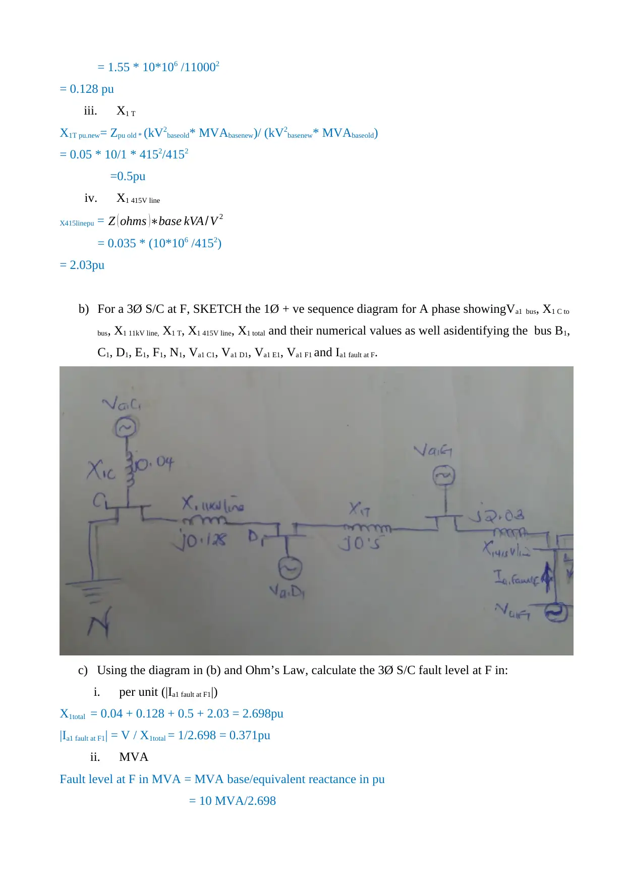
b) For a 3Ø S/C at F, SKETCH the 1Ø + ve sequence diagram for A phase showingVa1 bus, X1 C to
bus, X1 11kV line, X1 T, X1 415V line, X1 total and their numerical values as well asidentifying the bus B1,
C1, D1, E1, F1, N1, Va1 C1, Va1 D1, Va1 E1, Va1 F1 and Ia1 fault at F.
c) Using the diagram in (b) and Ohm’s Law, calculate the 3Ø S/C fault level at F in:
i. per unit (|Ia1 fault at F1|)
X1total = 0.04 + 0.128 + 0.5 + 2.03 = 2.698pu
|Ia1 fault at F1| = V / X1total = 1/2.698 = 0.371pu
ii. MVA
Fault level at F in MVA = MVA base/equivalent reactance in pu
= 10 MVA/2.698
= 0.128 pu
iii. X1 T
X1T pu.new= Zpu old * (kV2baseold* MVAbasenew)/ (kV2basenew* MVAbaseold)
= 0.05 * 10/1 * 4152/4152
=0.5pu
iv. X1 415V line
X415linepu = Z ( ohms )∗base kVA/V 2
= 0.035 * (10*106 /4152)
= 2.03pu
b) For a 3Ø S/C at F, SKETCH the 1Ø + ve sequence diagram for A phase showingVa1 bus, X1 C to
bus, X1 11kV line, X1 T, X1 415V line, X1 total and their numerical values as well asidentifying the bus B1,
C1, D1, E1, F1, N1, Va1 C1, Va1 D1, Va1 E1, Va1 F1 and Ia1 fault at F.
c) Using the diagram in (b) and Ohm’s Law, calculate the 3Ø S/C fault level at F in:
i. per unit (|Ia1 fault at F1|)
X1total = 0.04 + 0.128 + 0.5 + 2.03 = 2.698pu
|Ia1 fault at F1| = V / X1total = 1/2.698 = 0.371pu
ii. MVA
Fault level at F in MVA = MVA base/equivalent reactance in pu
= 10 MVA/2.698
Paraphrase This Document
Need a fresh take? Get an instant paraphrase of this document with our AI Paraphraser
= 3.706 MVA
iii. kA
ISC = MVA fault/ (√ 3∗nominal voltage( kV ))
= 3.706/( √3∗0.415 kV )
= 5.156 kA
d) Calculate in per unit during a 3Ø S/C at F:
i. |Va1 C1|
Fault level at C in MVA = MVA base/equivalent reactance in pu
= 10/0.04
= 250
Voltage at bus 1, Va1 C1 = MVA fault/√ 3 * Isc
= 250* /√3 * 5.156
= 28 Kv
Per unit voltage=actual voltage/base voltage
=28/11 kV
=2.545p.u
ii. |Va1 D1|
Fault level at D in MVA = MVA base/equivalent reactance in pu
= 10/0.04 + 0.128
= 60
Voltage at bus 1, Va1 D1 = MVA fault/√ 3 * Isc
= 60* /√3 * 5.156
= 6.7 kV
Per unit voltage=actual voltage/base voltage
=6.7/11 kV
=0.61p.u
iii. |Va1 E1|
Fault level at E in MVA = MVA base/ equivalent reactance in pu
= 10/0.04 + 0.128 + 0.5
= 15
Voltage at bus 1, Va1 E1 = MVA fault/√ 3 * Isc
= 15* /√3 * 5.156
= 1.68 kV
Per unit voltage=actual voltage/base voltage
=1.68/0.415 kV
=4.048p.u
iv. |Va1 F1|
Fault level at F in MVA = MVA base/ equivalent reactance in pu
= 10/0.04 + 0.128 + 0.5 + 2.03
= 3.7
Voltage at bus 1, Va1 F1 = MVA fault/ √ 3 * Isc
= 3.7 * /√3 * 5.156
= 0.414 kV
Per unit voltage=actual voltage/base voltage
=0.414/0.415 kV
=0.9976p.u
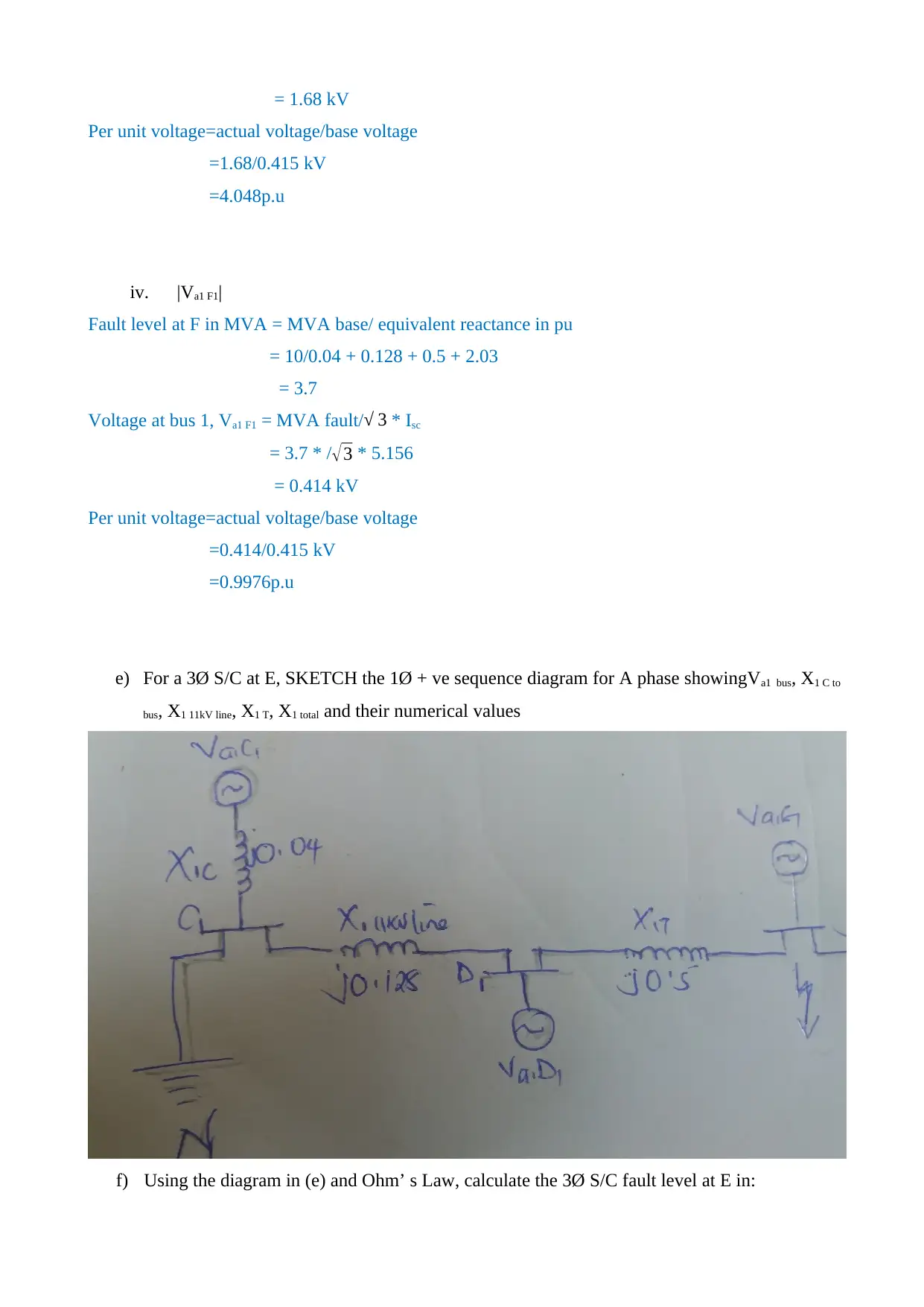
e) For a 3Ø S/C at E, SKETCH the 1Ø + ve sequence diagram for A phase showingVa1 bus, X1 C to
bus, X1 11kV line, X1 T, X1 total and their numerical values
f) Using the diagram in (e) and Ohm’ s Law, calculate the 3Ø S/C fault level at E in:
Per unit voltage=actual voltage/base voltage
=1.68/0.415 kV
=4.048p.u
iv. |Va1 F1|
Fault level at F in MVA = MVA base/ equivalent reactance in pu
= 10/0.04 + 0.128 + 0.5 + 2.03
= 3.7
Voltage at bus 1, Va1 F1 = MVA fault/ √ 3 * Isc
= 3.7 * /√3 * 5.156
= 0.414 kV
Per unit voltage=actual voltage/base voltage
=0.414/0.415 kV
=0.9976p.u
e) For a 3Ø S/C at E, SKETCH the 1Ø + ve sequence diagram for A phase showingVa1 bus, X1 C to
bus, X1 11kV line, X1 T, X1 total and their numerical values
f) Using the diagram in (e) and Ohm’ s Law, calculate the 3Ø S/C fault level at E in:
⊘ This is a preview!⊘
Do you want full access?
Subscribe today to unlock all pages.
Trusted by 1+ million students worldwide
1 out of 17

Your All-in-One AI-Powered Toolkit for Academic Success.
+13062052269
info@desklib.com
Available 24*7 on WhatsApp / Email
![[object Object]](/_next/static/media/star-bottom.7253800d.svg)
Unlock your academic potential
Copyright © 2020–2026 A2Z Services. All Rights Reserved. Developed and managed by ZUCOL.