Differential Protection of Power Transformers Using Current & Voltage
VerifiedAdded on 2020/07/22
|16
|4808
|336
Report
AI Summary
This report delves into the critical topic of power transformer protection within electrical engineering, focusing on the challenges and solutions associated with maintaining grid reliability. The core of the report revolves around an improved differential-relay algorithm that utilizes current and voltage ratios to swiftly isolate transformers during fault conditions, preventing damage and blackouts while minimizing mal-operations. The research investigates various scenarios, including inrush currents, internal faults, and simultaneous inrush and fault conditions, highlighting the effectiveness of the ratio-based scheme in enhancing accuracy, reliability, and security. The literature review encompasses various protection schemes, emphasizing the importance of differential protection. The methodology includes a detailed analysis of existing protection methods, and the report also discusses the tools, techniques, and experimental setups used to validate the proposed algorithm. Ultimately, the report aims to provide a comprehensive understanding of power transformer differential protection, offering valuable insights for electrical engineers and researchers involved in power system design and operation.
Power Transformer
Differential Protection Using
Current and Voltage ratios.
Differential Protection Using
Current and Voltage ratios.
Paraphrase This Document
Need a fresh take? Get an instant paraphrase of this document with our AI Paraphraser
EXECUTIVE SUMMARY
In Electrical Engineering, power system is the greatest topic. There are various devices,
machines, tools and instruments used are mentioned. Further, about their protection and effective
working. The current report is about the challenges that are faced by transformer in its
protection. For this, accelerated and efficient differential-relay algorithm which at the time of
fault separates the transformer from the online grid that prevents it from getting damage or
blackout. There should not be any mal-operation performed at the time of algorithm. Moreover,
while distinguishing among the operating situation that is between the magnetizing inrush
current and fault conditions. Present report highlights the protection of Power transformers in
grid through improved differential protection scheme. It is ratio based scheme and is related to
absolute difference and sum of the current ratio in all phases. Along with this, it is supplemented
with the help of ratio of the absolute variation and summation of both the terminal voltage
winding that is V1 and V2 across attached phase. The algorithm will generate the gaps that will
assist in preventing the mal-operation that generally occurs at the time of faulty conditions in 3-
phase X-mer differential protection scheme due to transient and magnetic-inrush flow of current.
Additionally, there is coinciding inrush current along with internal-fault, and faults with CT
saturation. Finding or information gathering of this project is by using both V/I ratios mentions
that there will be higher accuracy, more reliability, security as-well-as it will be dependable
relay. The research comprise of various conditions that occur in the power transformers such as
inrush-conditions, internal-fault and its simultaneous-inrush. If used for the power transformer, it
will be more accurate, dependable, faster and secure relay.
There are various application of activated carbon adsorption where large amounts of
activated-carbons are used for purification of domestic-and-industrial waste-water. However,
there are certain changes in organic abortion as carbon only attracts to non-organic. The organic
compounds are polar or non-polar and depends only on electrostatic interactions. So these
activated carbon adsorption can be helpful in removing the domestic-and-industrial waste water
(Organic and inorganic)
These waste can be removed by using the activated-carbons adsorption by using methods
such as Adsorption isotherms, Column adsorption, Effluent concentration. These are effective
methods to remove waste from water.
INTRODUCTION
Industrialization and increasing needs of humans have changed the way people use
technological devices. However, in order to run any device or machine there is need of electrical
power that too consistent and reliable. For the reliable supply there is need of effective and
SMART grid system with all the devices and machine working at the time of failure. In electrical
grid system there are two main machines that are too expensive and are necessary to be
protected. These are generator/alternator and Transformer (Ali and et. al., 2016). As alternator is
on the generating side so if there is any power failure the system is de-attached from main line
but in case of transformer this can not be performed. Due to this purpose there are various types
of protection devices are connected so that it can be protected. For electrical system, transformer
are used for transforming voltage from one part to another using mutual induction process. There
are two main use of it, either it is used as step-up at the time of transferring from grid to
substation, in industrial or heavy use areas. The other is step-down which is used at distribution
network and at homes for smaller application. At grid side there is use of power transformer as
they have higher rating of voltage and current. The machine needs to be protected from two
faults that are internal and external.
For the reliable operation, there is need of operation and maintenance so that protection
from the faults can be made. Additionally, the devices are used at higher voltage, temperature
which makes it expose to high inrush currents and external faults. In order to protect there are
various protective devices used such as relays, oils and monitor system which are placed based
on rating of transformer. There are various parameters that are overlooked if the faults occur.
These are urgency of load, size of system on the basis of the total load. Power transformers
having higher rating, the protection used is percentage differential. It is completely related to the
current flowing in the primary and secondary components of machine. All the machines are
made to work at the rated limit however, if the current and voltage value has increased then there
is need of protection. Protective relays are to protect the machine from magnetic-inrush-current,
external-faults with CT saturation (Current transformer), simultaneous-inrush with internal-faults
(Murugan and et. al., 2017). In transformer, major faults occur due to Inrush current due to
which there can be arcing, noise or wires may even burn. Along with this, at starting of
transformer there is high inrush current. Here, differential protection scheme detecting faults is
evaluated. It provides protection based on 3-general methods: overtime current, percentage
⊘ This is a preview!⊘
Do you want full access?
Subscribe today to unlock all pages.
Trusted by 1+ million students worldwide
differential relays that is flow of current in protection zone and percentage differential relays
with restraint by harmonics method (Mostafaei and Haghjoo, 2016, Sendilkumar, Mathur and
Henry, 2010).
The undergoing is to seeks about the identifying the different protection scheme that are
used to protect power transformer. The report will especially aim at undertaking protection
system using the Differential Protection Using Current and Voltage ratios that will be beneficial
for grid system and is highly reliable at the time of power failure. The study will can be used
across the globe at any power transformer. A literature review is written which will further
elaborate the topic. After the literature section, the study focus on various tools and techniques
used to complete the methodology,
experimental setup for determining the other areas and after that outcome and relevance are
mentioned. Without the use of project plan, research can never be completed, so for the complete
project planning Gantt Chart was made.
LITERATURE REVIEW
In power protection, grid protection is very important duty to maintained by the electrical
engineers. It is required so that continuity and reliability can be maintained even at the time of
blackout, peak loads and surges. Devices such as alternator and transformer that have higher
rating are high current and voltage ratios needs greater protection. At the time of issues alternator
can be separated from main grid system, however, this cannot be performed with transformer so
there is great need of its protection (Bejmert, Rebizant and Schiel, 2014, Rahmati and Sanaye-
Pasand, 2015). Ali and et. al. (2016) have noted that using the differential protection transformer
where they mentioned about the three ways through which internal-fault can be evaluated. They
mentioned that at the time of loaded energization, current and voltage ratio will be greater than 0
and will be less than 1 and is completely depended on ratio of I1 and I2. However, through this
only internal faults can be can be reversed there will be no impact on the external faults. Its
condition will mostly depend on the Differential protection algorithm, it also helps in getting
robust, secure and dependable relay for power transformers. Murugan and et. al. (2017) who
undertook Empirical Fourier Transform-Based Power Transformer Differential Protection
However, there are various methods mentioned but Sendilkumar, Mathur and Henry (2010) have
carried out their study using the using HS-transform and support vector machine. In this study,
they have highlighted the ways like energy and standard deviation which were evaluated using
Paraphrase This Document
Need a fresh take? Get an instant paraphrase of this document with our AI Paraphraser
the samples of differential current and parseval’s theorem. They act as the faults inputs of SVM.
Through this, finding were made on the inrush and fault current. For this purpose also they have
used MATLAB AND SIMULINK software. The results they gained were really impressive as
overall accuracy was found to be around 92.85%.
Bejmert, Rebizant and Schiel (2014) have performed the similar study with the help of
fuzzy logic based inrush stabilization. For carrying out the project they used the secondary
harmonic restraint that are used to differentiate among the fault and X-mer inrush conditions.
However, many researchers have identified that there were some limitation in this research.
Though, they made the finding which relates to the fuzzy reasoning techniques. The outcomes
they achieved were about the reliable and much more sensitive which cannot be shown through
the normal or traditional methods. Another researchers, Rahmati and Sanaye-Pasand (2015) have
made research using multi criteria decision-making. They have carried out their report using the
overall protection scheme for power transformers. With the help of the differential and
transformer relays they identified the protection but the relay that was used was multi-criteria
based. In their research, they have tried to evaluate the issues raised by considering that the
operation performed by the relay is independent (Liu and Dinavahi, 2016, Marks and et. al.,
2016, Mirsalim and Masoum, 2017). There was no reliability and continuation in the supply
system when multiple relays were operated.
In year 2014, Madhan kumar, Murugan and Chandramoghan have conducted research on
the models using the PSCAD Simulation software. They mentioned that faults that occur inside
the transformer should not affect the faults that are outside the zone of protection. In simple
words if fault occur the external system of the transformer will not operate. However, due they
have not conducted the research on the actual transformer so reliability and consistency of the
report cannot be maintained (Simon and et. al., 2016, Patel, Mistry and Chothani, 2016, Abbas,
and et. al., 2016).
In grid the supply is 3-phase so internal and external faults must be evaluated using this
supply system. Moreover, the supply is provided using the star-delta transformer so study must
be made in these areas. Chaudhari, Shah and Siddiqui (2015) have conducted research on the
internal and external faults using the PSCAD Simulation software. They have conducted the
study on the Star-delta transformation that is mostly used at the grid station at the time of supply
system. They have carried out the research on the internal-faults. At this position, magnetizing
inrush current due to energization of the X-former must not perform its work on no load
conditions. For the evaluation process they have carried out the Fast Fourier Transform
technique to understand the differential protective scheme and operating characteristics (Anishek
and et. al., 2016, Ashraf and et. al., 2017, Babu and Gargava 2017). They have highlighted the
fault discrimination can be measured using the FFT harmonics components. The study
highlighted some
of the advancement required but there is more improvement is required as there is nothing about
the external faults and about the fault and inrush current. Also, most of the researcher have not
carried out the research on the current direction criterion that is utilized to discriminate between
loaded energization. All the gaps that existed in the previous studies are calculated through this
study. Some of the authors have suggested that there is greater reliability if MATLAB simulation
network was used instead of PSCAD Simulation software (Cui and et. al., 2016,El Arroudi and
Joos, 2017, Hashemnia Abu-Siada and Islam, 2016, Hernandez and Labib, 2017, Jarman and et.
al., 2017). Further, using the research the major non-operational part that is protective relays can
be highlighted.
Important literature review papers that were used at the time of preparation of study
proposal are Ali and et. al. (2016) that presented the use of differential protection algorithm.
Murugan and et. al. (2017) who undertook Empirical Fourier Transform-Based Power
Transformer Differential Protection and Sendilkumar, Mathur and Henry (2010) where they
made finding related to same protection using wavelet transform and PNN.
RESEARCH QUESTION, AIM/OBJECTIVES
From the above section the research gap can be carried out that is related to the protection
of Power transformer using differential protection using current and voltage ratios. There is great
importance of this study as transformer are expensive machines and its protection will increase
its reliability and efficiency at time of working. For the following research, these are question
that were needed to be identified in this study:
How differential protection algorithm is based on I/V ratios?
What are the ways by which fault and inrush current can be distinguished at no-load
energization?
What is used at the time of internal-fault to detect transformer energization?
Which criteria is used to differentiate between internal and external faults?
⊘ This is a preview!⊘
Do you want full access?
Subscribe today to unlock all pages.
Trusted by 1+ million students worldwide
The aim of the study is to determine how Power Transformer Differential Protection can
be done using Current and Voltage ratios. It is one of the key areas of power system protection
and is based Grid system. The objectives of the project are as
follows;
To determine differential protection algorithm and its relation with I/V ratios.
To develop methods that shows current ratio can be used to distinguish among the fault
and inrush current at no-load energization.
To show how voltage ratio is used to detect transformer energization on internal fault.
To identify the ways by which current direction criterion can be used to discriminate
between external-and-internal-faults
THEORETICAL CONTENT/METHODOLOGY
The methodology will utilize the MATLAB simulation networks to evaluate the Power
Transformer Differential Protection Using Current and Voltage ratios. For this a model was
made using the MATLAB multi-winding transformer. Down below is the methodology proposed
for the this methods is shown:
Starting from the percentages differential protection. Basic principle on which it is based
is that the value of restraint current is more than the differential current. With the help of one
cycle Discrete Fourier Transform (DFT) the magnitude of primary and secondary currents/phase
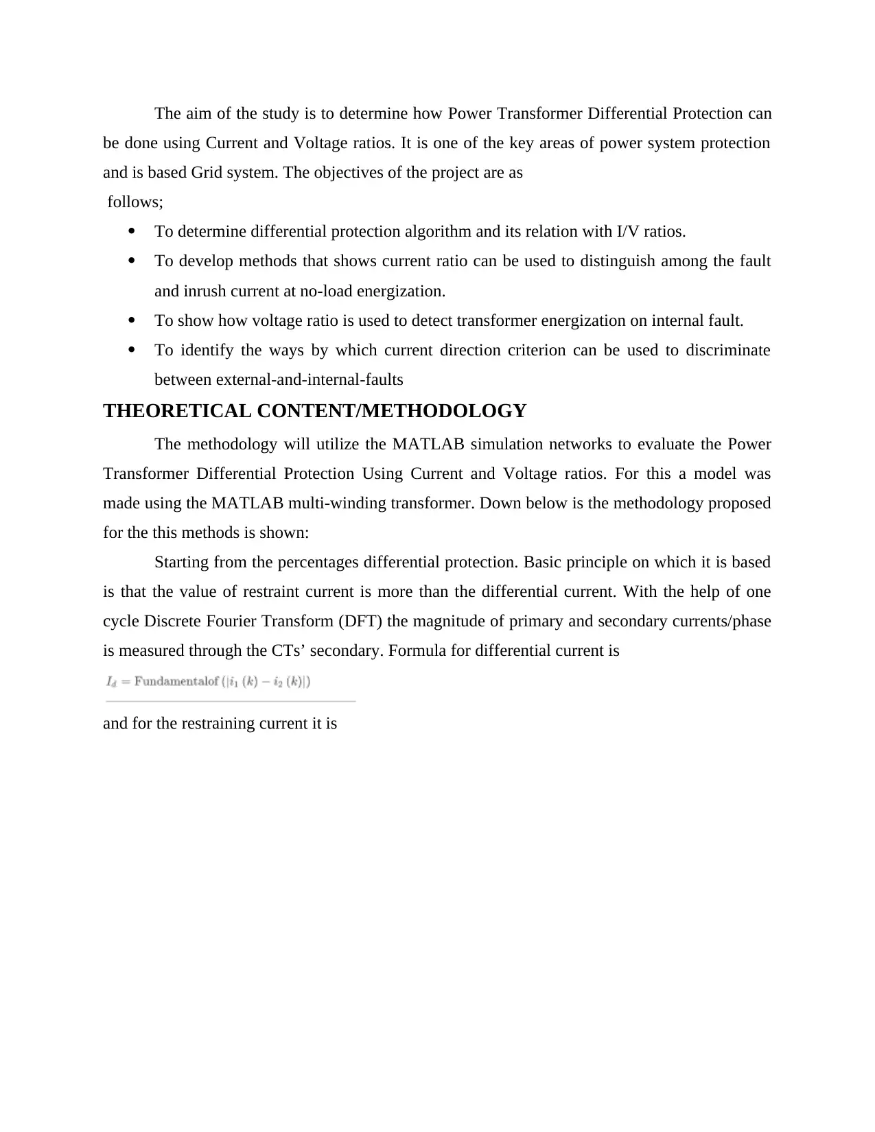
is measured through the CTs’ secondary. Formula for differential current is
and for the restraining current it is
be done using Current and Voltage ratios. It is one of the key areas of power system protection
and is based Grid system. The objectives of the project are as
follows;
To determine differential protection algorithm and its relation with I/V ratios.
To develop methods that shows current ratio can be used to distinguish among the fault
and inrush current at no-load energization.
To show how voltage ratio is used to detect transformer energization on internal fault.
To identify the ways by which current direction criterion can be used to discriminate
between external-and-internal-faults
THEORETICAL CONTENT/METHODOLOGY
The methodology will utilize the MATLAB simulation networks to evaluate the Power
Transformer Differential Protection Using Current and Voltage ratios. For this a model was
made using the MATLAB multi-winding transformer. Down below is the methodology proposed
for the this methods is shown:
Starting from the percentages differential protection. Basic principle on which it is based
is that the value of restraint current is more than the differential current. With the help of one
cycle Discrete Fourier Transform (DFT) the magnitude of primary and secondary currents/phase
is measured through the CTs’ secondary. Formula for differential current is
and for the restraining current it is
Paraphrase This Document
Need a fresh take? Get an instant paraphrase of this document with our AI Paraphraser
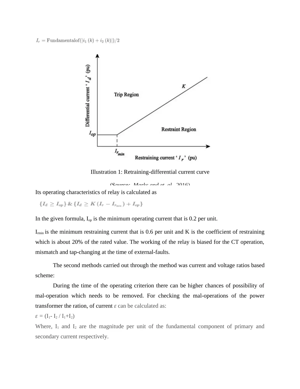
Illustration 1: Retraining-differential current curve
(Source: Marks and et. al., 2016)
Its operating characteristics of relay is calculated as
In the given formula, Iop is the minimum operating current that is 0.2 per unit.
Irmin is the minimum restraining current that is 0.6 per unit and K is the coefficient of restraining
which is about 20% of the rated value. The working of the relay is biased for the CT operation,
mismatch and tap-changing at the time of external-faults.
The second methods carried out through the method was current and voltage ratios based
scheme:
During the time of the operating criterion there can be higher chances of possibility of
mal-operation which needs to be removed. For checking the mal-operations of the power
transformer the ration, of current ε can be calculated as:
ε = (I1- I2 / I1+I2)
Where, I1 and I2 are the magnitude per unit of the fundamental component of primary and
secondary current respectively.
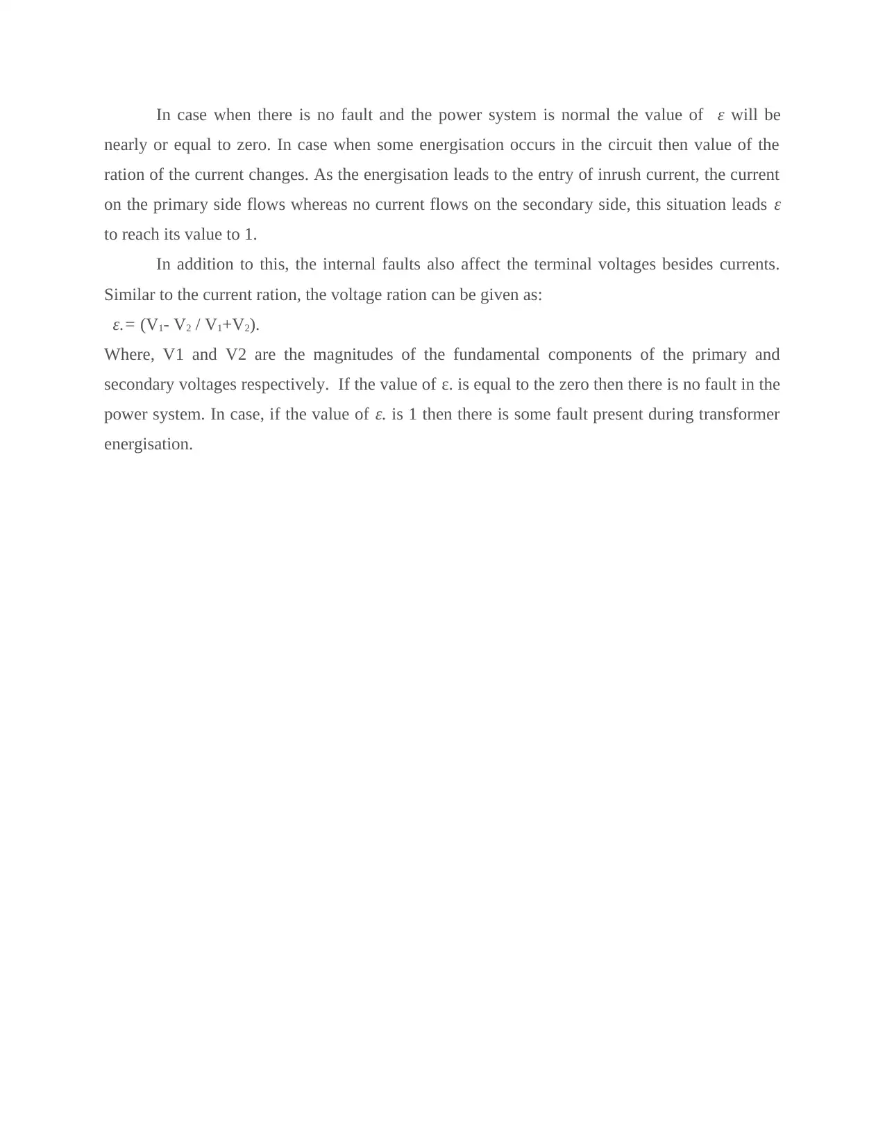
In case when there is no fault and the power system is normal the value of ε will be
nearly or equal to zero. In case when some energisation occurs in the circuit then value of the
ration of the current changes. As the energisation leads to the entry of inrush current, the current
on the primary side flows whereas no current flows on the secondary side, this situation leads ε
to reach its value to 1.
In addition to this, the internal faults also affect the terminal voltages besides currents.
Similar to the current ration, the voltage ration can be given as:
ε.= (V1- V2 / V1+V2).
Where, V1 and V2 are the magnitudes of the fundamental components of the primary and
secondary voltages respectively. If the value of ε. is equal to the zero then there is no fault in the
power system. In case, if the value of ε. is 1 then there is some fault present during transformer
energisation.
⊘ This is a preview!⊘
Do you want full access?
Subscribe today to unlock all pages.
Trusted by 1+ million students worldwide
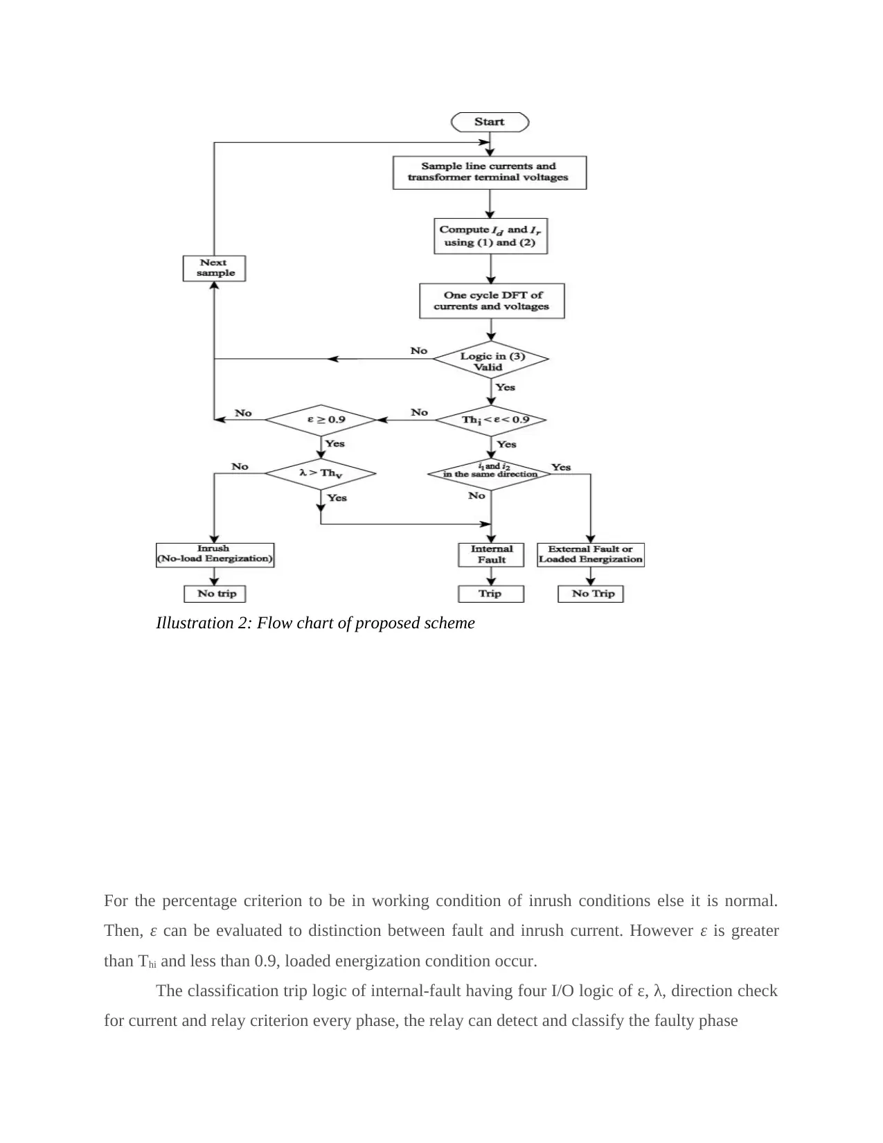
Illustration 2: Flow chart of proposed scheme
For the percentage criterion to be in working condition of inrush conditions else it is normal.
Then, ε can be evaluated to distinction between fault and inrush current. However ε is greater
than Thi and less than 0.9, loaded energization condition occur.
The classification trip logic of internal-fault having four I/O logic of ε, λ, direction check
for current and relay criterion every phase, the relay can detect and classify the faulty phase
Paraphrase This Document
Need a fresh take? Get an instant paraphrase of this document with our AI Paraphraser
It is created using the MATLAB software. Sampling frequency is 2KHz. The value of
current is 1200/5 and 100/5 for the LV and HV sides. Moreover, magnetizing characteristics are
shown for the CTs’ saturation
EXPERIMENTAL SET-UP
For carrying out the proposed study there will be need of data acquisition so that for the
provided methodology, evaluation outline can be completed. The data availability for the
evaluation would require the permission and collaboration as without them the study cannot be
conducted. The key authorities that were identified for completing these research are the
educational department, Department of Electrical Engineering. There is limitations for
completing the project as permission from the Grid supervisor and electricity distributor in the
ACT is ActewAGL in particular.
Other than this, the software that was used for completing the report that is helpful in
identifying and mentioning about the graphs is MATLAB. It is widely used by the electrical
engineers to enhance and accelerate the process. It is highly used to solve the graphical values
and for the graphical multi-domain simulation and for the dynamic and embedded system.
Columbia University in the City if New York has highlighted the use of MATLAB for the
electrical engineers. Moreover, they have mentioned about the simulation process that are highly
used by engineers in practical world.
RESULTS, OUTCOME AND RELEVANCE
The carried out research is about the transformer differential protection techniques that is
related to current and voltage ratio. The method was evaluated in the line components and
terminals voltages that provide supply to the power transformer. Optimal outcomes obtained are
inrush and fault conditions can only be discriminated by current ration while transformer
energization on internal fault can only be evaluated using the external-faults. At the time of
external faults and loaded energization, there is rise of current restrain for which there is use
current direction criterion. Due to lack of time following scenarios of fault and non-fault
conditions are mentioned in the report, these are no-load energization, simultaneous-loaded
energization with internal-fault, external-fault with CT saturation. From the study it can be
demonstrated that algorithm shown the difference between magnetizing-inrush current and
faulty-conditions in almost 1-1/2 power frequency cycle. Moreover, it was found that the
existence faulty-resistance and CT-saturation are different when various situations are taken.
Outcomes that are carried out using proposed technique can be used to identify and sort
out faulty cases from 3% of transformer windings. Besides this, it can be carried by taking the
neutral point in the short time that is at the time of fault. From the techniques, following possible
outcomes can be mentioned, these are, unsophisticated, reliable, assured and time-tested in
appreciating the inrush-currents from the fault-currents. However, the testing was done on the
simulation networks and not practically. Proposed outcomes can only be made if testing is done
on physical transformer.
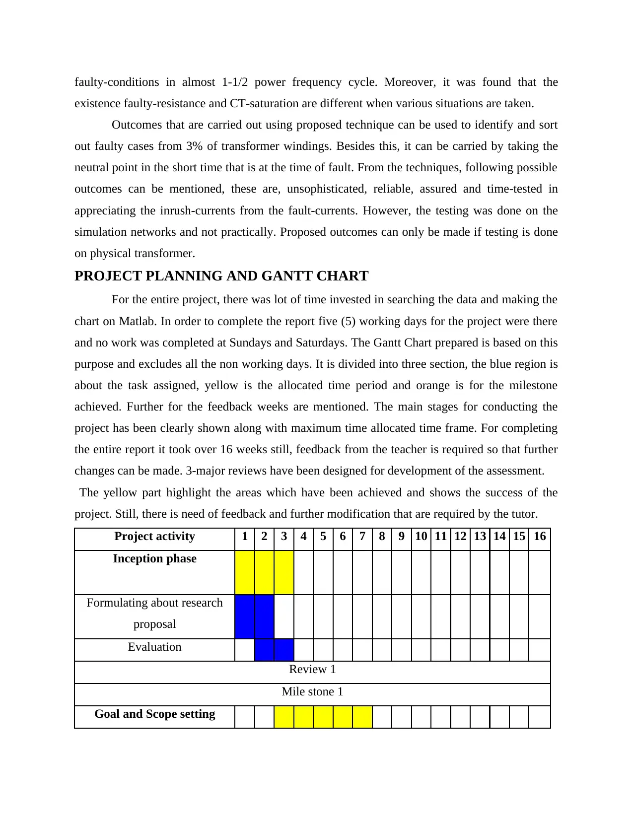
PROJECT PLANNING AND GANTT CHART
For the entire project, there was lot of time invested in searching the data and making the
chart on Matlab. In order to complete the report five (5) working days for the project were there
and no work was completed at Sundays and Saturdays. The Gantt Chart prepared is based on this
purpose and excludes all the non working days. It is divided into three section, the blue region is
about the task assigned, yellow is the allocated time period and orange is for the milestone
achieved. Further for the feedback weeks are mentioned. The main stages for conducting the
project has been clearly shown along with maximum time allocated time frame. For completing
the entire report it took over 16 weeks still, feedback from the teacher is required so that further
changes can be made. 3-major reviews have been designed for development of the assessment.
The yellow part highlight the areas which have been achieved and shows the success of the
project. Still, there is need of feedback and further modification that are required by the tutor.
Project activity 1 2 3 4 5 6 7 8 9 10 11 12 13 14 15 16
Inception phase
Formulating about research
proposal
Evaluation
Review 1
Mile stone 1
Goal and Scope setting
existence faulty-resistance and CT-saturation are different when various situations are taken.
Outcomes that are carried out using proposed technique can be used to identify and sort
out faulty cases from 3% of transformer windings. Besides this, it can be carried by taking the
neutral point in the short time that is at the time of fault. From the techniques, following possible
outcomes can be mentioned, these are, unsophisticated, reliable, assured and time-tested in
appreciating the inrush-currents from the fault-currents. However, the testing was done on the
simulation networks and not practically. Proposed outcomes can only be made if testing is done
on physical transformer.
PROJECT PLANNING AND GANTT CHART
For the entire project, there was lot of time invested in searching the data and making the
chart on Matlab. In order to complete the report five (5) working days for the project were there
and no work was completed at Sundays and Saturdays. The Gantt Chart prepared is based on this
purpose and excludes all the non working days. It is divided into three section, the blue region is
about the task assigned, yellow is the allocated time period and orange is for the milestone
achieved. Further for the feedback weeks are mentioned. The main stages for conducting the
project has been clearly shown along with maximum time allocated time frame. For completing
the entire report it took over 16 weeks still, feedback from the teacher is required so that further
changes can be made. 3-major reviews have been designed for development of the assessment.
The yellow part highlight the areas which have been achieved and shows the success of the
project. Still, there is need of feedback and further modification that are required by the tutor.
Project activity 1 2 3 4 5 6 7 8 9 10 11 12 13 14 15 16
Inception phase
Formulating about research
proposal
Evaluation
Review 1
Mile stone 1
Goal and Scope setting
⊘ This is a preview!⊘
Do you want full access?
Subscribe today to unlock all pages.
Trusted by 1+ million students worldwide
1 out of 16
Related Documents


Your All-in-One AI-Powered Toolkit for Academic Success.
+13062052269
info@desklib.com
Available 24*7 on WhatsApp / Email
![[object Object]](/_next/static/media/star-bottom.7253800d.svg)
Unlock your academic potential
Copyright © 2020–2026 A2Z Services. All Rights Reserved. Developed and managed by ZUCOL.