Step-by-Step Guide to Oscilloscope Setup, Calibration & Usage

Verified

Added on  2023/06/15

|4
|676
|398
Practical Assignment
AI Summary
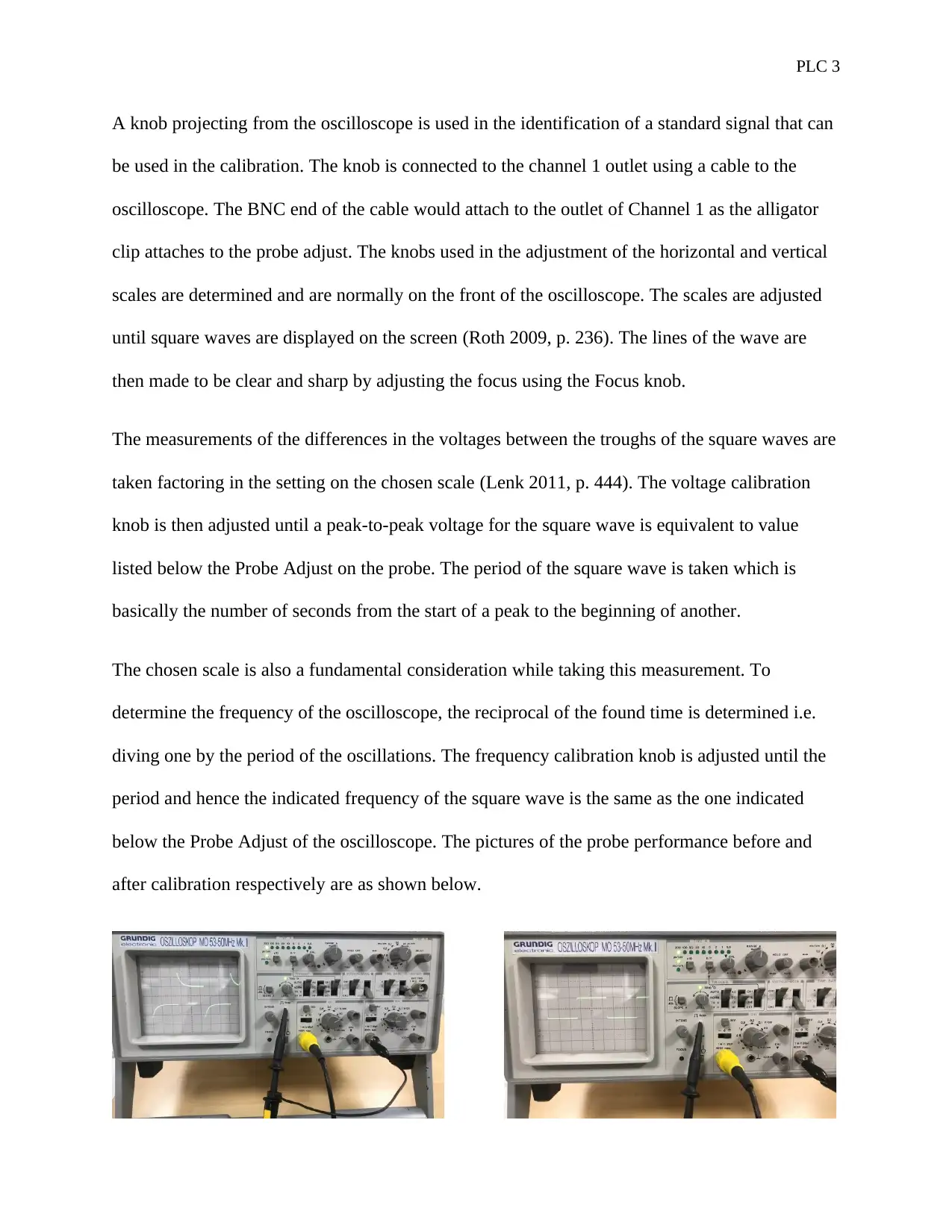
This document provides a practical guide to setting up and calibrating an oscilloscope, a fundamental tool in electronics. It outlines the general steps for setting up an oscilloscope, including examining the controls, turning on the device, setting the DIV/VOLTS and TIME controls, and connecting the probe. The document explains how an oscilloscope works by displaying signal voltage variations over time, which is crucial for circuit analysis and maintenance. The calibration process involves using a known signal strength and adjusting the device for accurate readings, utilizing knobs for horizontal and vertical scale adjustments, and focusing the display. The guide also details how to measure voltage differences, determine the period and frequency of square waves, and adjust calibration knobs for accurate peak-to-peak voltage and frequency readings. The document includes references to relevant handbooks for further reading.
Document Page
PLC 1
PLC
By Name
Course
Instructor
Institution
Location
Date
tabler-icon-diamond-filled.svg

Paraphrase This Document

Need a fresh take? Get an instant paraphrase of this document with our AI Paraphraser
Document Page
PLC 2
An oscilloscope has been found to be one of the fundamental tools that never miss application on
the workbench of electronics. Despite the high need of this tool, its affordability remains a
question that is not answerable to most of the users. It is quite expensive to afford an
oscilloscope thereby raising the need of extra vigilance when setting up and using the device. It
is of importance to every the settings of a few of the control keys of the device upon acquisition
before using the device for taking measurements (Lenk 2011, p. 698).
The steps followed in setting up an oscilloscope are not rigid but rather a factor of the type of
oscilloscope to be set up. The step is also dependent on the model of the device hence the need to
read the instructions that normally accompanies the manual. The general steps for setting up the
device include;
Examination of the controls of the scope and doing the settings to normal
Turning on the oscilloscope
Setting the DIV/VOLTS control to 1
Setting the TIME control to 1ms
Setting the Trigger Switch to Auto mode
Connection of the probe to the input connector; and finally
Touching the end of the probe to the calibration terminal of the scope
An oscilloscope works by taking the variations in the signal voltages as a function of time and
then displays the results on a screen. This information is integral in the analysis of circuits
thereby enabling repair and maintenance (Lenk 2011, p. 598). To calibrate an oscilloscope, a
voltage of known signal strength is used and then adjustments are made to the device until the
correct readings are achieved. To achieve the accurate reading;
Document Page
PLC 3
A knob projecting from the oscilloscope is used in the identification of a standard signal that can
be used in the calibration. The knob is connected to the channel 1 outlet using a cable to the
oscilloscope. The BNC end of the cable would attach to the outlet of Channel 1 as the alligator
clip attaches to the probe adjust. The knobs used in the adjustment of the horizontal and vertical
scales are determined and are normally on the front of the oscilloscope. The scales are adjusted
until square waves are displayed on the screen (Roth 2009, p. 236). The lines of the wave are
then made to be clear and sharp by adjusting the focus using the Focus knob.
The measurements of the differences in the voltages between the troughs of the square waves are
taken factoring in the setting on the chosen scale (Lenk 2011, p. 444). The voltage calibration
knob is then adjusted until a peak-to-peak voltage for the square wave is equivalent to value
listed below the Probe Adjust on the probe. The period of the square wave is taken which is
basically the number of seconds from the start of a peak to the beginning of another.
The chosen scale is also a fundamental consideration while taking this measurement. To
determine the frequency of the oscilloscope, the reciprocal of the found time is determined i.e.
diving one by the period of the oscillations. The frequency calibration knob is adjusted until the
period and hence the indicated frequency of the square wave is the same as the one indicated
below the Probe Adjust of the oscilloscope. The pictures of the probe performance before and
after calibration respectively are as shown below.
Document Page
PLC 4
References
Lenk, JD 2011, Handbook of practical electronic tests and measurements, 4th edn, Prentice-
Hall, Paris.
Roth, CH 2009, Use of the Dual-trace Oscilloscope: A Programmed Text, 3rd edn, Prentice-Hall,
New York.
chevron_up_icon
1 out of 4
circle_padding
hide_on_mobile
zoom_out_icon
[object Object]