B.Tech Project: Comprehensive Study on Pre-Engineered Buildings (PEB)
VerifiedAdded on 2022/10/10
|20
|3621
|2
Project
AI Summary
This project presents a comprehensive study on pre-engineered buildings (PEB), examining their history, features, advantages, and comparison with conventional steel buildings. It covers the design cycle, geometric configuration, loading considerations, and relevant codes and standards. A case study of metro stations in Hyderabad is included, detailing their construction phases, design parameters, and erection procedures. The project emphasizes the economy and simpler production of PEB structures compared to conventional steel buildings, referencing Indian and American codes for structural design. The use of STAAD Pro for design and analysis is highlighted, along with the benefits of PEB systems for single-story structures and their application in various fields. This document is useful for Civil Engineering students for understanding the design and application of PEB, offering insights into their construction and advantages.
COMPREHENSIVE STUDY ON
PRE-ENGINEERED BUILDINGS
A project Research for Pre- Engineered Buildings
Bachelor of Technology (Civil Engineering)
By
Firstname Lastname
1
PRE-ENGINEERED BUILDINGS
A project Research for Pre- Engineered Buildings
Bachelor of Technology (Civil Engineering)
By
Firstname Lastname
1
Paraphrase This Document
Need a fresh take? Get an instant paraphrase of this document with our AI Paraphraser
Table of Contents
ABSTRACT.............................................................................................................................................3
CHAPTER 1: INTRODUCTION......................................................................................................4
1.1. History of PEB.......................................................................................................................4
1.2. Features of PEB.....................................................................................................................5
1.3. Pros of PEBs..........................................................................................................................5
1.4. Comparing of PEB with Conventional Steel Buildings.........................................................6
CHAPTER 2: DESIGNS PEB..........................................................................................................10
2.1. Design Cycle:..........................................................................................................................10
2.2 Geometric configuration of the frame........................................................................................11
2.3 Loading on the frame.................................................................................................................11
2.4. Codes and standards for Design...............................................................................................12
2.5 Design Criteria...........................................................................................................................12
2.6. Design Process.........................................................................................................................12
CHAPTER- 3: METRO STATIONS AT HYDERABAD.........................................................13
3.1 Introduction...............................................................................................................................13
3.2 Metro Rail Systems in Hyderabad.............................................................................................13
3.2.1. Hyderabad goes Hi-Speed:.................................................................................................13
3.2.2 Background:........................................................................................................................14
3.2.3 The execution of Hyderabad...............................................................................................14
3.3 Construction Phases...................................................................................................................14
3.3.1 Phase one............................................................................................................................15
3.3.2 Phase two............................................................................................................................15
3.4 Lines..........................................................................................................................................15
3.5 Details About the Station...........................................................................................................15
3.6 Design Parameters Used in Station............................................................................................15
3.7. Erection Procedure of Station Components..............................................................................16
3.8. Metro station.............................................................................................................................16
3.8.1 Rafter..................................................................................................................................16
3.8.2. Purlins................................................................................................................................16
3.8.3 Tie Beams...........................................................................................................................17
3.8.4 Gutter..................................................................................................................................17
3.8.5 Brace Rods..........................................................................................................................17
CHAPTER 4: CONCLUSION.........................................................................................................19
References...........................................................................................................................................20
2
ABSTRACT
The advent of Pre-Engineered Building idea in structural design has assisted to
optimize design in past years. Instead (CSB) model principle, the adoptability of PEB
led to an increase in many advantages, such as economy and simpler production. This
research analyzes and designs an industrial structure (Ware House) bestowing to Indian
rules. Throughout this research, a building with a span of 187 m, 40 meters breadth
with 8 meter high and a slope of 1:10, is regarded for 20 frames (End frame, frame)
analysis & layout. In terms of its weight comparison, the economy of the structure is
discussed between Indian codes (IS800-1984, 15800-2007) & American code (MBMA-
96), & Indian codes (15800-1984, 15800-2007).
Pre-engineered buildings (PEB) is the idea of concrete structures introduced in the early
1960s. The composition here uses entire I segment and the beauty here in this notion that
no welding mechanism will be passed out on site. The entire system will be designed and
made in the shop. Here Designing a PEB construction needs IS 800-2007, IS 875-1987,
IS 1893 Design codes using STAAD Pro and explaining all parameters and design
processes.
The pre-engineered structural steel system has excellent benefits for single-story
structures, a practical and effective alternative to standard structures, with the system
representing one key model in various fields. Staad pro software correspondences for
proposal are presently being introduced by pre-engineered construction to create and
maintain multifaceted, data-rich opinions in actual time via project assistance.
3
⊘ This is a preview!⊘
Do you want full access?
Subscribe today to unlock all pages.
Trusted by 1+ million students worldwide
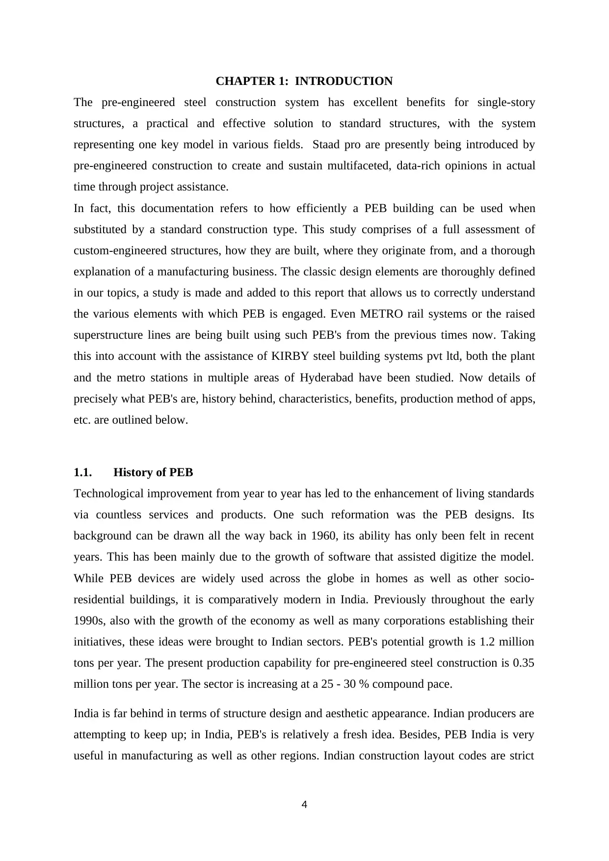
CHAPTER 1: INTRODUCTION
The pre-engineered steel construction system has excellent benefits for single-story
structures, a practical and effective solution to standard structures, with the system
representing one key model in various fields. Staad pro are presently being introduced by
pre-engineered construction to create and sustain multifaceted, data-rich opinions in actual
time through project assistance.
In fact, this documentation refers to how efficiently a PEB building can be used when
substituted by a standard construction type. This study comprises of a full assessment of
custom-engineered structures, how they are built, where they originate from, and a thorough
explanation of a manufacturing business. The classic design elements are thoroughly defined
in our topics, a study is made and added to this report that allows us to correctly understand
the various elements with which PEB is engaged. Even METRO rail systems or the raised
superstructure lines are being built using such PEB's from the previous times now. Taking
this into account with the assistance of KIRBY steel building systems pvt ltd, both the plant
and the metro stations in multiple areas of Hyderabad have been studied. Now details of
precisely what PEB's are, history behind, characteristics, benefits, production method of apps,
etc. are outlined below.
1.1. History of PEB
Technological improvement from year to year has led to the enhancement of living standards
via countless services and products. One such reformation was the PEB designs. Its
background can be drawn all the way back in 1960, its ability has only been felt in recent
years. This has been mainly due to the growth of software that assisted digitize the model.
While PEB devices are widely used across the globe in homes as well as other socio-
residential buildings, it is comparatively modern in India. Previously throughout the early
1990s, also with the growth of the economy as well as many corporations establishing their
initiatives, these ideas were brought to Indian sectors. PEB's potential growth is 1.2 million
tons per year. The present production capability for pre-engineered steel construction is 0.35
million tons per year. The sector is increasing at a 25 - 30 % compound pace.
India is far behind in terms of structure design and aesthetic appearance. Indian producers are
attempting to keep up; in India, PEB's is relatively a fresh idea. Besides, PEB India is very
useful in manufacturing as well as other regions. Indian construction layout codes are strict
4
Paraphrase This Document
Need a fresh take? Get an instant paraphrase of this document with our AI Paraphraser
but safer compared to many other countries. IS criteria are continually being updated.
American standards are also being pursued in India.
1.2. Features of PEB
In fact, PEB metal structures can be equipped with various structural parts as well as floors,
balconies, fascia, interior partitions etc. and the building is made waterproof using unique
mastic beads, filler strips and trimmings. These are highly versatile building technologies and
can be completed outward to fulfill any tasks and centrally intended to accomplish appealing
and distinctive design styles. It's really valuable in sophisticated buildings or in the low-rise
building this is very beneficial.
The first and most common and economical type of low-rise constructions is a building with
a ground level and two upper floors and as well as a roof. The construction roof at low height
can be flat or sloping. Optimal low-rise floors are made from mezzanine buildings.
Construction of lone-storied structures needs minimal construction time and can be
constructed in any type of geographical proximity, such as cold weather mountainous areas,
high precipitation-prone areas, plain soil, transparent and thrilling cold climate sectors.
1.3. Pros of PEBs
Time reduction during construction: Normally, in the next few weeks of building
authorization, structures are provided. In combination with finished bolts, base and
anchor bolts are cast available to bolt the site.
Reduced cost of construction: The price of modelling, constructing and site
formation is considerably decreased due to the system approach. In order to decrease
transport costs, the tertiary respondents and structural steel nest together.
Room for expansion: By incorporating additional bays, buildings can be easily
expanded.
Adequate open distance: houses with a clear distance length of about 80 meters can
be supplied.
Room for quality control: Performance is assured as it is under controlled conditions
buildings are completely manufactured in the plant.
Low or minimal maintenance cost
5
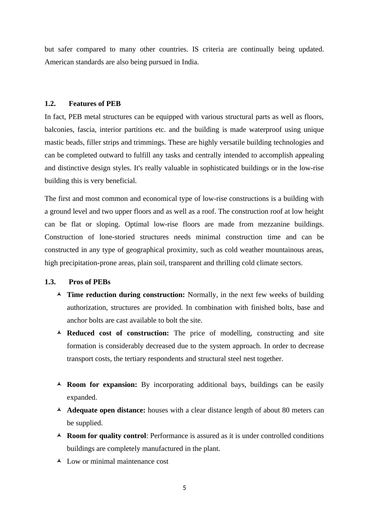
Efficiency in roofing and walling systems in terms of energy required
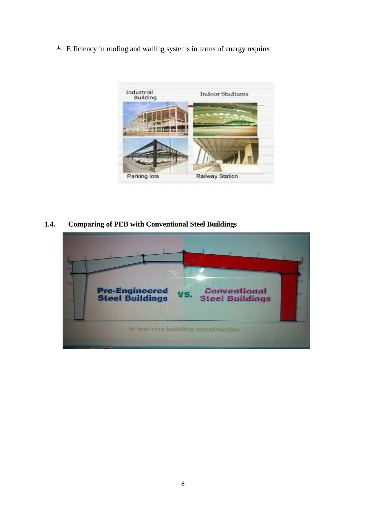
1.4. Comparing of PEB with Conventional Steel Buildings
6
1.4. Comparing of PEB with Conventional Steel Buildings
6
⊘ This is a preview!⊘
Do you want full access?
Subscribe today to unlock all pages.
Trusted by 1+ million students worldwide
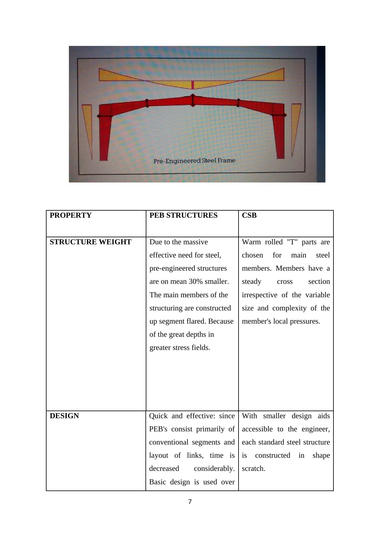
PROPERTY PEB STRUCTURES CSB
STRUCTURE WEIGHT Due to the massive
effective need for steel,
pre-engineered structures
are on mean 30% smaller.
The main members of the
structuring are constructed
up segment flared. Because
of the great depths in
greater stress fields.
Warm rolled "T" parts are
chosen for main steel
members. Members have a
steady cross section
irrespective of the variable
size and complexity of the
member's local pressures.
DESIGN Quick and effective: since
PEB's consist primarily of
conventional segments and
layout of links, time is
decreased considerably.
Basic design is used over
With smaller design aids
accessible to the engineer,
each standard steel structure
is constructed in shape
scratch.
7
Paraphrase This Document
Need a fresh take? Get an instant paraphrase of this document with our AI Paraphraser
and over based on global
design codes.
Specialized design
programs for software
analysis optimize the
necessary material. Using
normal information to
reduce the need for custom
project information, current
draft is also automated.
The advisor with lesser
design aids requires
significant engineering and
detailed job since the very
basic requirement.
The automaker offers
unlimited designs of the
design shop details and
sketches of the erection. It
usually requires two weeks
to train for authorization
drawing. Nevertheless, pre-
engineered structures
engineers’ model and
outline PEB structures
almost every day, improve
the quality of design
anytime they work.
The duration of a detailed
consultant is devoted to the
modifications that still need
to be created.
8
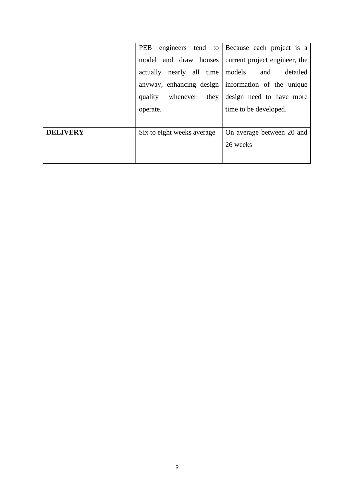
PEB engineers tend to
model and draw houses
actually nearly all time
anyway, enhancing design
quality whenever they
operate.
Because each project is a
current project engineer, the
models and detailed
information of the unique
design need to have more
time to be developed.
DELIVERY Six to eight weeks average On average between 20 and
26 weeks
9
⊘ This is a preview!⊘
Do you want full access?
Subscribe today to unlock all pages.
Trusted by 1+ million students worldwide
CHAPTER 2: DESIGNS PEB
The method of shear matrix analyses the main framing of PEB models. The model is cantered
on permitted stress design (ASD) according to the ASCI or standards as per IS 800. The setup
system offers an optimal and money-effective modelling of the primary girders and enables
the use of the program in variety of systems to create the geometry and packaging of the
frame model and the necessary load settings as detailed in the building codes of customer.
The software functions to achieve a suitable design by the highest number of cycles. The
scheme utilizes the technique of the torsional vector to obtain a suitable model. The program
utilizes the technique of the hardness matrix to reach the acceleration and stresses response.
To measure the set end moments, rigidity and hold factors, the strain energy technique is
implemented. There is use of mathematical assimilation.
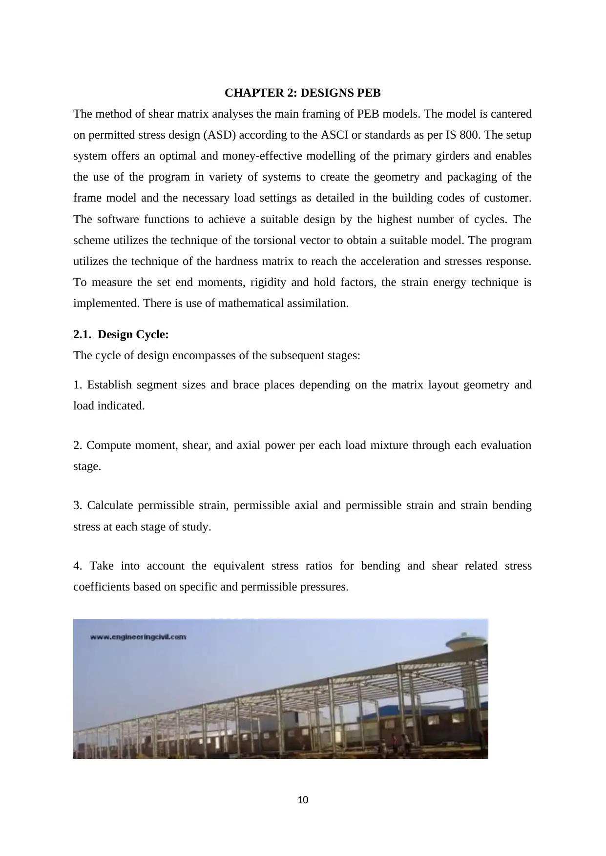
2.1. Design Cycle:
The cycle of design encompasses of the subsequent stages:
1. Establish segment sizes and brace places depending on the matrix layout geometry and
load indicated.
2. Compute moment, shear, and axial power per each load mixture through each evaluation
stage.
3. Calculate permissible strain, permissible axial and permissible strain and strain bending
stress at each stage of study.
4. Take into account the equivalent stress ratios for bending and shear related stress
coefficients based on specific and permissible pressures.
10
The method of shear matrix analyses the main framing of PEB models. The model is cantered
on permitted stress design (ASD) according to the ASCI or standards as per IS 800. The setup
system offers an optimal and money-effective modelling of the primary girders and enables
the use of the program in variety of systems to create the geometry and packaging of the
frame model and the necessary load settings as detailed in the building codes of customer.
The software functions to achieve a suitable design by the highest number of cycles. The
scheme utilizes the technique of the torsional vector to obtain a suitable model. The program
utilizes the technique of the hardness matrix to reach the acceleration and stresses response.
To measure the set end moments, rigidity and hold factors, the strain energy technique is
implemented. There is use of mathematical assimilation.
2.1. Design Cycle:
The cycle of design encompasses of the subsequent stages:
1. Establish segment sizes and brace places depending on the matrix layout geometry and
load indicated.
2. Compute moment, shear, and axial power per each load mixture through each evaluation
stage.
3. Calculate permissible strain, permissible axial and permissible strain and strain bending
stress at each stage of study.
4. Take into account the equivalent stress ratios for bending and shear related stress
coefficients based on specific and permissible pressures.
10
Paraphrase This Document
Need a fresh take? Get an instant paraphrase of this document with our AI Paraphraser
5. Layout the best joint location and crisscross to understand if production limitations are
confirmed by the expected dimensions.
6. To use the internet improvement mode, reach for the next cycle at the optimal web lengths
and update the member information file.
7. An assessment is performed at the beginning of all design cycles to accomplish
improvement of the flange brace.
2.2 Geometric configuration of the frame
The system is able to improve distinct kinds of matrix geometry as described
Rigid frames, full-column frames, single frames of incline, narrow frames, etc.
Frames of various lengths, slopes and elevations, and so on.
Asymmetric frames with components off-centre, various routes.
Purlin and flange brace position stated by the client.
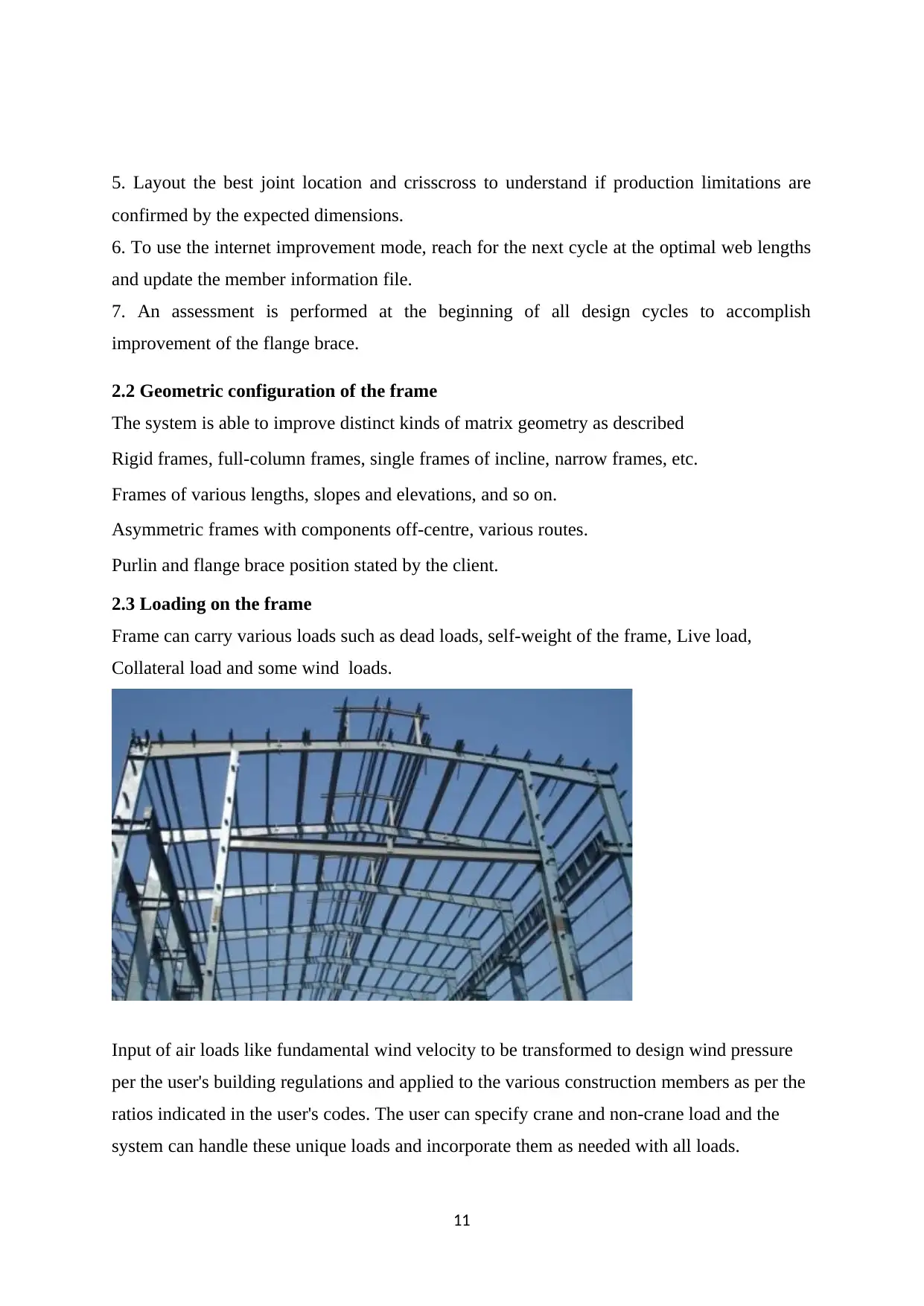
2.3 Loading on the frame
Frame can carry various loads such as dead loads, self-weight of the frame, Live load,
Collateral load and some wind loads.
Input of air loads like fundamental wind velocity to be transformed to design wind pressure
per the user's building regulations and applied to the various construction members as per the
ratios indicated in the user's codes. The user can specify crane and non-crane load and the
system can handle these unique loads and incorporate them as needed with all loads.
11
confirmed by the expected dimensions.
6. To use the internet improvement mode, reach for the next cycle at the optimal web lengths
and update the member information file.
7. An assessment is performed at the beginning of all design cycles to accomplish
improvement of the flange brace.
2.2 Geometric configuration of the frame
The system is able to improve distinct kinds of matrix geometry as described
Rigid frames, full-column frames, single frames of incline, narrow frames, etc.
Frames of various lengths, slopes and elevations, and so on.
Asymmetric frames with components off-centre, various routes.
Purlin and flange brace position stated by the client.
2.3 Loading on the frame
Frame can carry various loads such as dead loads, self-weight of the frame, Live load,
Collateral load and some wind loads.
Input of air loads like fundamental wind velocity to be transformed to design wind pressure
per the user's building regulations and applied to the various construction members as per the
ratios indicated in the user's codes. The user can specify crane and non-crane load and the
system can handle these unique loads and incorporate them as needed with all loads.
11
It is also possible to define and combine earthquake loads conforming to the distinct area
classifications of distinct global codes for all load instances as needed. Heat loads can even
be defined by stipulating the suitable coefficient for temperature change in the manner of
distinct average temperature value on Celsius. The user may specify load variations with
suitable load variables as required.
2.4. Codes and standards for Design
Following are the main design codes generally used:
UBC, AISC, ANSI, ASCE, IS, AISI, MBMA
2.5 Design Criteria
2.5.1 Design Method: the procedure of permissible stress design is being used according to
the requirements of the AISC.
2.5.2 Deflections: MBMA, AISC criteria and normal sector procedures shall be subject to
interceptions unless otherwise indicated.
2.5.3. Main Framing: Momentary frame resistance with attached or fixed borders.
2.5.4 Tertiary Framing: Either Z or C -sections intended as constant frames covering roof
and lap columns.
2.5.5 longitudinal Stability: wind loads on the end walls of the construction are transmitted
to articulated bays via roof purlins and diagonally braced to the foundations.
2.5.6 Software Design: the recent software used to design is STAAD 2007.
2.6. Design Process
On this basis, the information is collected and the characteristics of the member segment are
calculated. Taking into account all feasible displacements, the general combined stiffness
matrix is achieved depending on that frame information by summing individual stiffness
matrices.
12
⊘ This is a preview!⊘
Do you want full access?
Subscribe today to unlock all pages.
Trusted by 1+ million students worldwide
1 out of 20
Your All-in-One AI-Powered Toolkit for Academic Success.
+13062052269
info@desklib.com
Available 24*7 on WhatsApp / Email
![[object Object]](/_next/static/media/star-bottom.7253800d.svg)
Unlock your academic potential
Copyright © 2020–2026 A2Z Services. All Rights Reserved. Developed and managed by ZUCOL.