Embedded System Design: Prepaid Energy Meter with GSM Communication
VerifiedAdded on 2022/08/27
|13
|2660
|26
Project
AI Summary
This project details the design and implementation of an automated prepaid energy meter system, aiming to eliminate the need for manual meter reading and improve energy billing efficiency. The system utilizes an AT89S52 microcontroller to gather data, a smart card for credit limits, and a GSM module for communication between the service provider and the consumer. The project includes a Java-based front-end for data management and SMS communication. The system incorporates a power supply with a transformer, bridge rectifier, and voltage regulator. Key components include an EEPROM, GPRS modem, ADC0808, and an LCD display. The project's advantages include accurate billing, time-saving, flexibility, easy meter top-up, home energy display, and reduced energy theft. The report provides detailed circuit diagrams, component descriptions, and block diagrams to illustrate the system's functionality. The objective is to minimize queues in billing centers, cut off power automatically for non-payment, and reduce power loss and theft, thereby improving energy management and customer service.

1
Prepaid Energy Meter
Student’s Name
Institutional Affiliation
Date
Prepaid Energy Meter
Student’s Name
Institutional Affiliation
Date
Paraphrase This Document
Need a fresh take? Get an instant paraphrase of this document with our AI Paraphraser
2
Abstract
Since the distribution of electrical energy began, the conventional billing method has been to
send a company representative to read the energy meters (for water or electrical energy) and
provide the information to the customer to make the necessary payments. This approach is
inefficient and time wasting since the individual has to travel from area to area going from
house to house to take readings. This represents a significant amount of time and resources
wasted since the board or energy authority has to send its employees who also have other
duties to perform. To overcome this problem and improve the effectiveness and efficiency of
service delivery, this project investigated the automation of the energy billing system for
water and electricity to eliminate the need for individual meter reading. The project was
designed to be user friendly and easy to operate to enable customers and employees to use the
system without specialized training. Java was used for the front end design.
Table of Contents
Table of figures......................................................................................................................................2
Abstract.................................................................................................................................................2
Introduction...........................................................................................................................................3
Working.............................................................................................................................................3
Circuit diagram..................................................................................................................................4
Description of the circuit...................................................................................................................4
Circuit explanation.............................................................................................................................5
Block diagram....................................................................................................................................6
System advantages............................................................................................................................6
Description of the components.............................................................................................................7
Conclusion...........................................................................................................................................12
Bibliography.........................................................................................................................................13
Table of figures
Figure 1: Complete circuit diagram........................................................................................................4
Figure 2: Circuit breakdown..................................................................................................................5
Figure 3: System block diagram.............................................................................................................6
Figure 4: AT89S52 microcontroller........................................................................................................8
Figure 5: EEPROM AT24C02...................................................................................................................9
Figure 6: DSM modem.........................................................................................................................10
Figure 7: ADC0808 chip.......................................................................................................................11
Figure 8: LCD display............................................................................................................................11
Figure 9: BC546 transistor pinout........................................................................................................12
3
Introduction
The objective of this project is to minimize the long queues normally witnessed in
billing centers. The designed system is also required to cut-off the power supply to the
customer automatically if the bill is not settled. Additionally, the project aims to minimize
power loss and power theft which leads to loss of revenue for the government. To fully
implement this project, GSM technology is incorporated to enable communication between
the service provider and the consumer in terms of energy consumption in units. If the number
of units gets too low, the sytstem is designed to alert the user to recharge. This technology
can be adopted by all power distribution companies, self-contained housing projects, and
private communities. The adoption of this strategy will yield better energy management,
minimize losses, save time and minimize customer overcharging due to incorrect meter
reading. This system enables real time tracking of consumption which leaves little room for
billing errors.
Working
The primary controller in this system is the AT89S52 microcontroller. One of its functions is
to gather data from the consumption meter and the smart card. Switches are used here to
replace the IC. The smart card which acts as the switch provides information regarding the
limit of the available units. The microcontroller compares the reading on the energy meter
with the information on the smart card. The microcontroller then triggers a buzzer if the card
credit is low. If the credit falls below a certain threshold, the microcontroller activates a relay
whose function is to cut-off and restore power. A parallel port connection is used to interface
the microcontroller with the LCD screen. This microcontroller-based system continuously
monitors the readings, greatly increasing the efficiency and accuracy in computation of bills
and reducing human intervention. The system can notify the consumer about the balance of
the credit via the GSM module which is connected serially with the microcontroller. The
programming utilizes the GSM’s messaging features via the AT command. The GSM utilizes
its own communication network. Low credit triggers the relay which shuts down power to be
restored only when the meter is recharged. Java Basics software is the main software used as
a platform to develop the application for sending or receiving SMS via the modem,
processing and storing data. The software is meant to perform two major tasks,
i) To maintain the database
ii) To interact with the modem and to read the COM port
This project explores the interface of a microcontroller and a GSM module with an energy
meter in each house. Each house has an energy meter with a unique identity provided by the
service provider. The microcontroller and GSM module are incorporated into the energy
meter. The energy consumption data is stored in the form of SMS in the microcontroller. This
SMS can then be sent to the specific number assigned by the provider. The transmitted
message is received by the modem on the other end as a command which directs the
microcontroller to compute the readings. The controller then sends the results to the modem
which transmits the information back to the provider control center where the Java software
⊘ This is a preview!⊘
Do you want full access?
Subscribe today to unlock all pages.
Trusted by 1+ million students worldwide
4
calculates the total consumption. This process is very fast and saves time and illegal power
consumption.
Circuit diagram
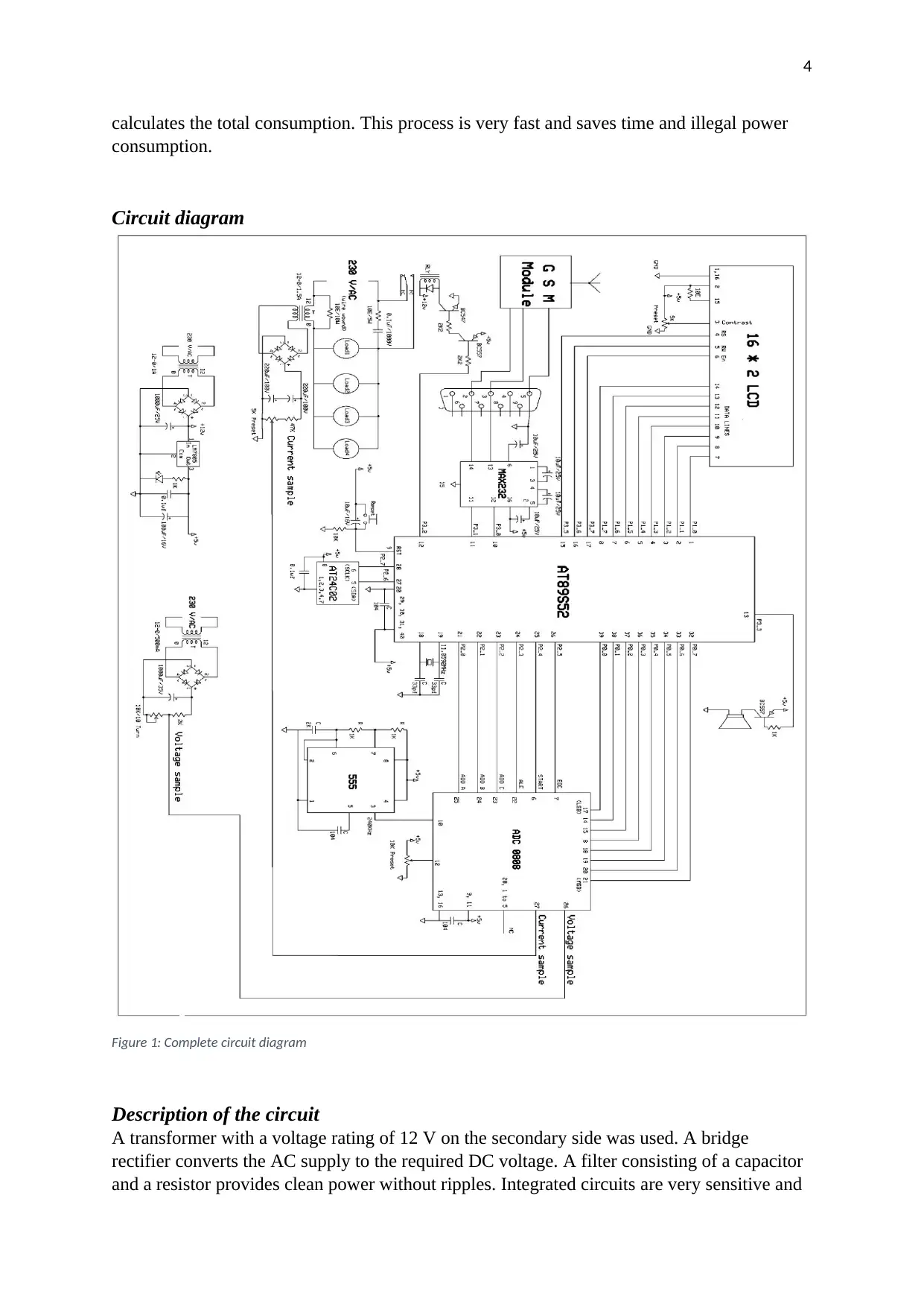
Figure 1: Complete circuit diagram
Description of the circuit
A transformer with a voltage rating of 12 V on the secondary side was used. A bridge
rectifier converts the AC supply to the required DC voltage. A filter consisting of a capacitor
and a resistor provides clean power without ripples. Integrated circuits are very sensitive and
calculates the total consumption. This process is very fast and saves time and illegal power
consumption.
Circuit diagram
Figure 1: Complete circuit diagram
Description of the circuit
A transformer with a voltage rating of 12 V on the secondary side was used. A bridge
rectifier converts the AC supply to the required DC voltage. A filter consisting of a capacitor
and a resistor provides clean power without ripples. Integrated circuits are very sensitive and
Paraphrase This Document
Need a fresh take? Get an instant paraphrase of this document with our AI Paraphraser
5
require a very stable DC supply. For steady voltage, an LM7805 voltage regulator is
employed to provide a stable DC voltage of 5 V.
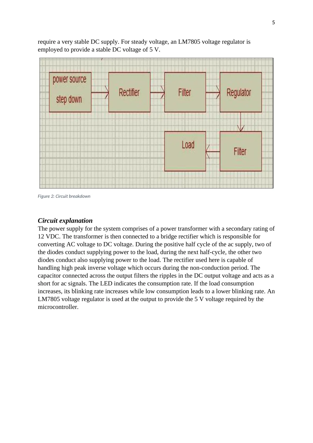
Figure 2: Circuit breakdown
Circuit explanation
The power supply for the system comprises of a power transformer with a secondary rating of
12 VDC. The transformer is then connected to a bridge rectifier which is responsible for
converting AC voltage to DC voltage. During the positive half cycle of the ac supply, two of
the diodes conduct supplying power to the load, during the next half-cycle, the other two
diodes conduct also supplying power to the load. The rectifier used here is capable of
handling high peak inverse voltage which occurs during the non-conduction period. The
capacitor connected across the output filters the ripples in the DC output voltage and acts as a
short for ac signals. The LED indicates the consumption rate. If the load consumption
increases, its blinking rate increases while low consumption leads to a lower blinking rate. An
LM7805 voltage regulator is used at the output to provide the 5 V voltage required by the
microcontroller.
require a very stable DC supply. For steady voltage, an LM7805 voltage regulator is
employed to provide a stable DC voltage of 5 V.
Figure 2: Circuit breakdown
Circuit explanation
The power supply for the system comprises of a power transformer with a secondary rating of
12 VDC. The transformer is then connected to a bridge rectifier which is responsible for
converting AC voltage to DC voltage. During the positive half cycle of the ac supply, two of
the diodes conduct supplying power to the load, during the next half-cycle, the other two
diodes conduct also supplying power to the load. The rectifier used here is capable of
handling high peak inverse voltage which occurs during the non-conduction period. The
capacitor connected across the output filters the ripples in the DC output voltage and acts as a
short for ac signals. The LED indicates the consumption rate. If the load consumption
increases, its blinking rate increases while low consumption leads to a lower blinking rate. An
LM7805 voltage regulator is used at the output to provide the 5 V voltage required by the
microcontroller.
6
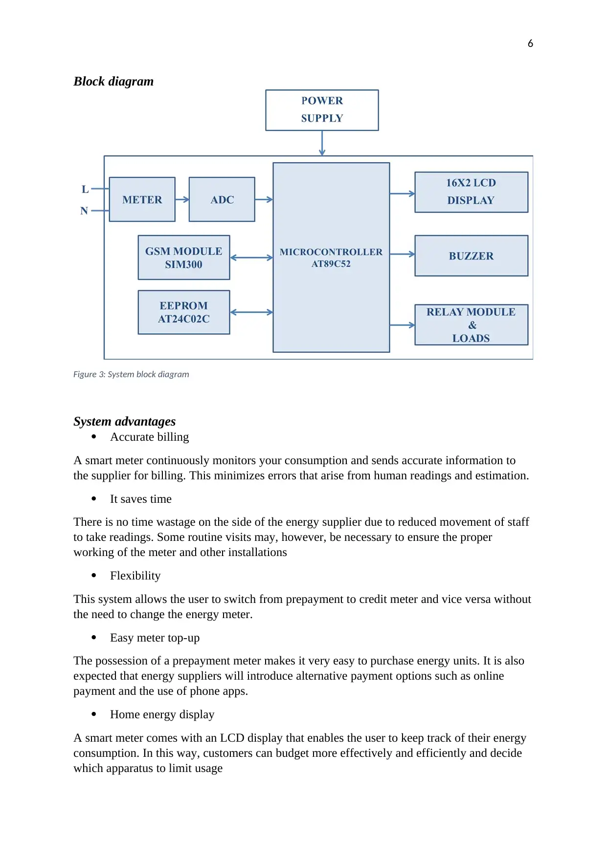
Block diagram
Figure 3: System block diagram
System advantages
Accurate billing
A smart meter continuously monitors your consumption and sends accurate information to
the supplier for billing. This minimizes errors that arise from human readings and estimation.
It saves time
There is no time wastage on the side of the energy supplier due to reduced movement of staff
to take readings. Some routine visits may, however, be necessary to ensure the proper
working of the meter and other installations
Flexibility
This system allows the user to switch from prepayment to credit meter and vice versa without
the need to change the energy meter.
Easy meter top-up
The possession of a prepayment meter makes it very easy to purchase energy units. It is also
expected that energy suppliers will introduce alternative payment options such as online
payment and the use of phone apps.
Home energy display
A smart meter comes with an LCD display that enables the user to keep track of their energy
consumption. In this way, customers can budget more effectively and efficiently and decide
which apparatus to limit usage
⊘ This is a preview!⊘
Do you want full access?
Subscribe today to unlock all pages.
Trusted by 1+ million students worldwide

7
Extra services
Some service providers offer additional information regarding energy usage to help their
customers manage their consumption more easily.
Saves money
Since consumers are aware of their consumption according to the meter readings, they can
reduce energy consumption by identifying equipment with the highest consumption.
Benefits from different tariffs
Consumers may benefit from various tariffs which may offer better tariffs or rewards for
consumption at specific day times.
Reduced energy theft
Energy meters enable power providers to detect fraudulent activities more easily reducing the
loss of revenue.
Rapid problem resolution
Smart meters make it easier to detect and identify technical problems and faults within the
supply system. This translates to less inconvenience due to fast response and problem fixing.
Components
i) AT89S52
ii) IC 555 timer
iii) BC547 transistor
iv) BC557 transistor
v) EEPROM AT24C02
vi) Prepaid GPRS modem
vii) ADC0808
viii) LCD 2×16
Description of the components
AT89S52
Paraphrase This Document
Need a fresh take? Get an instant paraphrase of this document with our AI Paraphraser

8
Figure 4: AT89S52 microcontroller
Description
This is a low power CMOS 8-bit microcontroller which has an in-system Flash memory of 8
KB that is programmable. This microcontroller is offered by Atmel and is produced using
high-density non-volatile memory technology. The chip is compatible with 80C51 pinout and
instruction set which is the industry standard. The chip can be reprogrammed using a
standard programmer for non-volatile memories or reprogrammed in-system. The versatility
and power of the AT89S52 are derived from its combination of an in-system programmable
Flash with an 8-bit CPU on a single monolithic chip. This allows the chip to offer cost-
effective and highly flexible solutions to many embedded system applications. The AT89S52
offers the following features,
Features
i) Operating voltage in the range of 4.0 to 5.5 V
ii) Compatibility with MCS-51® products
iii) 256×8-bit internal RAM
iv) Fully static operation from 0 Hz to 33 MHz
v) 8 KB of in-system programmable (ISP) flash memory with 1000 write/erase cycle
endurance
vi) Three-level program memory lock
vii) 32 programmable I/O lines
viii) 8 interrupt sources
ix) 3 6-bit timers/counters
x) Low power idle and power-down modes
xi) Full-duplex UART Serial channel
xii) Fast programming time
xiii) Watchdog timer
xiv) Power-off flag
xv) Flexible ISP programming
xvi) Interrupt recovery from power-down mode
xvii) Dual data pointer
EEPROM AT24C02
9
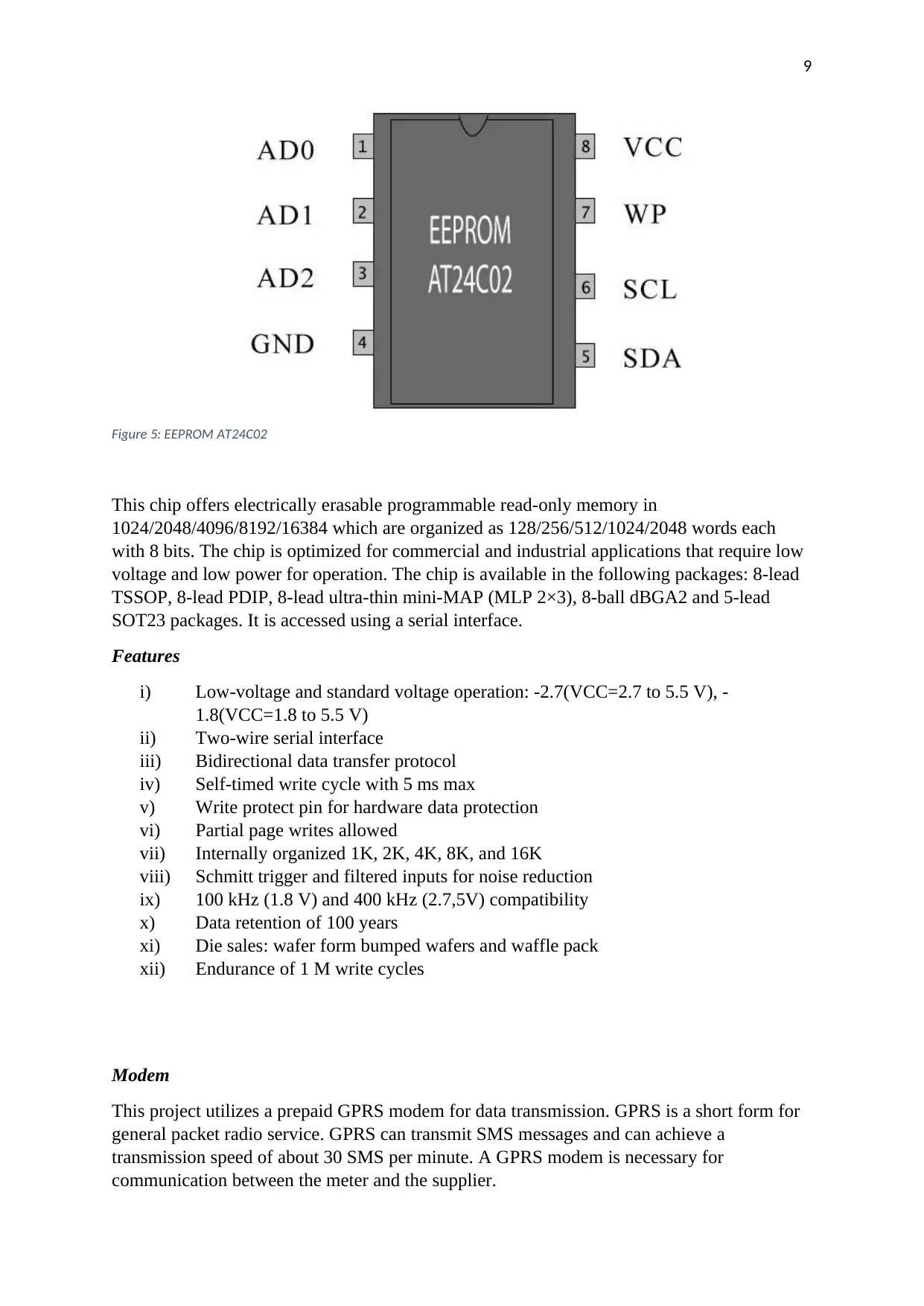
Figure 5: EEPROM AT24C02
This chip offers electrically erasable programmable read-only memory in
1024/2048/4096/8192/16384 which are organized as 128/256/512/1024/2048 words each
with 8 bits. The chip is optimized for commercial and industrial applications that require low
voltage and low power for operation. The chip is available in the following packages: 8-lead
TSSOP, 8-lead PDIP, 8-lead ultra-thin mini-MAP (MLP 2×3), 8-ball dBGA2 and 5-lead
SOT23 packages. It is accessed using a serial interface.
Features
i) Low-voltage and standard voltage operation: -2.7(VCC=2.7 to 5.5 V), -
1.8(VCC=1.8 to 5.5 V)
ii) Two-wire serial interface
iii) Bidirectional data transfer protocol
iv) Self-timed write cycle with 5 ms max
v) Write protect pin for hardware data protection
vi) Partial page writes allowed
vii) Internally organized 1K, 2K, 4K, 8K, and 16K
viii) Schmitt trigger and filtered inputs for noise reduction
ix) 100 kHz (1.8 V) and 400 kHz (2.7,5V) compatibility
x) Data retention of 100 years
xi) Die sales: wafer form bumped wafers and waffle pack
xii) Endurance of 1 M write cycles
Modem
This project utilizes a prepaid GPRS modem for data transmission. GPRS is a short form for
general packet radio service. GPRS can transmit SMS messages and can achieve a
transmission speed of about 30 SMS per minute. A GPRS modem is necessary for
communication between the meter and the supplier.
⊘ This is a preview!⊘
Do you want full access?
Subscribe today to unlock all pages.
Trusted by 1+ million students worldwide

10
Figure 6: DSM modem
Features
i) Operating temperature: -20 to +55 degrees celsius
ii) GPRS mobile station class B
iii) Compliant with GSM phase 2/2+
iv) Has 4 bands 850/900/1800/1900
v) Allows control using AT commands
vi) GPRS multi-slot 10
ADC08088
This is an 8-bit analog to digital converter consisting of 8 analog input channels. The device
has three address lines that can be used to select the input to be converted to digital form. The
Vref+ and Vref- pins are used to set the reference voltage. The set reference voltage also
determines the step size which is the change in the analog input which is necessary to yield a
unit change in the output of the ADC. The default reference voltage is 5 V which gives a step
size of about 19.53 mV. Unlike the ADC0804, this device requires an external clock to
operate. Some specific control signals are required to enable the ADC to start its operation.
The end of conversion of an analog input is signaled when the EOC pin goes low.
Paraphrase This Document
Need a fresh take? Get an instant paraphrase of this document with our AI Paraphraser
11
Figure 7: ADC0808 chip
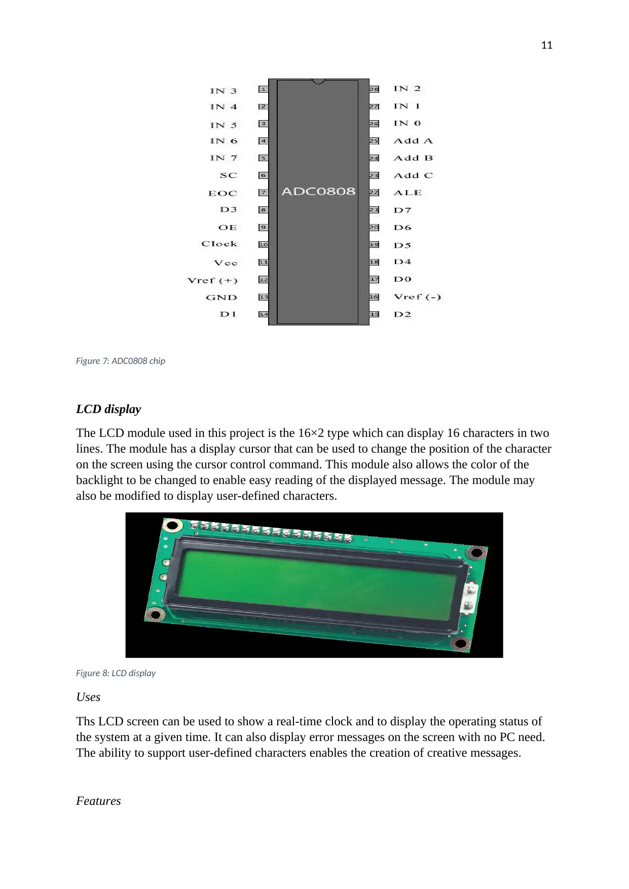
LCD display
The LCD module used in this project is the 16×2 type which can display 16 characters in two
lines. The module has a display cursor that can be used to change the position of the character
on the screen using the cursor control command. This module also allows the color of the
backlight to be changed to enable easy reading of the displayed message. The module may
also be modified to display user-defined characters.
Figure 8: LCD display
Uses
Ths LCD screen can be used to show a real-time clock and to display the operating status of
the system at a given time. It can also display error messages on the screen with no PC need.
The ability to support user-defined characters enables the creation of creative messages.
Features
Figure 7: ADC0808 chip
LCD display
The LCD module used in this project is the 16×2 type which can display 16 characters in two
lines. The module has a display cursor that can be used to change the position of the character
on the screen using the cursor control command. This module also allows the color of the
backlight to be changed to enable easy reading of the displayed message. The module may
also be modified to display user-defined characters.
Figure 8: LCD display
Uses
Ths LCD screen can be used to show a real-time clock and to display the operating status of
the system at a given time. It can also display error messages on the screen with no PC need.
The ability to support user-defined characters enables the creation of creative messages.
Features

12
i) Supports user-defined characters
ii) Allows backlight control
iii) Allows display of corresponding characters in ASCII code
iv) The module automatically converts and displays data according to its type
v) Allows tab function with cursor position assignment.
The BC546/547 transistors
Figure 9: BC546 transistor pinout
Features
i) Low noise
ii) High voltage: VCEO = 65 V
Conclusion
Traditional methods of energy billing have been shown to be ineffective, inefficient and time-
consuming. Resources are wasted through the movement of staff from region to region to
take manual readings from meters. In this project, a modern approach using electronic
components and remote communication has been implemented. This enables automatic
reading and of consumption and billing which minimizes human intervention, thus
minimizing errors and wastage of resources and revenue. The smart meter makes energy
billing and management easy and effective. Consumers can decide how to manage their
power consumption based on real-time data.
⊘ This is a preview!⊘
Do you want full access?
Subscribe today to unlock all pages.
Trusted by 1+ million students worldwide
1 out of 13
Related Documents


Your All-in-One AI-Powered Toolkit for Academic Success.
+13062052269
info@desklib.com
Available 24*7 on WhatsApp / Email
![[object Object]](/_next/static/media/star-bottom.7253800d.svg)
Unlock your academic potential
Copyright © 2020–2026 A2Z Services. All Rights Reserved. Developed and managed by ZUCOL.