Research Report: Pressurized Cooling Systems for IC Engines
VerifiedAdded on 2022/10/19
|9
|1641
|69
Report
AI Summary
This report investigates pressurized cooling systems for internal combustion engines, comparing the effectiveness of water and a water-ethylene glycol mixture as coolants. The research involves running IC engines with both coolants, observing their performance, and calculating thermal efficiency, density, and specific heat. The report discusses background research on engine operating temperatures and coolant properties, highlighting the advantages of ethylene glycol in raising boiling points. The methodology includes operation and observation phases, detailing viscosity, heat capacity, and density calculations. The analysis focuses on the impact of coolant changes on engine thermal efficiency and the core requirements of an effective cooling system. The conclusion emphasizes the importance of pressurized systems in enhancing heat transfer and maintaining optimal engine temperatures. Safety issues related to engine operation and heat emission are also addressed. The report provides a timeline of the research process and references relevant literature.
PRESSURIZED COOLING SYSTEM 1
RESEARCH ON PRESSURIZED COOLING SYSTEM FOR AN INTERNAL COMBUSTION
ENGINE
By Name
Institution
Name
Course
:
RESEARCH ON PRESSURIZED COOLING SYSTEM FOR AN INTERNAL COMBUSTION
ENGINE
By Name
Institution
Name
Course
:
Paraphrase This Document
Need a fresh take? Get an instant paraphrase of this document with our AI Paraphraser
PRESSURIZED COOLING SYSTEM 2
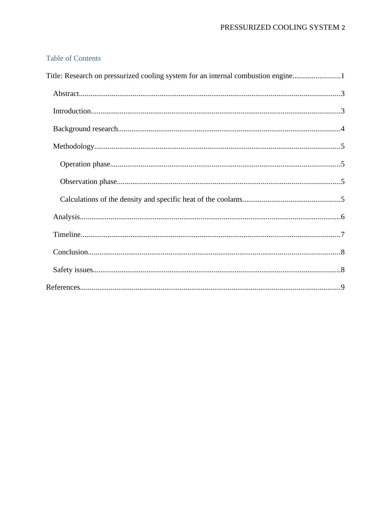
Table of Contents
Title: Research on pressurized cooling system for an internal combustion engine.........................1
Abstract........................................................................................................................................3
Introduction..................................................................................................................................3
Background research....................................................................................................................4
Methodology................................................................................................................................5
Operation phase........................................................................................................................5
Observation phase....................................................................................................................5
Calculations of the density and specific heat of the coolants...................................................5
Analysis........................................................................................................................................6
Timeline.......................................................................................................................................7
Conclusion...................................................................................................................................8
Safety issues.................................................................................................................................8
References........................................................................................................................................9
PRESSURIZED COOLING SYSTEM 3
Abstract
An internal combustion engine uses either air or liquid as a medium for removing excess heat
from the internal engine; and all combustion engines need cooling systems since burning of fuel
takes place within the engine itself. A system which is air cooled is majorly used in the small
engine. Contrary to liquid cooled system which is more efficient. This research discusses more
on a pressurized liquid system being a more effective alternative for cooling combustion engines.
Such a system involves a circulating system, pressure cap and convectional radiator. A pressure
cap has a vacuum and pressure relief valve elements which functions in reducing the maximum
operating pressure of that system as well as reducing negative pressures in order to prevent
damages while cooling after shutting down the engine (Ganesan, 2012). Pressure relief valves
also feature in such type of system, where they work hand in hand with the pressure cap
managing pressure within the system.
Introduction
The Liquid cooled systems are the most used systems these days. With this system in an
automotive, heat is driven off by using heat absorbing coolant which circulates throughout the
internal engine, most likely around the chamber of combustion particularly in the cylinder head
region of the engine block (Moroi et al, 2000). This coolant is then pumped through the engine,
where it absorbs the heat obtained during combustion, thereafter circulating to the radiator where
the excess heat is ultimately passed to the atmosphere. After cooling the liquid, it is then brought
back to the engine where a similar process is repeated.
.
Research will involve;
⊘ This is a preview!⊘
Do you want full access?
Subscribe today to unlock all pages.

Trusted by 1+ million students worldwide
PRESSURIZED COOLING SYSTEM 4
Running two IC (internal combustion) engines using a water coolant and the other using a
mixture of water and antifreeze (ethylene glycol)
Observing the outcome of the two engines
Calculating the thermal efficiency, density and specific heat of the coolants
Preparing a report
Background research
Engines operate in a wide range of temperatures, from below the freezing point to well above
100 degrees centigrade. The most suitable fluid to be used in cooling the engine must possess a
very high boiling point, a very low freezing point and it must be capable of holding more heat. In
this research, we will compare two liquids for cooling; pure water and a mixture of ethylene
glycol and water. Water is one of the efficient liquids with a capability of holding heat, though it
freezes at a temperature which is much higher (Gopp et al, 1996).
Most engines use a mixture of ethylene glycol and water also referred to as antifreeze. Adding
ethylene glycol to water improves the freezing and boiling points, and the temperature can a
times clock 250- 275 F (Morikawa et al, 1998). Even with the addition of ethylene glycol, the
coolant will still be boiled by these temperatures, therefore addition of something must be
considered in order to elevate the coolants’ boiling point.
Pressure is employed in the cooling system to further assist in raising the coolant’s boiling point.
Comparing the boiling temperature of water in pressure cooker, we find it being higher and
similar to the boiling temperature of a coolant when the system is pressurized
Paraphrase This Document
Need a fresh take? Get an instant paraphrase of this document with our AI Paraphraser
PRESSURIZED COOLING SYSTEM 5
Methodology
Operation phase
In the first test, we used pure water as a coolant for an IC engine. The engine was run for about
15 minutes under 110 degrees centigrade
The second case, we employed a mixture of water and ethylene glycol. This engine was also
operated at the same temperature, 110 degrees centigrade for a maximum of 15 minutes.
Observation phase
The first engine, we were concerned about the viscosity, specific heat capacity at constant
pressure, and the density of the water coolant. We observed that specific heat of water being high
makes it efficient for thermal transitions of the engine materials and the radiator. Further, pure
water is less viscous; that is, it is easy to flow and it’s also able to acquire and release heat.
Another observation is that at 100 degrees it started to evaporate, declaring it not suitable
because of its low boiling point (Gopp et al, 1996).
While in the second engine having the water and antifreeze mixture, we found that its boiling
point was above 100 degrees. This additive raises the coolant boiling point thus allowing for
higher and stable operating temperature of 120 degrees for the IC engine.
Calculations of the density and specific heat of the coolants
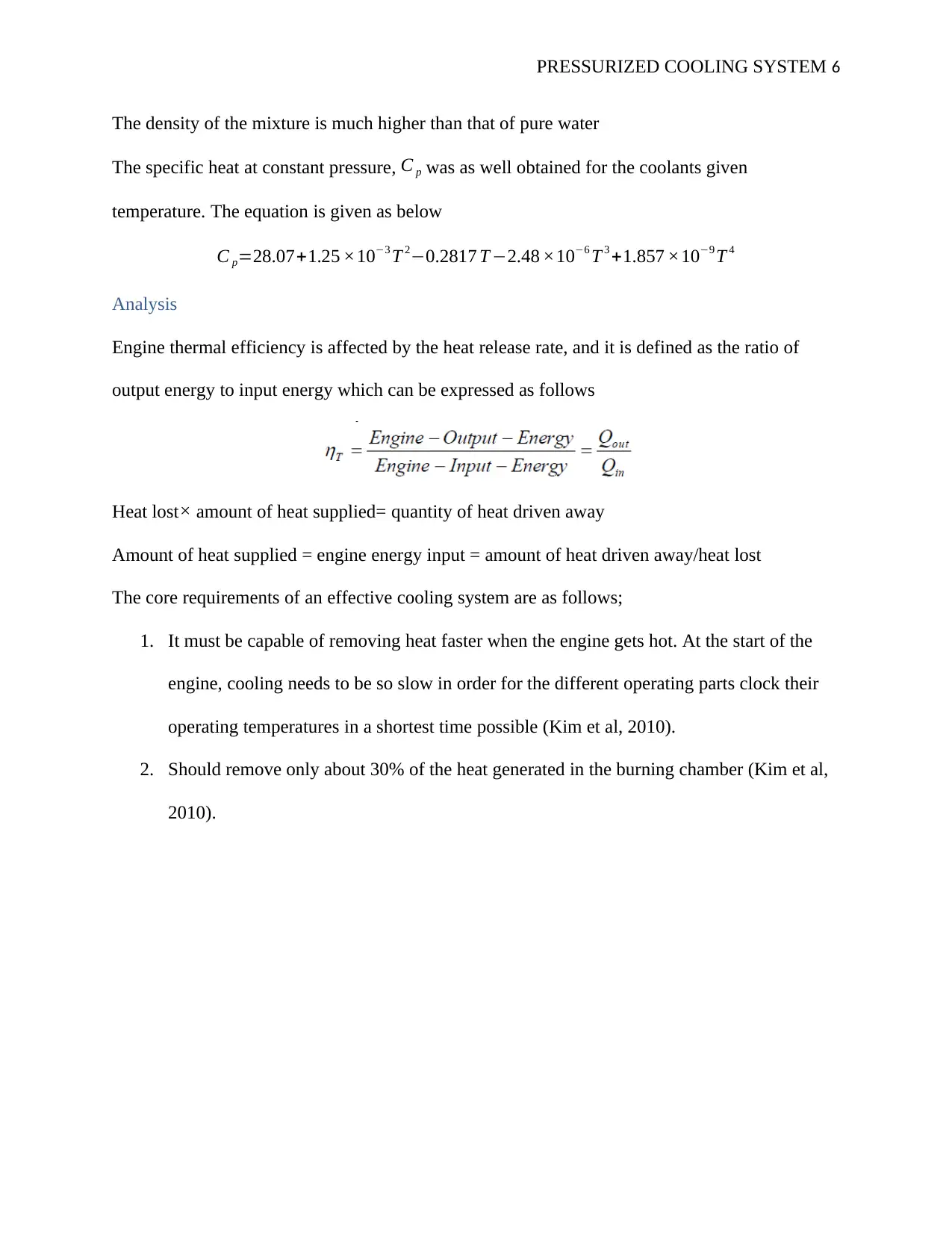
Water density varies as a function of temperature. Such a relation is given below when
temperature (T) is provided.
Polynomial correlation which is simpler is given below;
PRESSURIZED COOLING SYSTEM 6
The density of the mixture is much higher than that of pure water
The specific heat at constant pressure, C p was as well obtained for the coolants given
temperature. The equation is given as below
C p=28.07+1.25 ×10⁻³ T 2−0.2817 T −2.48 ×10⁻⁶ T 3 +1.857 ×10⁻⁹ T 4
Analysis
Engine thermal efficiency is affected by the heat release rate, and it is defined as the ratio of
output energy to input energy which can be expressed as follows
Heat lost× amount of heat supplied= quantity of heat driven away
Amount of heat supplied = engine energy input = amount of heat driven away/heat lost
The core requirements of an effective cooling system are as follows;
1. It must be capable of removing heat faster when the engine gets hot. At the start of the
engine, cooling needs to be so slow in order for the different operating parts clock their
operating temperatures in a shortest time possible (Kim et al, 2010).
2. Should remove only about 30% of the heat generated in the burning chamber (Kim et al,
2010).
⊘ This is a preview!⊘
Do you want full access?
Subscribe today to unlock all pages.

Trusted by 1+ million students worldwide
PRESSURIZED COOLING SYSTEM 7
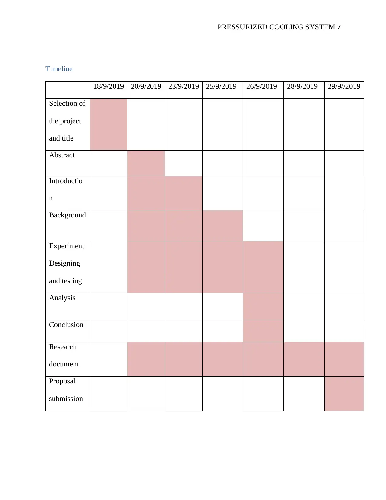
Timeline
18/9/2019 20/9/2019 23/9/2019 25/9/2019 26/9/2019 28/9/2019 29/9//2019
Selection of
the project
and title
Abstract
Introductio
n
Background
Experiment
Designing
and testing
Analysis
Conclusion
Research
document
Proposal
submission
Timeline
18/9/2019 20/9/2019 23/9/2019 25/9/2019 26/9/2019 28/9/2019 29/9//2019
Selection of
the project
and title
Abstract
Introductio
n
Background
Experiment
Designing
and testing
Analysis
Conclusion
Research
document
Proposal
submission
Paraphrase This Document
Need a fresh take? Get an instant paraphrase of this document with our AI Paraphraser
PRESSURIZED COOLING SYSTEM 8
Conclusion
The main aim of this research is to investigate on a suitable pressurized cooling system.
According to the analysis, it accounts for a change in specific heat and density of the engine
coolant resulting from changes in temperature. Comparing pure water against a mixture of water
and ethylene glycol solution, the research shows that a lot of heat is lost in the radiator and
engine while using the pure water as a medium for cooling (Ganesan, 2012). No much change is
seen in energy output and input; thus, we’ve got a small difference in the thermal efficiency.
Nevertheless, with a raised pressure of the cylinder there is a decrease in the heat transfer area
needed. Because improved heat transfer to the atmosphere is reached, the radiator gets hotter,
and it is less expensive to work at a higher pressure to reach the highest temperature
(Scarselletta, 1988) the radiator could work under, taking pure water as a coolant.
Safety issues
While conducting this research, personal safety is so vital as well as the safety of the automobile
under experiment. Engines emit large amounts of heat while under operation, consequently
raising the temperature of the engine to a much higher level which can damage the components
of that engine (Morikawa et al, 1998). This increased temperature can also set the automobile to
a blaze thus causing harm to the operator or any living being around.
PRESSURIZED COOLING SYSTEM 9
References
Ganesan, V. (2012). Internal combustion engines. McGraw Hill Education (India) Pvt Ltd.
Scarselletta, L. (1988). U.S. Patent No. 4,768,484. Washington, DC: U.S. Patent and Trademark
Office.
Van Basshuysen, R., & Schäfer, F. (2004). Internal combustion engine handbook-basics,
components, systems and perspectives (Vol. 345).
Morikawa, T., Inoue, Y., Sugi, H., Aoki, S., & Yamanaka, Y. (1998). U.S. Patent No. 5,730,089.
Washington, DC: U.S. Patent and Trademark Office.
Gopp, A.Y., Sbaschnig, R.W. and Buonocore, R.L., Ford Motor Co, 1996. Method and
apparatus for protecting an engine from overheating. U.S. Patent 5,555,871.
Moroi, T., Ban, T., Hoshino, T. and Mori, H., Toyota Industries Corp, 2000. Coolant circulation
system. U.S. Patent 6,059,198.
Kim, K.B., Choi, K.W., Lee, K.H. and Lee, K.S., 2010. Active coolant control strategies in
automotive e Iwasaki, M., Namai, K., Muramoto, H. and Sumida, M., Calsonic Kansei Corp,
2004. Cooling system for water-cooled internal combustion engine and control method
applicable to cooling system therefor. U.S. Patent 6,739,290.ngines. International Journal of
Automotive Technology, 11(6), pp.767-772.
⊘ This is a preview!⊘
Do you want full access?
Subscribe today to unlock all pages.

Trusted by 1+ million students worldwide
1 out of 9
Related Documents
Your All-in-One AI-Powered Toolkit for Academic Success.
+13062052269
info@desklib.com
Available 24*7 on WhatsApp / Email
![[object Object]](/_next/static/media/star-bottom.7253800d.svg)
Unlock your academic potential
Copyright © 2020–2026 A2Z Services. All Rights Reserved. Developed and managed by ZUCOL.


