Student Assignment: Principles of Comms, Devices & Networks Analysis
VerifiedAdded on 2022/11/27
|19
|3062
|261
Homework Assignment
AI Summary
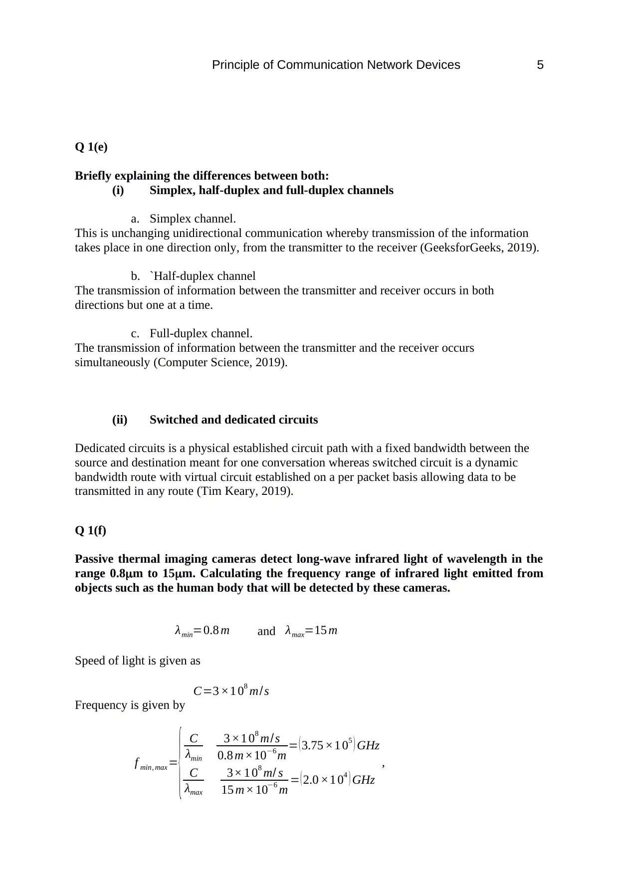
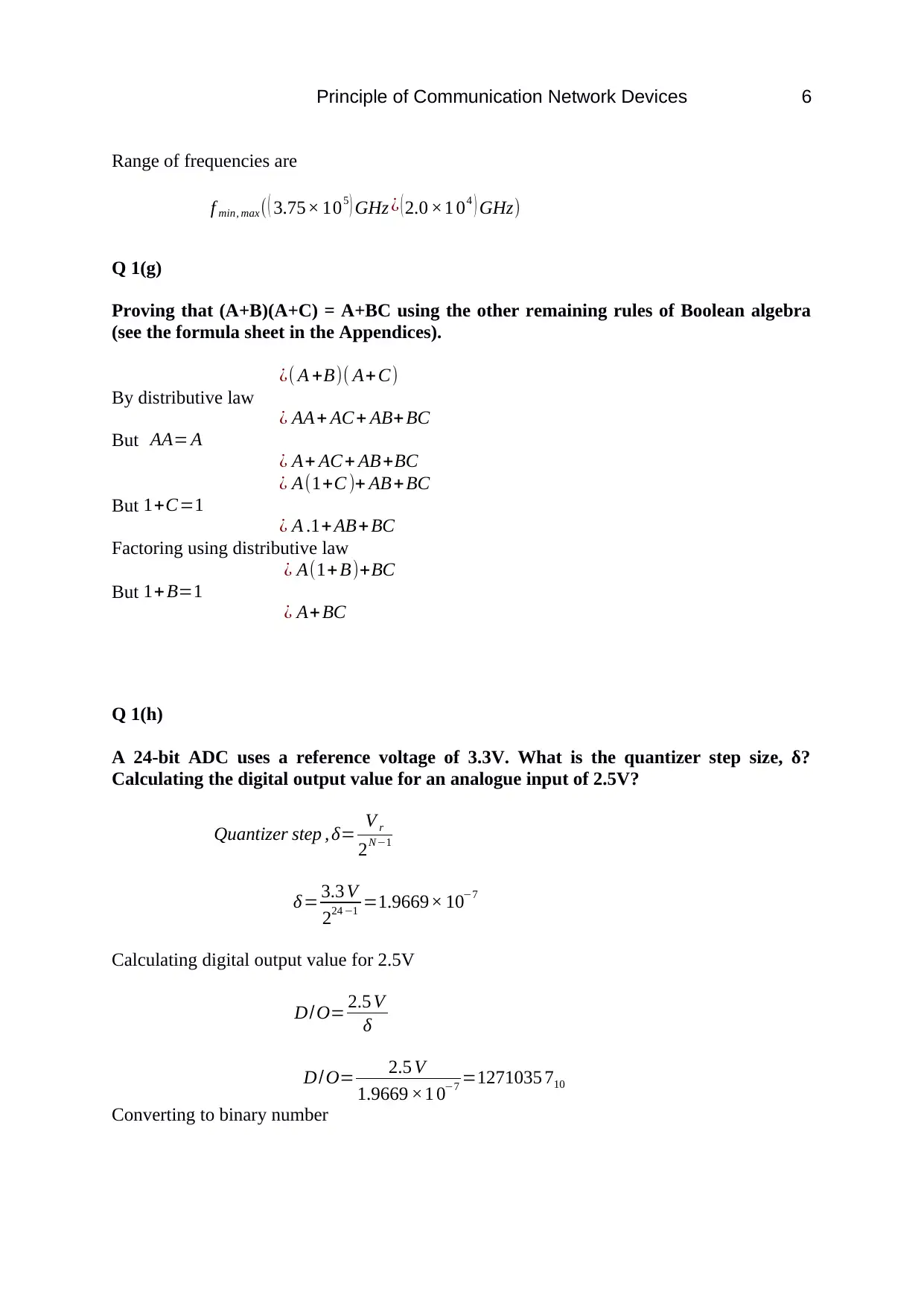
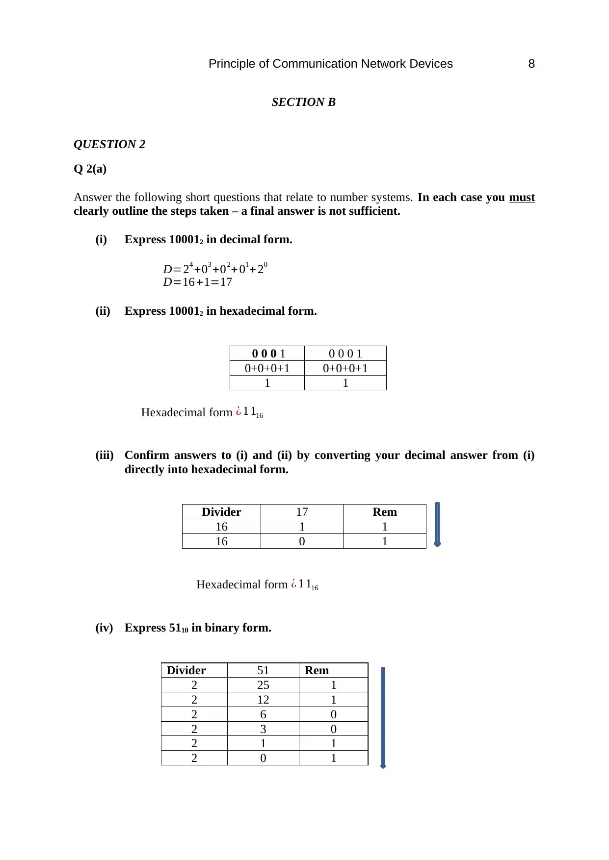
This document presents a comprehensive solution to a Principles of Comms, Devices & Networks assignment. The assignment covers a wide range of topics, including parity bits, EEPROM and RAM memory, IP addresses, routers, subnet masks, and magnetic flux density. It also delves into communication channels (simplex, half-duplex, and full-duplex), thermal imaging, Boolean algebra, ADC quantizer step size, TCP/IP protocols, and mobile network handoffs. Furthermore, the assignment explores number systems (binary, decimal, hexadecimal, and 2's complement), audio sampling rates, parity checks, and cyclic redundancy checks (CRC). It also includes logic circuit design using truth tables, Boolean algebra simplification, De-Morgan's theorem, and the implementation of logic gates (NAND, NOR, and XOR). Finally, the assignment discusses different types of optical fibers and factors affecting signal attenuation.
Contribute Materials
Your contribution can guide someone’s learning journey. Share your
documents today.

Principle of Communication Network Devices 1
Student
Professor
Principle of Communications, Devices and Networks
Date
Student
Professor
Principle of Communications, Devices and Networks
Date
Secure Best Marks with AI Grader
Need help grading? Try our AI Grader for instant feedback on your assignments.

Principle of Communication Network Devices 2
SECTION A
QUESTION 1
Q 1(a)
(i) For the binary number 11111111, indicating the parity bit if odd parity is
employed.
11111111P
Where P is the position of the Parity bit (1) to make it nine 1s.
111111111
(ii) Block Parity is to be applied to the following block of codes. Assuming that even
parity is to be used. Parity bit calculations was completed as shown:
1 1 1 0 1 1 1
1 1 0 0 0 1 1
1 0 0 1 1 1 1
0 0 1 1 1 0 0
0 1 1 1 1 1 0
P(col)
1 1 1 0 1 1 1 0
1 1 0 0 0 1 1 0
1 0 0 1 1 1 1 1
0 0 1 1 1 0 0 1
0 1 1 1 1 1 0 1
P(row
)
1 1 1 1 0 0 1 1

Principle of Communication Network Devices 3
Q 1(b)
(i) Expanding the acronyms and distinguish between the following types of
memory: EEPROM and RAM.
EEPROM :- Electrically Erasable Programmable Read Only Memory
RAM:- Random Access Memory.
Differences between EEPROM and RAM
i. RAM is a read and write memory type while EEPROM is a read only
memory.
ii. Data is lost is erased in RAM memory when powered OFF while in
EEPROM, data is not lost in case of power outage. The memory can only be
erased using higher electrical voltages.
Data in the RAM memory is accessed at a faster rate by the CPU, which is
unlike case in EEPROM memory (Cesar Sanchez, 2019).
(ii) Giving examples where EEPROMs and RAM might be used for in a home PC
and other home devices/appliances.
a) Mobile phones
b) CCTV storage system.
c) Laptops
d) Notebook computers
Q 1(c)
Explaining the following terms: IP address; router; and, subnet mask.
a) IP address
IP (Internet Protocol) address is a 32 bit number that uniquely identifies each computer or
other devices connected on the network for communication. This number is usually expressed
in dotted decimal format (Microsoft Support, 2019).
b) Subnet Mask
Subnet Mask is a 32-bit number used by Transmission Control Protocol (TCP) or IP protocol
to determine whether a host is on the local subnet or on a remote network.
c) Router
A router is a gateway device installed where network meets so as to forward data packet
information between packet-switched computer networks, analysing a given data packet’s
destination IP address, determining the best way for it to reach intended destination and then
forwarding it accordingly (Margaret Rouse, 2019).
.

Principle of Communication Network Devices 4
Q 1(d)
(i) With the aid of a diagram, describing the concept of magnetic flux density.
Magnetic flux density is magnetic flux passing through a unit area perpendicular to the field.
Mathematically, it is the ratio of magnetic flux passing through a plane perpendicular to the
field and the area of the plane as shown below.
B= ∅
A
Where B is the magnetic flux density in Teslas, ∅ is the magnetic flux ∈Weber and A is area
perpendicular to the direction of magnetic flux.
(ii) Two bar magnets of 50mm height and 50mm width at the pole faces are fixed in
position, with their respective N and S poles in close proximity. If the total flux is
0.05 webers, calculating the flux density between the two pole faces. Assuming
that fringing effects are negligible; that is, all of the flux passes between the pole
faces.
B= ∅
A
Where B is the magnetic flux density in Teslas, ∅ is the magnetic flux ∈Weber and A is area
perpendicular to the direction of magnetic flux.
B= 0.05 Webers
( 50 mm ×50 mm ) ×10−6 m2 =20 Teslas
Secure Best Marks with AI Grader
Need help grading? Try our AI Grader for instant feedback on your assignments.

Principle of Communication Network Devices 5
Q 1(e)
Briefly explaining the differences between both:
(i) Simplex, half-duplex and full-duplex channels
a. Simplex channel.
This is unchanging unidirectional communication whereby transmission of the information
takes place in one direction only, from the transmitter to the receiver (GeeksforGeeks, 2019).
b. `Half-duplex channel
The transmission of information between the transmitter and receiver occurs in both
directions but one at a time.
c. Full-duplex channel.
The transmission of information between the transmitter and the receiver occurs
simultaneously (Computer Science, 2019).
(ii) Switched and dedicated circuits
Dedicated circuits is a physical established circuit path with a fixed bandwidth between the
source and destination meant for one conversation whereas switched circuit is a dynamic
bandwidth route with virtual circuit established on a per packet basis allowing data to be
transmitted in any route (Tim Keary, 2019).
Q 1(f)
Passive thermal imaging cameras detect long-wave infrared light of wavelength in the
range 0.8m to 15m. Calculating the frequency range of infrared light emitted from
objects such as the human body that will be detected by these cameras.
λmin=0.8 m and λmax=15 m
Speed of light is given as
C=3 ×1 08 m/ s
Frequency is given by
f min, max =
{ C
λmin
3 ×1 08 m/ s
0.8 m×10−6 m = ( 3.75 ×1 05 ) GHz
C
λmax
3× 1 08 m/ s
15 m× 10−6 m = ( 2.0 ×1 04 ) GHz
,

Principle of Communication Network Devices 6
Range of frequencies are
f min, max( ( 3.75× 10⁵ ) GHz ¿ ( 2.0 ×1 04 ) GHz)
Q 1(g)
Proving that (A+B)(A+C) = A+BC using the other remaining rules of Boolean algebra
(see the formula sheet in the Appendices).
¿( A +B)( A+ C)
By distributive law
¿ AA+ AC+ AB+ BC
But AA= A
¿ A+ AC+ AB+BC
¿ A(1+C )+ AB+BC
But 1+C=1
¿ A .1+ AB+BC
Factoring using distributive law
¿ A(1+ B)+BC
But 1+B=1
¿ A+ BC
Q 1(h)
A 24-bit ADC uses a reference voltage of 3.3V. What is the quantizer step size, δ?
Calculating the digital output value for an analogue input of 2.5V?
Quantizer step , δ= V r
2N−1
δ= 3.3 V
224 −1 =1.9669× 10⁻⁷
Calculating digital output value for 2.5V
D/O= 2.5 V
δ
D/O= 2.5 V
1.9669 ×1 0−7 =1271035 710
Converting to binary number

Principle of Communication Network Devices 7
Q 1(i)
Reasons why have the TCP/IP protocols become so popular by comparison with OSI
protocols.
a) TCP/IP is less complex, more reliable and very cheap alternative for OSI protocols.
Q 1(j)
If a mobile is on a call and is moving through the network, explain what happens if it
moves out of the cell of the initial base-station and into that of another base station.
When making a call, the mobile phone sends and receives radio signals called radio
frequency (RF) fields. The antenna of the nearest base station received the radio signals and
the base station then forwards the signal to an exchange. The exchange connects the call to its
destination, either a fixed line or mobile phone. As the user moves, location update with the
nearest substation is automatically initiated ensures that the mobile phones maintain the link
with the network as users move from one location to another.
[End of Question 1]
[End of Section A]
Paraphrase This Document
Need a fresh take? Get an instant paraphrase of this document with our AI Paraphraser

Principle of Communication Network Devices 8
SECTION B
QUESTION 2
Q 2(a)
Answer the following short questions that relate to number systems. In each case you must
clearly outline the steps taken – a final answer is not sufficient.
(i) Express 100012 in decimal form.
D=24 +03 +02+01+20
D=16 +1=17
(ii) Express 100012 in hexadecimal form.
0 0 0 1 0 0 0 1
0+0+0+1 0+0+0+1
1 1
Hexadecimal form ¿ 1 116
(iii) Confirm answers to (i) and (ii) by converting your decimal answer from (i)
directly into hexadecimal form.
Divider 17 Rem
16 1 1
16 0 1
Hexadecimal form ¿ 1 116
(iv) Express 5110 in binary form.
Divider 51 Rem
2 25 1
2 12 1
2 6 0
2 3 0
2 1 1
2 0 1

Principle of Communication Network Devices 9
Binary¿ 1 10 0 1 12
(v) What is the range of values that can be represented by an 8-bit 2’s
complement form? Do the calculations and determine if it is problematic to
use the 2’s complement form to represent -12810 when we only have 8-bits?
Considering 12810 and converting into 2’s complement
12810=1000 0000
12810=0111 11111' s complement
12810=
0111 1111
+000 0001
1000 0000 }2' s complement
In determining what number could 1000 0000 could represent, 12710 was added as below
+¿
1000 0000
0111 1111
1111 1111
¿ ?
¿ 12710
¿−110
Since 2’s complement of 110=1111 1111 which basically represents −110
Therefore, in 8 bit
1000 0000=−12810
In conclusion the range of values represented by 8-bit 2’s complement is
(−128¿¿ 10¿12710)¿
(Programmedlessons.org, 2019)
Q 2(b)
If we have a high-resolution audio format that aims to provide high quality audio
signals in the frequency range 20Hz to 100kHz with a dynamic range of 100dB.
(i) What minimum sampling rate should be used by this format?
According to Nyquist rate, the minimum sampling frequency should be twice the highest
frequency present in the signal.
f s=2 ×100 kHz=200 kHz
(ii) What is the minimum number of bits required per sample?

Principle of Communication Network Devices 10
Signal to Quantisation noise ratio is given by
SNRdB=6.02 N +1.76
Where N is the number of bits required and SNRdB=100 dB
100 dB=6.02 N +1.76
N= 100−1.76
6.02 =16 bits
(iii) If the only ADC chips that are available are 12-bit, 18-bit, 24-bit and 32-
bit chips, which one should be used (with minimum complexity)?
12-bit is the best because it is faster than the rest and is below 16-bit which is the
minimum number of bits required per sample.
(iv)What is the minimum storage capacity (in Gigabytes) that the disk must have to
store one hour of stereo audio when using your chosen ADC chip?
Sampling frequency ¿( f s)200 kHz , Sample ¿ Sbit ¿=12bit , Time=60 ×60 sec
Finding Audio Storage capacity
Audio Storage = ( f s × Sbit ×t ) × 2
Audio Storage= ( 200000 Hz× 12× 3600 ) × 2=8.64 ×109 bits
Audio Storage= 8.64 ×109 bytes
8 =1.08 ×109 bytes
Audio Storage= 1.08× 10⁹
1024 kB ×1024 MB × 1021Gb Gb=1.0058 GB
Q 2(c)
Describe in detail the differences between “Parity Checks” and “Cyclic Redundancy
Checks.”
Parity checks is an error detecting code mechanism that uses redundant bit called parity bit
which is appended to data block to make number of 1s become even. The parity 1 is added to
block containing odd numbers of 1s to make it even while parity 0 is added on blocks with
even number of 1s.
Secure Best Marks with AI Grader
Need help grading? Try our AI Grader for instant feedback on your assignments.

Principle of Communication Network Devices 11
On contrary, Cyclic Redundancy Checks (CRC) is an error detecting code based on binary
division whereby the sequence of redundant bits (CRC) are appended to the end of data unit
so that the resulting data unit becomes exactly divisible by a second and predetermined
binary number. The remainder shows that the data is altered and has to be rejected
(Nptel.ac.in, 2019).
QUESTION 3
Q 3(a)
A robot has four sensors (A, B, C, D) that illuminate an LED if it is running correctly. A
digital system needs to be designed to illuminate this LED under all of the following
conditions:
- Sensor B is active only when sensors A, C and D are inactive.
- Sensor A is active, regardless of the values of B, C and D.
- Sensor B is inactive when sensors A, C and D are also inactive.
Present a truth table for the system.
For sensor B to be active only when sensors A,C, and D are active
Y 1= A B C D
For sensor A to be active regardless of the values of B, C and D
Y 2=B

Principle of Communication Network Devices 12
For sensor B to be inactive when sensors A, C and D are also inactive
Y 3= AB+ BC+ BD
For the overall output, we OR the outputs
Y = A B C D+ B+ ( AB+BC+ BD )
A B C D Y
0 0 0 0
0 0 0 1
0 0 1 0
0 0 1 1
0 1 0 0
0 1 0 1
0 1 1 0
0 1 1 1
1 0 0 0
1 0 0 1
1 0 1 0
1 0 1 1
1 1 0 0
1 1 0 1
1 1 1 0
1 1 1 1
0
0
0
0
1
1
1
1
0
0
0
0
1
1
1
1

Principle of Communication Network Devices 13
Q 3(b)
Develop a logic expression that describes the system in part (a), and using the rules of
Boolean algebra, minimise the logic expression. Describe the resulting logic circuit.
For the overall output, we OR the outputs
Y = A B C D+ B+ ( AB+ BC+ BD )
Y =B( A C D+ 1+ A +C+D)
But ( A C D+1+ A+C +D )=1
Y =B( 1)
Y =B
Q 3(c)
State De-Morgan’s Theorem and use it to convert the expression and logic circuit from
part (b) to:
(i) A NAND gates only form.
Y =B( A C D+1+ A +C+D)
But according to De-Morgan’s theorem
A C D=A +C+ D
Y =B( A +C+ D+1+ A+ C+D)
But
1+ A+C + D=1
Therefore
Y =B( A +C+ D+1)
Paraphrase This Document
Need a fresh take? Get an instant paraphrase of this document with our AI Paraphraser

Principle of Communication Network Devices 14
(ii) A NOR gates only form.
Y =B( A +C+ D+1)
Assume that only NAND gates/NOR gates with 2 and 3 inputs are available.
Q 3(d)
An Exclusive-OR (X-OR) gate has two inputs.
(i) Draw its symbol.
(ii) A NOR gates only form.
Y =B( A +C+ D+1)
Assume that only NAND gates/NOR gates with 2 and 3 inputs are available.
Q 3(d)
An Exclusive-OR (X-OR) gate has two inputs.
(i) Draw its symbol.

Principle of Communication Network Devices 15
(ii) Draw up its truth table and describe its operation.
X Y XOR
0
0
1
1
0
1
0
1
0
1
1
0
(iii) Write the algebraic expression for the output and demonstrate how it can be
built using any other logic gates.
The output of the XOR gate is as shown below.
XOR= A B+ A B
Using other logic gates (NAND) gates only.
¿ A . ( A . B ) . B ( A . B )
¿ A . ( A . B ) +B . ( A . B )
¿ A . ( A + B ) +B . ( A+B )
¿ ( A+ B ) + ( A+B )
¿ A B+ A B
[End of Question 3]

Principle of Communication Network Devices 16
QUESTION 4
Q 4(a)
Briefly describe three different types of optical fibre, and describe four factors that
result in signal attenuation in optical fibres.
i. Single mode cable
It has a relatively small and narrow glass diameter of 8.3 to 10 microns that allows one
propagation path only. It provides largest transmission bandwidth and less losses of signal
than multimode. It is used for long transmission distance.
ii. Multi-mode cable
It has a relatively larger diameter, 50 to 100 micron, than single mode cable enabling multiple
propagation paths (Arc electronics, 2019).
Factors that results in signal attenuation in optical fibre
(i) Optical absorption
As light travel through the optical fibre, some photons of energy are absorbed by the material
weakening light intensity and degrading the signal.
(ii) Light scattering
It is caused by uneven and rough surface of propagation. This results to light reflection in
random directions thus attenuation of the signal.
(iii) Poor splicing.
When two fibres are misaligned and joined, angular mismatch results to loss of signal as light
is not reflected correctly.
(iv)Bend loss
Fibre bend deviates the core from the axis thus leading to signal loss due to improper
reflection of light (Gui, 2019).
Q 4(b)
(i) Explain the term Fresnel Zone as it applies to point-to-point microwave
transmission. Why is it important to understand the Fresnel zone clearance in
the design of microwave links?
Fresnel zone is a number of concentric ellipsoidal regions of space between and around a
transmitter and receiver. The importance of understanding Fresnel zone is;
Secure Best Marks with AI Grader
Need help grading? Try our AI Grader for instant feedback on your assignments.

Principle of Communication Network Devices 17
(i) Fresnel zone helps to predict whether there are obstructions discontinuities along
the path between the transmitter and receiver such as reflective surfaces which
may cause significant interference.
Fresnel also provides ways of determining the zone where given obstacle causes phase shift
due to reflection (Microwave Link, 2019).
(ii) Two 25GHz microwave radio systems antennas are spaced 10 kilometres apart.
Both the transmitter and receiver antennas are 250 metres above the ground. It
is proposed to put a highly reflective building at the exact midpoint between the
two antennas. What is the maximum possible height of the building if the first
Fresnel zone clearance requirement is to be met? Note: Assume that the speed of
light = 3 × 10⁸ m/s.
Fresnel’s zone radius is given by;
rm =8.657 √ D
f + H
Where rm is Fresne l' s radius∈meters, D is the distance between antennas in km, H is the
height of the antenna in meter and f is the frequency in GHz
rm =8.657 √ 10 km
25 GHz +250 m=255.75m
The maximum height of the building is (255.75 m)
Q 4(c)
Outline the specifications of and the services supported by 3rd Generation Wireless
Systems.
Specifications of 3rd Generation wireless are five which can be described as;
(i) It has three standards that are based on CDMA which include TD-SCDMA, and
FDMA/TDMA.
(ii) Two standards that are based on TDMA, i.e FDMA/TDMA and TDMA-SC
(EDGE).
Services supported by 3rd generation are;
(i) Broadband multimedia for instance video conferencing.
(ii) Instant messaging email and messaging with add-on of multimedia

Principle of Communication Network Devices 18
REFERENCES.
Microsoft Support. (2019). Understanding TCP/IP addressing and subnetting basics. [online]
Available at: https://support.microsoft.com/en-us/help/164015/understanding-tcp-ip-
addressing-and-subnetting-basics [Accessed 9 Jul. 2019].
Cesar Sanchez, (2019). Explain the differences between a RAM, ROM, EEPROM, and
DRAM. [online] Available at: https://www.coursehero.com/file/p42blfq/Explain-the-
differences-between-a-RAM-ROM-EEPROM-and-DRAM-RAM-Random-Access/
[Accessed 9 Jul. 2019].
Margaret Rouse. (2019). Routers - Definition from WhatIs.com. [online] Available at:
https://searchnetworking.techtarget.com/definition/router [Accessed 9 Jul. 2019].
GeeksforGeeks. (2019). Transmission Modes in Computer Networks (Simplex, Half-Duplex
and Full-Duplex) - GeeksforGeeks. [online] Available at:
https://www.geeksforgeeks.org/transmission-modes-computer-networks/ [Accessed 9 Jul.
2019].
Computer Science. (2019). Simplex, Half Duplex, Full Duplex | Definition, Comparison &
Information. [online] Teach Computer Science. Available at:
https://teachcomputerscience.com/simplex-half-duplex-full-duplex/ [Accessed 9 Jul. 2019].
Tim Keary. (2019). Circuit Switching vs Packet Switching: What are the differences?.
[online] Available at: https://www.comparitech.com/net-admin/circuit-switching-vs-packet-
switching/ [Accessed 9 Jul. 2019].
Programmedlessons.org. (2019). Range of Integers with 2's Complement. [online] Available
at: http://programmedlessons.org/AssemblyTutorial/Chapter-08/ass08_20.html [Accessed 9
Jul. 2019].
Nptel.ac.in. (2019). [online] Available at:
https://nptel.ac.in/courses/106105080/pdf/M3L2.pdf [Accessed 10 Jul. 2019].
Arc electronics. (2019). Fiber Optic Cable single-mode multi-mode Tutorial. [online]
Available at: https://www.arcelect.com/fibercable.htm [Accessed 10 Jul. 2019].

Principle of Communication Network Devices 19
Gui, A. (2019). Understanding Losses in optical fiber. [online] Tutorials Of Fiber Optic
Products. Available at: http://www.fiber-optic-tutorial.com/understanding-losses-fiber-
optic.html [Accessed 10 Jul. 2019].
Microwave Link. (2019). Fresnel Zone - Microwave Planning - Microwave Link. [online]
Available at: https://www.microwave-link.com/microwave/fresnel-zone-microwave-
planning/ [Accessed 10 Jul. 2019].
1 out of 19
Related Documents

Your All-in-One AI-Powered Toolkit for Academic Success.
+13062052269
info@desklib.com
Available 24*7 on WhatsApp / Email
Unlock your academic potential
© 2024 | Zucol Services PVT LTD | All rights reserved.