AUEC2-005: Producing Components Hand Fitting Techniques Assessment
VerifiedAdded on 2020/12/15
|23
|6431
|7762
Homework Assignment
AI Summary
This document presents a comprehensive assessment of hand fitting techniques, encompassing essential knowledge and understanding required for the production of components. The assignment covers a wide range of topics, starting with health and safety protocols, including the importance of personal protective equipment (PPE), risk assessments, and safe working practices. It emphasizes the significance of maintaining a safe and tidy work area to minimize hazards. The assessment further delves into the hazards associated with hand fitting activities, such as the use of power tools and trailing leads, and how to mitigate them. It also addresses workplace behaviors and the implications of non-adherence. The assignment includes procedures for obtaining drawings and job instructions, interpreting engineering drawings, understanding first and third angle projections, imperial and metric systems, and the importance of datum points and tolerances. The document explains the conversion between metric and imperial measurements, and covers material preparation, including defect checks and applying marking out mediums. Finally, the document discusses methods of holding and supporting workpieces during marking out activities, and the use of marking out conventions.
| AUEC2-005 Tyler Dow
Producing components using hand fitting techniques
Knowledge assessed and evidenced feedback
Assessor comments Learner comments
Assessor
Signature
Learner
Signature Date
Producing components using hand fitting techniques
Knowledge assessed and evidenced feedback
Assessor comments Learner comments
Assessor
Signature
Learner
Signature Date
Paraphrase This Document
Need a fresh take? Get an instant paraphrase of this document with our AI Paraphraser

| AUEC2-005
THIS PAGE IS INTENTIONALLY BLANK
THIS PAGE IS INTENTIONALLY BLANK
| AUEC2-005
Producing components using hand fitting techniques
Knowledge and Understanding
The apprentice must know and understand:
K1 Describe the health and safety requirements and safe working practices and
procedures required for the hand fitting activities undertaken.
- When performing any hand fitting job, the correct PPE and training is required to
perform the specific job.
- Employers have a duty to provide personal protective equipment (PPE) for their
employees within the workplace. PPE is defined as equipment that will protect the
user at work against health or safety hazards at work.
- The user must wear their PPE at all times during work to minimise risk and injury
to themselves and others. It can include items such as gloves, eye protection,
steel-toe boots and high-visibility clothing.
- Risk assessments are often carried out by an external company/governing body to
ensure the employer knows when and where to enforce PPE. For an employer to
implement measures to control substances hazardous to health and other items
that can cause injury, they must complete a risk assessment to understand what is
required.
- It is important for employers to have information/training available to the
employees so that they understand the hazards involved. 1st aid kits, anti-bacterial
wipes and running water should always be available in a workshop area to ensure
the safety of workers.
- Only when the worker is competent and confident in completing the job, should
they begin the task given. If unsure, they should ask for further training.
- A risk assessment must be completed on the task being undertaken which will
detail all the hazards involving machinery, tools and space.
- COSHH must be considered if dealing with substances which can cause damage;
for example, if some metal work is to be cleaned and the cleaning fluid has an
irritant sign on it, then the worker must use gloves.
- The health and safety at work act of 1974 states that employers have a duty of
care and must ensure all areas of the workplace are safe for employees to use at
all times.
- Equipment such as machinery and tools must be regularly maintained to enforce
a safe working environment so as to not cause harm to the employees’ health.
⊘ This is a preview!⊘
Do you want full access?
Subscribe today to unlock all pages.
Trusted by 1+ million students worldwide
| AUEC2-005
K2 Explain the importance of wearing appropriate protective clothing and equipment
(PPE), and of keeping the work area safe and tidy.
- Wearing the correct P.P.E is extremely important; this will protect the person
from getting trapped or hurt in any way.
- Examples of this include wearing overalls and safety glasses to protect the skin
from swarf off the material.
- Safety boots with steel toe caps ensure that the feet are protected from any
potential falling objects.
- Sweeping the work area safe and tidy is also extremely important; this will
eliminate any hazards to all personnel in and around the area.
- The swarf can easily pierce the skin, so the sides must be wiped clean and all
swarf is to be removed to eliminate the risk of someone leaning on it or touching it
where they would risk hurting themselves.
K3
State the hazards associated with the hand fitting activities (such as use of power
tools, trailing leads or hoses, damaged or badly maintained tools and equipment,
using files with damaged or poor fitting handles), and how they can be minimised.
- The hazards involving hand fitting activities include the use of power tools which
must only be used by a competent and confident worker. Someone who has no
knowledge on how to use the tool will put themselves and others at risk of injury.
- Trailing leads are trip hazards which can cause serious injury as someone could
fall over and hurt themselves as they may not see the lead. This hazard can be
minimised by putting the wire out of the way or using mats which allow the wire to
safely run below them.
- This incident will also happen when hoses are left lying around the work shop; they
must be placed in a safe area, away from the main workplace.
- Damaged or badly maintained tools and equipment can cause damage to not only
the person using it but other people surrounding. For example, if a hammer head
has become loose to the handle, it runs the risk of coming off the handle and
potentially hitting other people. To minimise this risk, tools and equipment must be
checked before use.
Paraphrase This Document
Need a fresh take? Get an instant paraphrase of this document with our AI Paraphraser
| AUEC2-005
K4
Explain the importance of applying the appropriate behaviours in the workplace
and the implications for both the apprentice and the business if these are not
adhered to
- Improper work ethic can lead to accidents and a loss of efficiency in work. It is
important people are professional in the workplace to ensure work is complete and
safety is ensured; failure to do this increases the likelihood of accidents as health
and safety where the user is not being put into practice. This could lead to injury,
lost working time and production could be affected.
K5 Outline the procedure for obtaining the required drawings, job instructions and
other related specifications
- All documentation for the job is located in the worker’s training or assessment
folder. If any further job instructions are required they will be provided by the
trainer in charge or competent overseeing personnel.
- Specifications can be found in the engineer’s data reference book such as drill
sizes and conversions.
| AUEC2-005
K6
Explain how to use and extract information from engineering drawings and related
specifications (to include symbols and conventions to appropriate BS or ISO
standards), in relation to work undertaken
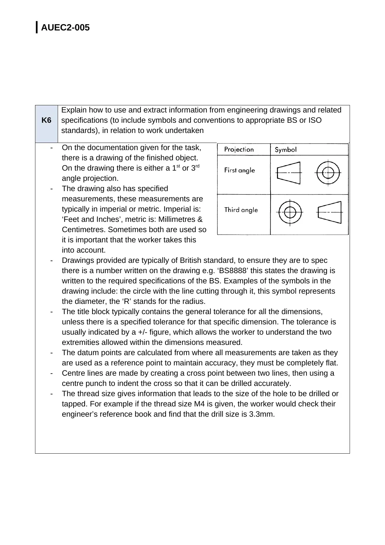
- On the documentation given for the task,
there is a drawing of the finished object.
On the drawing there is either a 1st or 3rd
angle projection.
- The drawing also has specified
measurements, these measurements are
typically in imperial or metric. Imperial is:
‘Feet and Inches’, metric is: Millimetres &
Centimetres. Sometimes both are used so
it is important that the worker takes this
into account.
- Drawings provided are typically of British standard, to ensure they are to spec
there is a number written on the drawing e.g. ‘BS8888’ this states the drawing is
written to the required specifications of the BS. Examples of the symbols in the
drawing include: the circle with the line cutting through it, this symbol represents
the diameter, the ‘R’ stands for the radius.
- The title block typically contains the general tolerance for all the dimensions,
unless there is a specified tolerance for that specific dimension. The tolerance is
usually indicated by a +/- figure, which allows the worker to understand the two
extremities allowed within the dimensions measured.
- The datum points are calculated from where all measurements are taken as they
are used as a reference point to maintain accuracy, they must be completely flat.
- Centre lines are made by creating a cross point between two lines, then using a
centre punch to indent the cross so that it can be drilled accurately.
- The thread size gives information that leads to the size of the hole to be drilled or
tapped. For example if the thread size M4 is given, the worker would check their
engineer’s reference book and find that the drill size is 3.3mm.
K6
Explain how to use and extract information from engineering drawings and related
specifications (to include symbols and conventions to appropriate BS or ISO
standards), in relation to work undertaken
- On the documentation given for the task,
there is a drawing of the finished object.
On the drawing there is either a 1st or 3rd
angle projection.
- The drawing also has specified
measurements, these measurements are
typically in imperial or metric. Imperial is:
‘Feet and Inches’, metric is: Millimetres &
Centimetres. Sometimes both are used so
it is important that the worker takes this
into account.
- Drawings provided are typically of British standard, to ensure they are to spec
there is a number written on the drawing e.g. ‘BS8888’ this states the drawing is
written to the required specifications of the BS. Examples of the symbols in the
drawing include: the circle with the line cutting through it, this symbol represents
the diameter, the ‘R’ stands for the radius.
- The title block typically contains the general tolerance for all the dimensions,
unless there is a specified tolerance for that specific dimension. The tolerance is
usually indicated by a +/- figure, which allows the worker to understand the two
extremities allowed within the dimensions measured.
- The datum points are calculated from where all measurements are taken as they
are used as a reference point to maintain accuracy, they must be completely flat.
- Centre lines are made by creating a cross point between two lines, then using a
centre punch to indent the cross so that it can be drilled accurately.
- The thread size gives information that leads to the size of the hole to be drilled or
tapped. For example if the thread size M4 is given, the worker would check their
engineer’s reference book and find that the drill size is 3.3mm.
⊘ This is a preview!⊘
Do you want full access?
Subscribe today to unlock all pages.
Trusted by 1+ million students worldwide
| AUEC2-005
K7 Explain how to interpret first and third angle drawings, imperial and metric systems
of measurement, workpiece reference points and system of tolerancing.
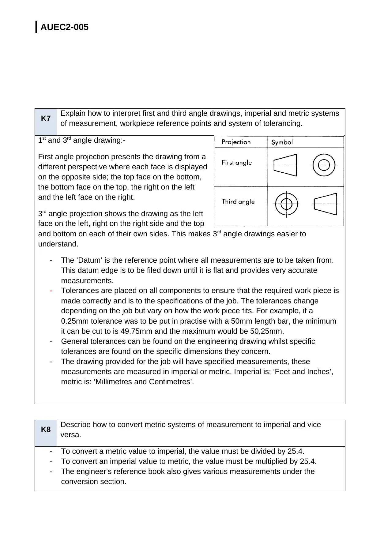
1st and 3rd angle drawing:-
First angle projection presents the drawing from a
different perspective where each face is displayed
on the opposite side; the top face on the bottom,
the bottom face on the top, the right on the left
and the left face on the right.
3rd angle projection shows the drawing as the left
face on the left, right on the right side and the top
and bottom on each of their own sides. This makes 3rd angle drawings easier to
understand.
- The ‘Datum’ is the reference point where all measurements are to be taken from.
This datum edge is to be filed down until it is flat and provides very accurate
measurements.
- Tolerances are placed on all components to ensure that the required work piece is
made correctly and is to the specifications of the job. The tolerances change
depending on the job but vary on how the work piece fits. For example, if a
0.25mm tolerance was to be put in practise with a 50mm length bar, the minimum
it can be cut to is 49.75mm and the maximum would be 50.25mm.
- General tolerances can be found on the engineering drawing whilst specific
tolerances are found on the specific dimensions they concern.
- The drawing provided for the job will have specified measurements, these
measurements are measured in imperial or metric. Imperial is: ‘Feet and Inches’,
metric is: ‘Millimetres and Centimetres’.
K8 Describe how to convert metric systems of measurement to imperial and vice
versa.
- To convert a metric value to imperial, the value must be divided by 25.4.
- To convert an imperial value to metric, the value must be multiplied by 25.4.
- The engineer’s reference book also gives various measurements under the
conversion section.
K7 Explain how to interpret first and third angle drawings, imperial and metric systems
of measurement, workpiece reference points and system of tolerancing.
1st and 3rd angle drawing:-
First angle projection presents the drawing from a
different perspective where each face is displayed
on the opposite side; the top face on the bottom,
the bottom face on the top, the right on the left
and the left face on the right.
3rd angle projection shows the drawing as the left
face on the left, right on the right side and the top
and bottom on each of their own sides. This makes 3rd angle drawings easier to
understand.
- The ‘Datum’ is the reference point where all measurements are to be taken from.
This datum edge is to be filed down until it is flat and provides very accurate
measurements.
- Tolerances are placed on all components to ensure that the required work piece is
made correctly and is to the specifications of the job. The tolerances change
depending on the job but vary on how the work piece fits. For example, if a
0.25mm tolerance was to be put in practise with a 50mm length bar, the minimum
it can be cut to is 49.75mm and the maximum would be 50.25mm.
- General tolerances can be found on the engineering drawing whilst specific
tolerances are found on the specific dimensions they concern.
- The drawing provided for the job will have specified measurements, these
measurements are measured in imperial or metric. Imperial is: ‘Feet and Inches’,
metric is: ‘Millimetres and Centimetres’.
K8 Describe how to convert metric systems of measurement to imperial and vice
versa.
- To convert a metric value to imperial, the value must be divided by 25.4.
- To convert an imperial value to metric, the value must be multiplied by 25.4.
- The engineer’s reference book also gives various measurements under the
conversion section.
Paraphrase This Document
Need a fresh take? Get an instant paraphrase of this document with our AI Paraphraser
| AUEC2-005
K9
Explain how to prepare the materials in readiness for the marking out activities, in
order to enhance clarity, accuracy and safety (such as visually checking for
defects, cleaning the materials, removing burrs and sharp edges, applying a
marking out medium)
- When the material has been collected for the job, the material should be measured
to ensure that it is fit for purpose and the person performing the job can make the
piece using that size material.
- Another check includes visually inspecting the material for any burrs or defects,
this can include deep scratches or dents in the material; dents and scratches will
affect the final product. If there are any burrs on the material they can easily be
removed using a file.
- Once all checks are complete and the material has no defects the material is to
have a small layer of marking blue applied to it, this dye will allow the worker to
mark out the measurements on the material accurately.
K10
Explain how to select and establish a suitable datum; the importance of ensuring
that marking out is undertaken from the selected datum, and the possible effects of
working from a different datum.
| AUEC2-005
- The datum edge needs to be a flat edge of the material, this edge will need to be
filed down and measured against a 90 degrees engineer’s square to ensure that
the edge is completely flat and has no uneven edges or bumps. From this edge all
measurements can then be taken, these measurements will be extremely accurate
due to the flat surface.
- If measurements were made using any other surface edge then they will be
inaccurate and the worker runs the risk of not reaching the specifications of the job
aligned.
K11
State the methods of holding and supporting the workpiece during the marking out
activities, and equipment that can be used (such as surface plates, angle plates,
vee blocks and clamps, parallel bars, screw jacks)
When marking out dimensions on the work piece, the worker must ensure it is held in
place and does not move. This is to avoid any errors in marking out the dimensions; the
datum edge is placed flat along the surface to ensure the work is kept completely flat
whilst being marked. This will keep the work stable and accurate when being marked out
via scribing or a height gauge.
To ensure the workpiece is flat and square, an engineer’s square is used to check for
inconsistencies in the datum so it can be corrected before continuing the workpiece.
Angle plates are used for supporting work vertically for marking out.A v-block is used to
ensure circular work-piecesareheld securely by clamping them down in place. It can also
be used when machining the work-piece so there are no inconsistencies in the work.
⊘ This is a preview!⊘
Do you want full access?
Subscribe today to unlock all pages.
Trusted by 1+ million students worldwide
| AUEC2-005
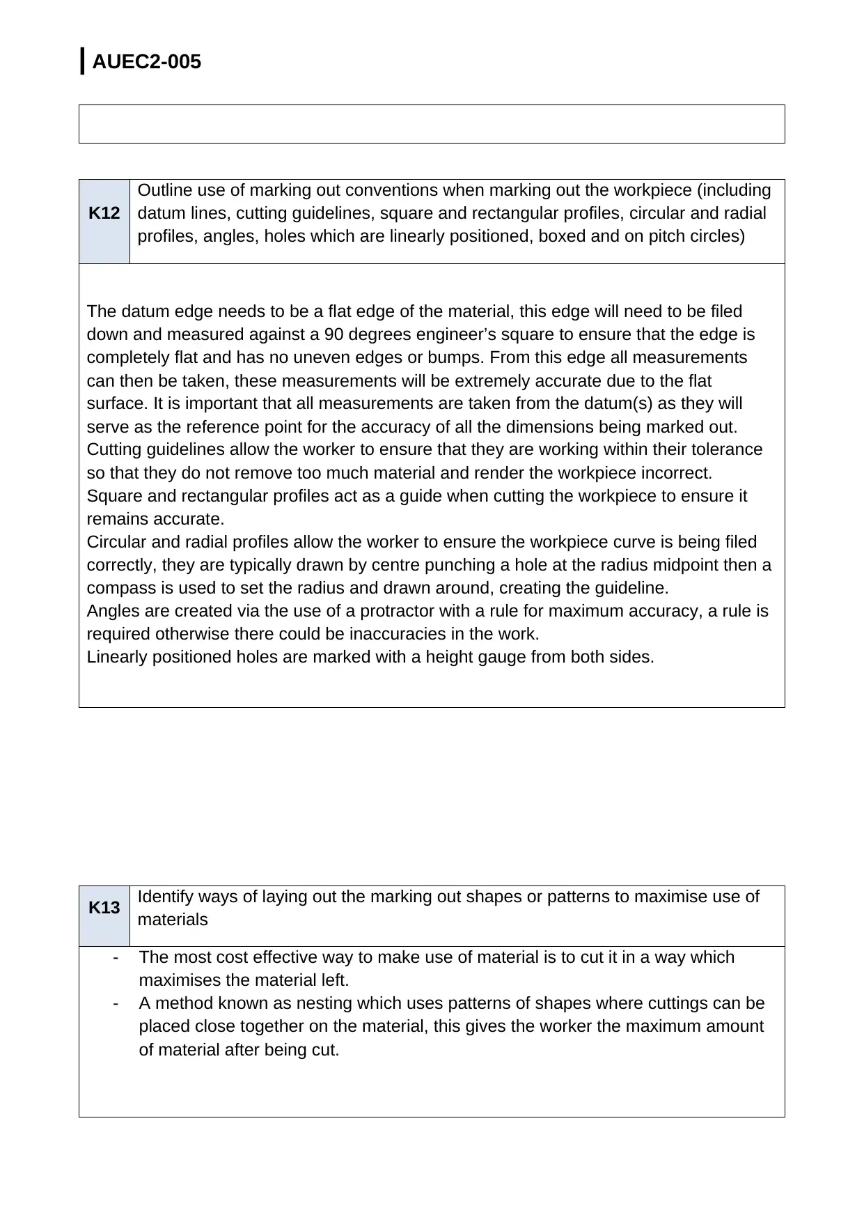
K12
Outline use of marking out conventions when marking out the workpiece (including
datum lines, cutting guidelines, square and rectangular profiles, circular and radial
profiles, angles, holes which are linearly positioned, boxed and on pitch circles)
The datum edge needs to be a flat edge of the material, this edge will need to be filed
down and measured against a 90 degrees engineer’s square to ensure that the edge is
completely flat and has no uneven edges or bumps. From this edge all measurements
can then be taken, these measurements will be extremely accurate due to the flat
surface. It is important that all measurements are taken from the datum(s) as they will
serve as the reference point for the accuracy of all the dimensions being marked out.
Cutting guidelines allow the worker to ensure that they are working within their tolerance
so that they do not remove too much material and render the workpiece incorrect.
Square and rectangular profiles act as a guide when cutting the workpiece to ensure it
remains accurate.
Circular and radial profiles allow the worker to ensure the workpiece curve is being filed
correctly, they are typically drawn by centre punching a hole at the radius midpoint then a
compass is used to set the radius and drawn around, creating the guideline.
Angles are created via the use of a protractor with a rule for maximum accuracy, a rule is
required otherwise there could be inaccuracies in the work.
Linearly positioned holes are marked with a height gauge from both sides.
K13 Identify ways of laying out the marking out shapes or patterns to maximise use of
materials
- The most cost effective way to make use of material is to cut it in a way which
maximises the material left.
- A method known as nesting which uses patterns of shapes where cuttings can be
placed close together on the material, this gives the worker the maximum amount
of material after being cut.
Paraphrase This Document
Need a fresh take? Get an instant paraphrase of this document with our AI Paraphraser
| AUEC2-005
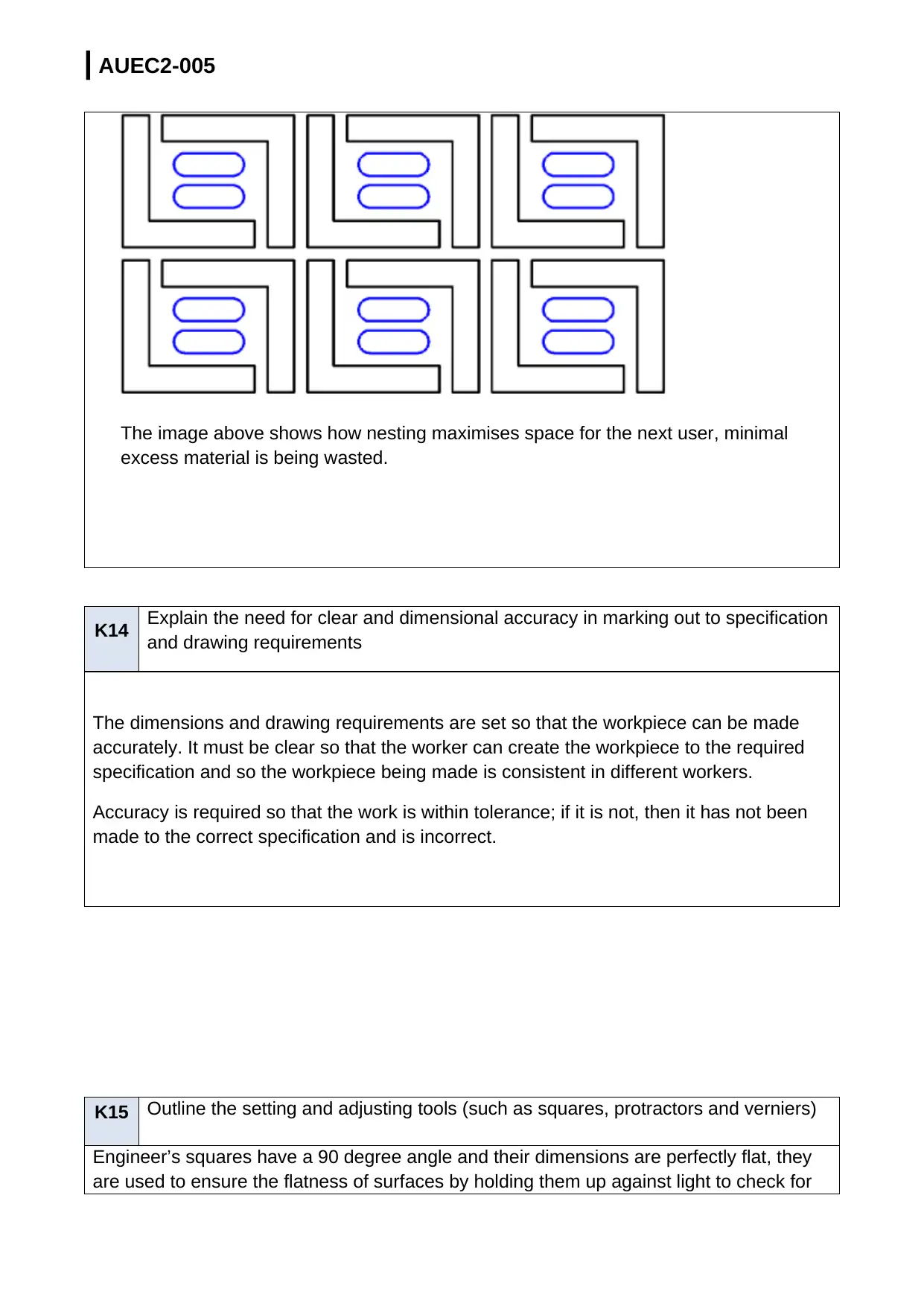
The image above shows how nesting maximises space for the next user, minimal
excess material is being wasted.
K14 Explain the need for clear and dimensional accuracy in marking out to specification
and drawing requirements
The dimensions and drawing requirements are set so that the workpiece can be made
accurately. It must be clear so that the worker can create the workpiece to the required
specification and so the workpiece being made is consistent in different workers.
Accuracy is required so that the work is within tolerance; if it is not, then it has not been
made to the correct specification and is incorrect.
K15 Outline the setting and adjusting tools (such as squares, protractors and verniers)
Engineer’s squares have a 90 degree angle and their dimensions are perfectly flat, they
are used to ensure the flatness of surfaces by holding them up against light to check for
| AUEC2-005
gaps. The worker can see how their work-piece requires adjusting from where the gaps of
light pass through. The worker must ensure the surface they lean on is flat or their work-
piece may contain inconsistencies. To ensure the engineer’s square is correct, the worker
can put it up against a bottle jack and use a feeler gauge to check for gaps. Or they can
put the square against a flat plate, scribe across the plate then turn it over and scribe
again, if the lines do not match up the square is incorrect.
Protractors measure angles precisely, there is typically a rule in the middle with a bolt
which is manually tightened when the desired angle is selected. The worker must find the
side of the rule that lines up correctly with their work then measure.
Vernier calipersmust be set to zero before use or the work-piece may be incorrect. The
worker must adjust the slider with the work-piece in place, tighten the bolt to ensure it
doesn’t move out of place then take their measurement.
K16
Explain the importance of using tools only for the purpose intended; the care that is
required when using the equipment and tools; the proper way of storing tools and
equipment between operations
- Every tool is made to perform a specific job; for example a file is made to file down
a material to a certain size or to smooth a surface, it must not be used for any
other purpose as it could lead to the tool becoming hazardous to the worker.
- If the worker chose to use the file as a hammer then there is the risk of the file
head coming out of the handle socket or chipping. The handle on a file is not as
secure as one that would be on a hammer, if it was to come out of the handle, the
worker runs the risk of the piece of equipment flying off and hurting someone or
damaging machinery.
- When finished with the tool it should be checked over to ensure that there is no
damage to it and it is safe for the next person to use. It will then be safely stored in
a safe place that is away from people and inaccessible to unauthorised personnel
such as a locked cupboard.
⊘ This is a preview!⊘
Do you want full access?
Subscribe today to unlock all pages.
Trusted by 1+ million students worldwide
1 out of 23
Related Documents


Your All-in-One AI-Powered Toolkit for Academic Success.
+13062052269
info@desklib.com
Available 24*7 on WhatsApp / Email
![[object Object]](/_next/static/media/star-bottom.7253800d.svg)
Unlock your academic potential
Copyright © 2020–2026 A2Z Services. All Rights Reserved. Developed and managed by ZUCOL.