Anglia Ruskin University: 3-Wheeler Cart Design and Manufacture Report

Verified

Added on  2023/06/10

|41
|4747
|247
Report
AI Summary
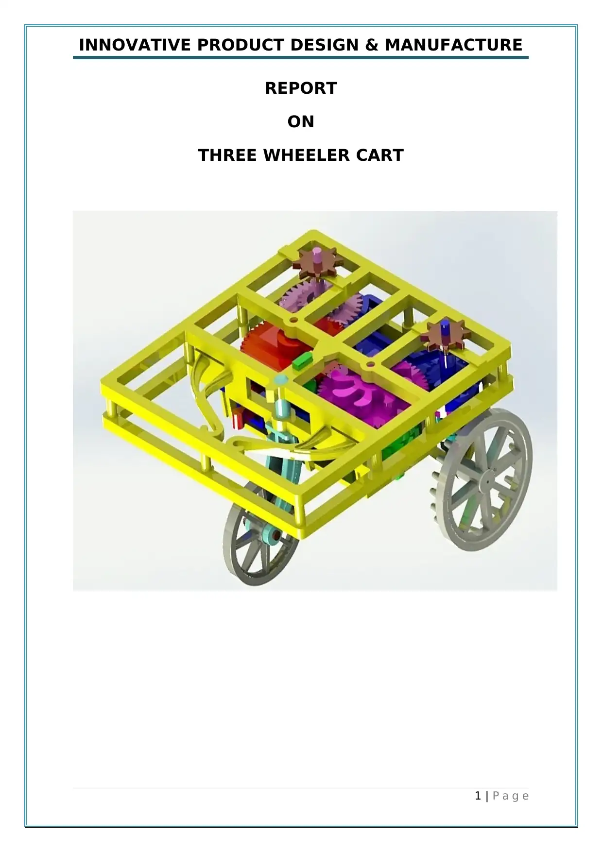
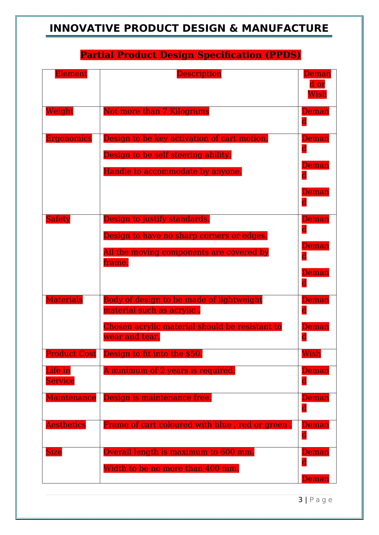
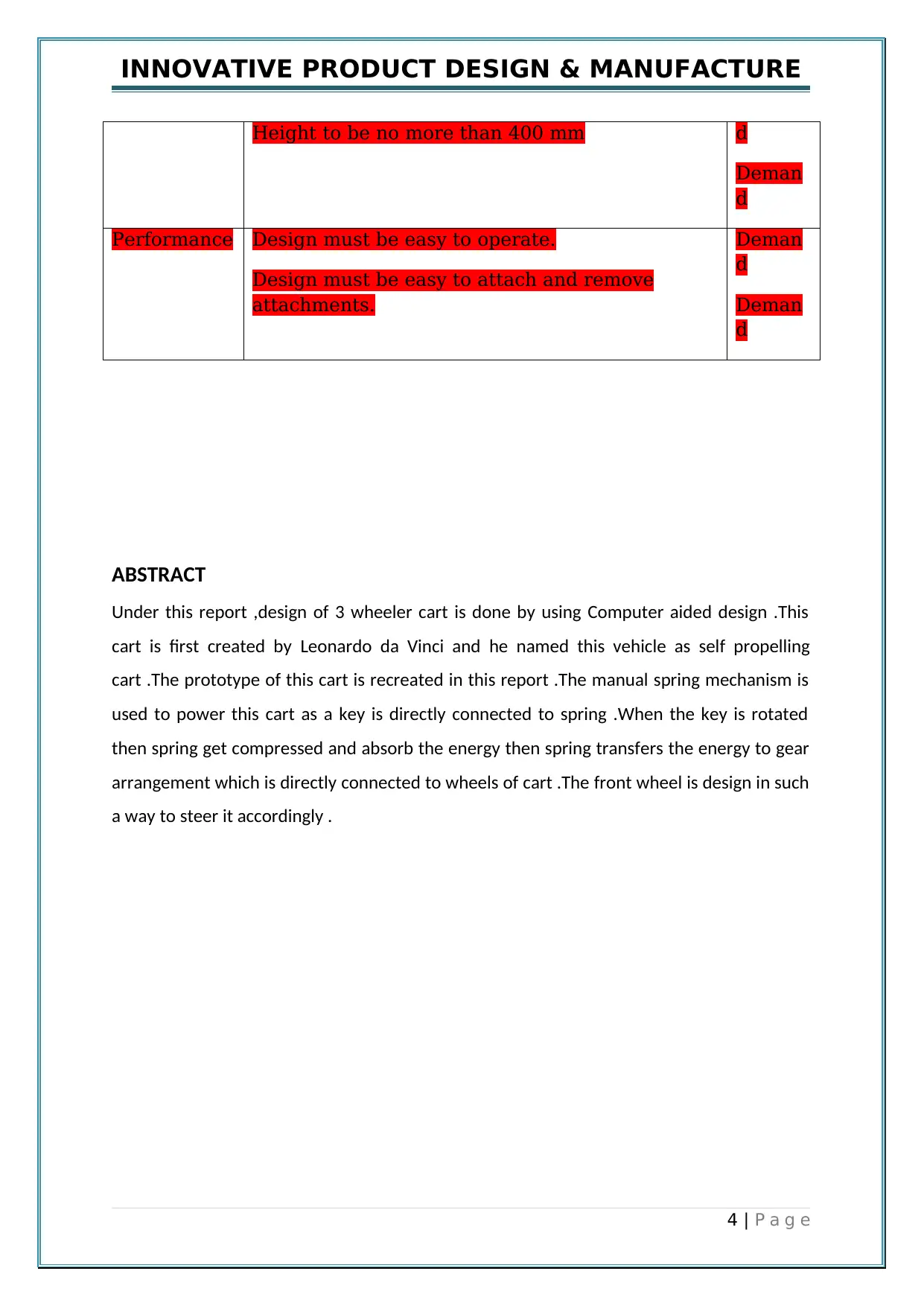
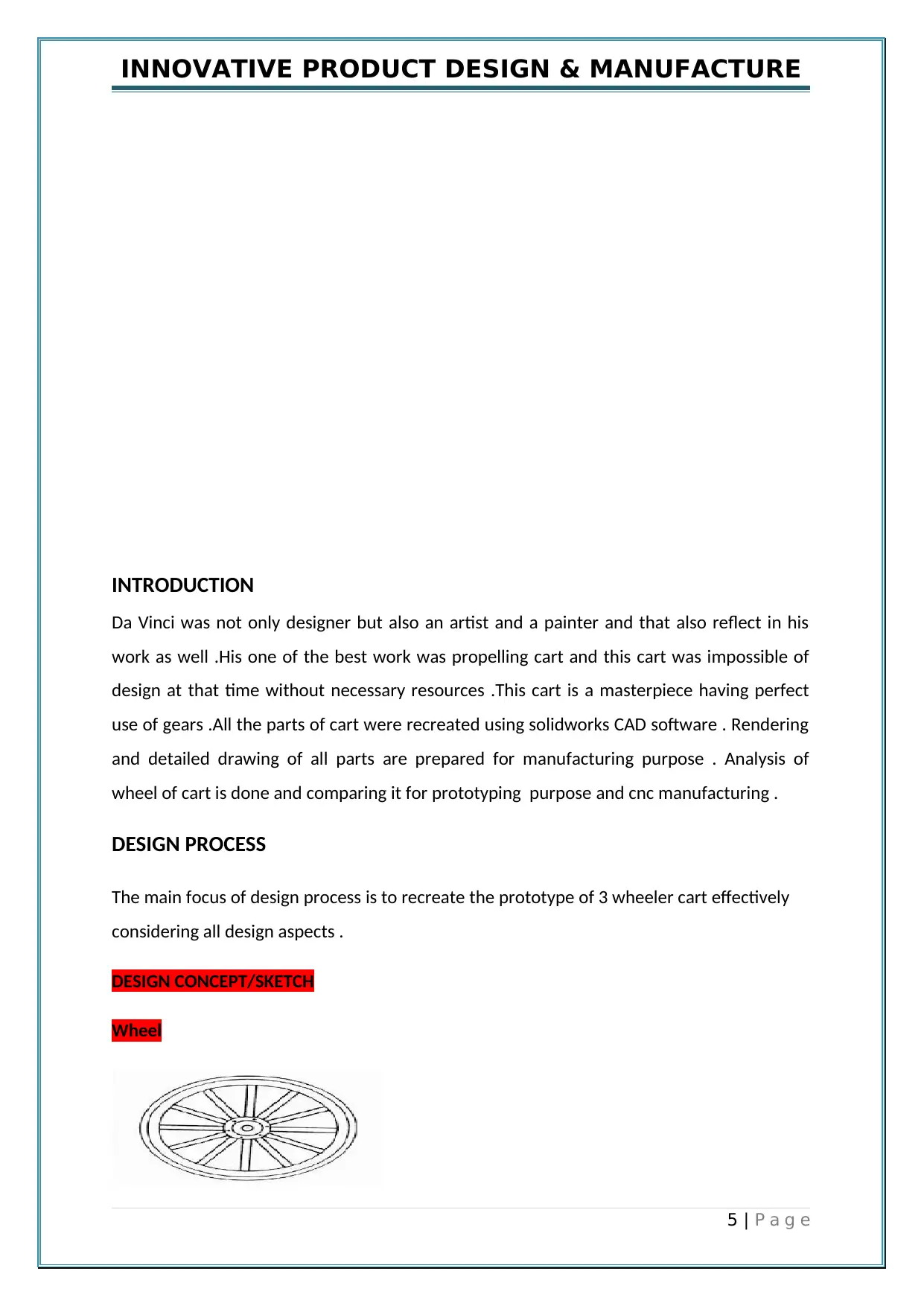
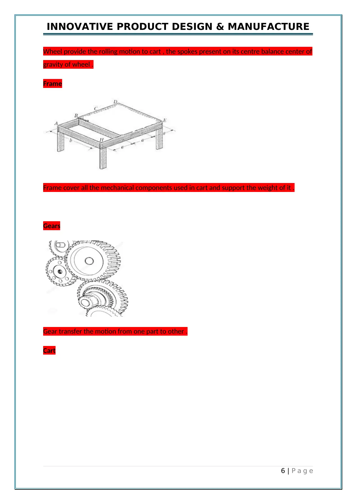
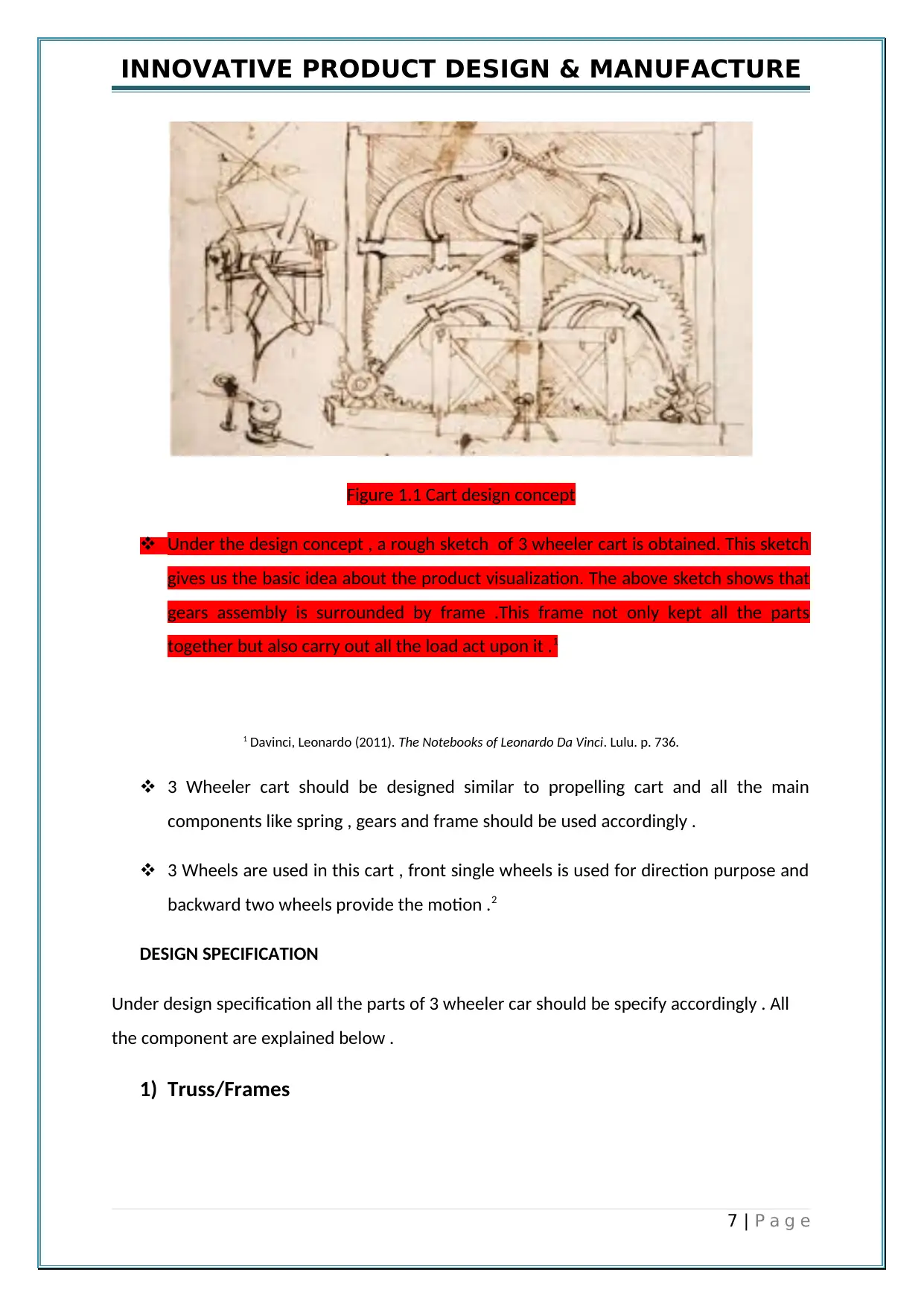
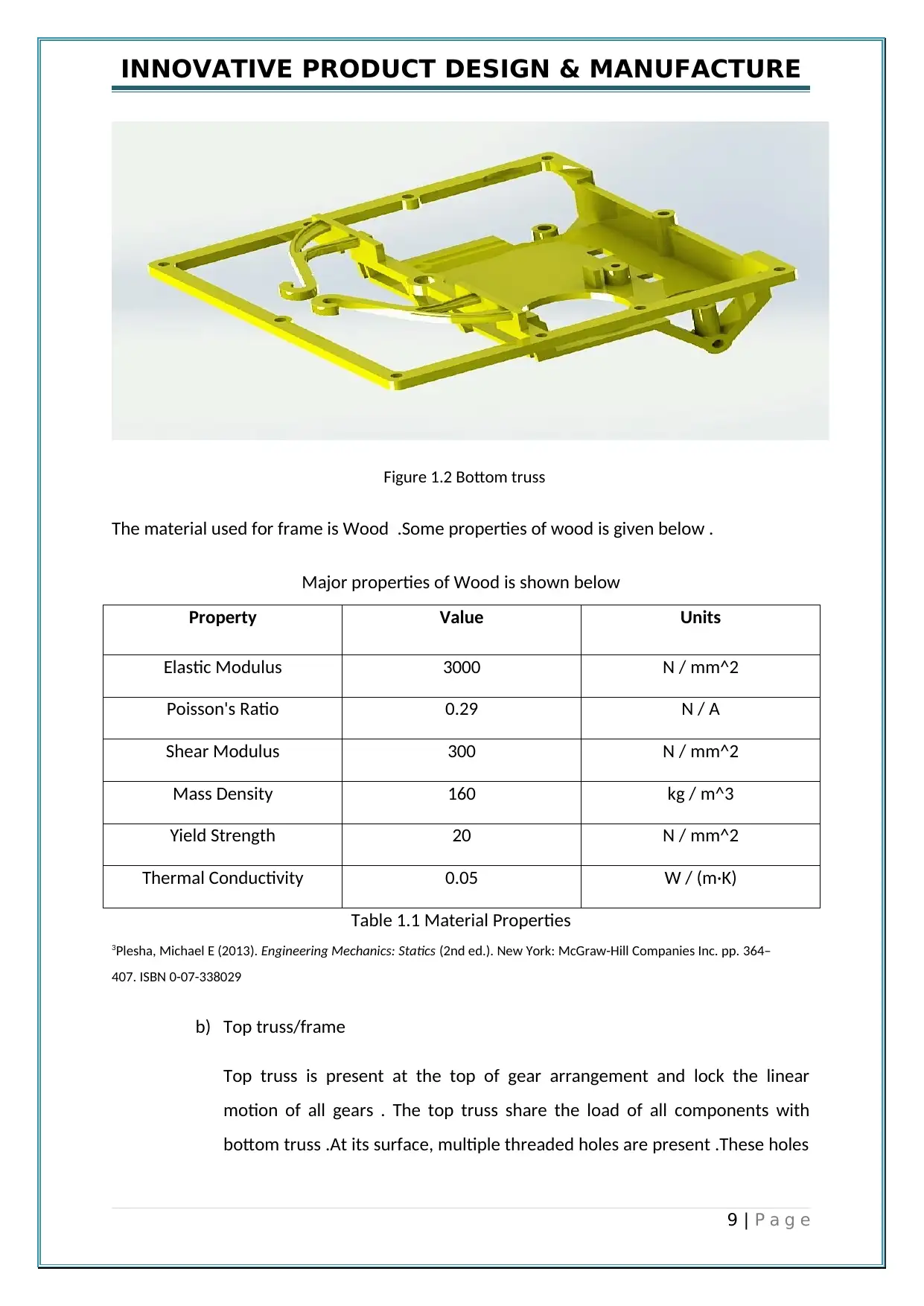
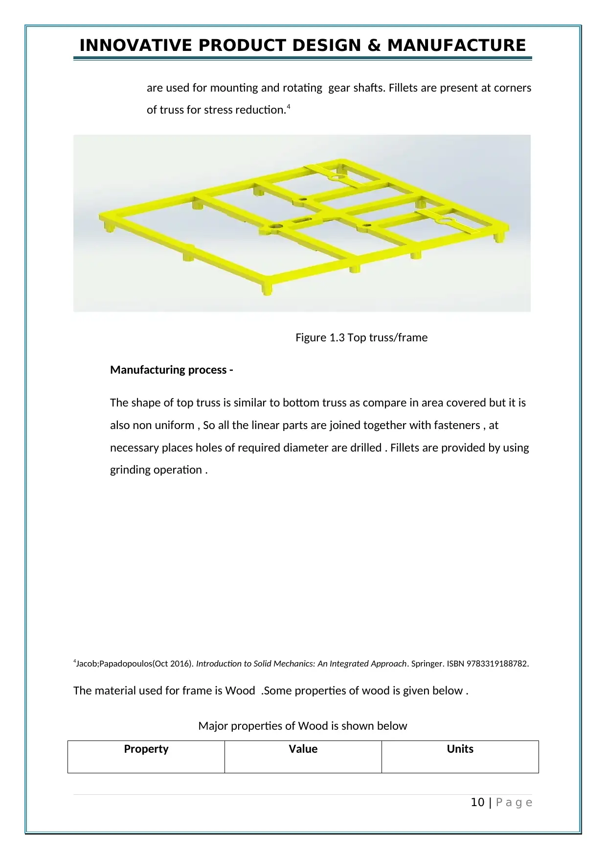
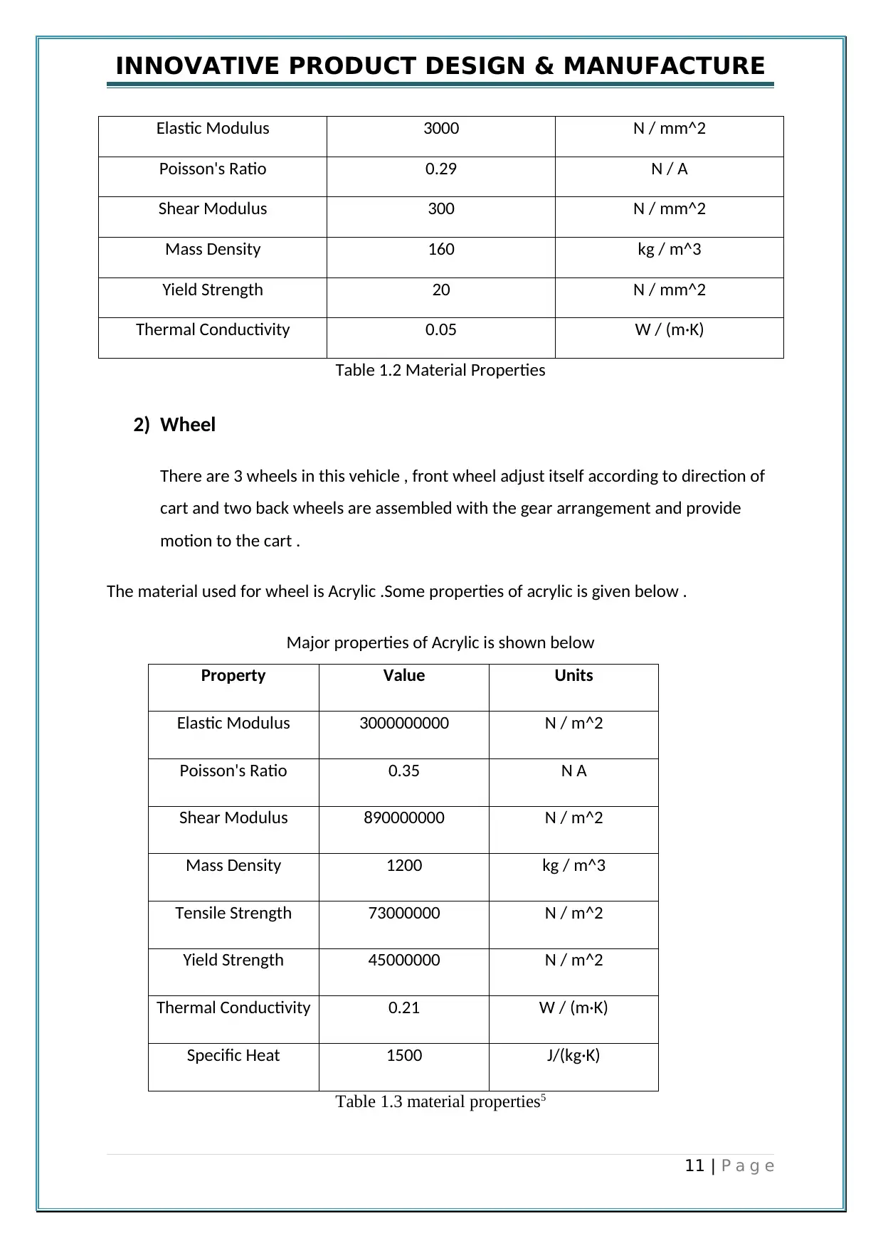
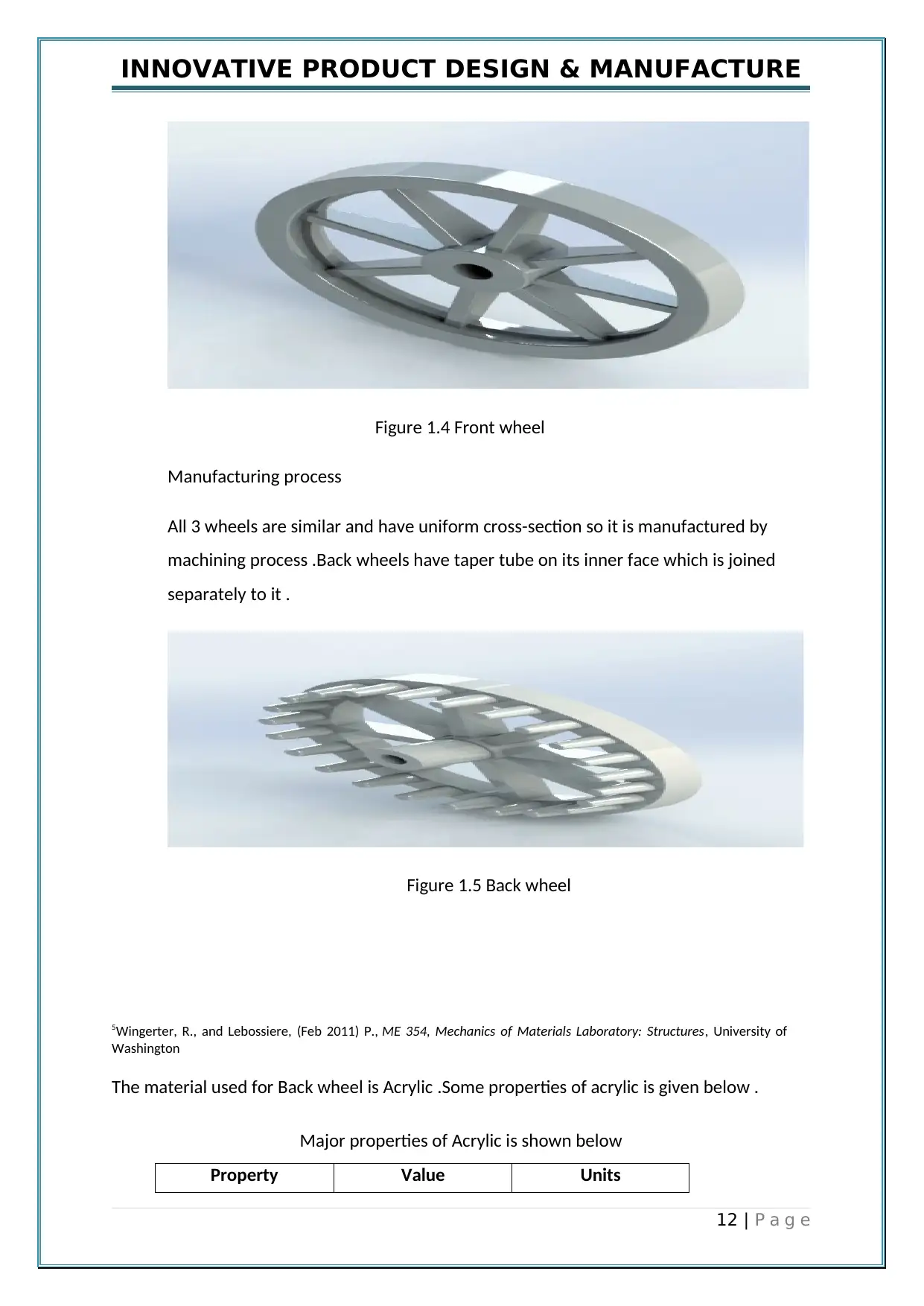
This report details the design and manufacture of a 3-wheeler cart, drawing inspiration from Leonardo da Vinci's self-propelling cart. The design process involves the creation of a prototype using CAD software, with detailed drawings and rendering for manufacturing purposes. The report provides a partial product design specification, outlining requirements for weight, ergonomics, safety, materials, and cost. Key components such as the truss/frames, wheels, and gear arrangement are specified, including material properties and manufacturing processes. The gear arrangement includes a winding unit, input gear, stepped gear shaft, cam gear, and clutch shaft. The design incorporates design for manufacture and assembly (DFMA) principles to optimize manufacturing and assembly costs. The report includes detailed design specifications, assembly drawings, and G-code for manufacturing, providing a comprehensive overview of the cart's design and manufacturing process. The cart utilizes a manual spring mechanism for power and a steering mechanism for directional control. The report also discusses the materials used and their properties.
Document Page
INNOVATIVE PRODUCT DESIGN & MANUFACTURE
REPORT
ON
THREE WHEELER CART
1 | P a g e
tabler-icon-diamond-filled.svg

Paraphrase This Document

Need a fresh take? Get an instant paraphrase of this document with our AI Paraphraser
Document Page
INNOVATIVE PRODUCT DESIGN & MANUFACTURE
Table of Contents..................................................................................................2
1. Abstract....................................................................................................3
2. Introduction.............................................................................................4
4. Design Process.........................................................................................4
5. Design Concept........................................................................................4
6. Design Specification................................................................................5
6. Design Evaluation..................................................................................17
6. DFMA principles & analysis.................................................................18
7. Design Validation..................................................................................19
8. Conclusion.............................................................................................24
9. Detailed design.......................................................................................25
9. Assembly Drawing.................................................................................28
9. G code ...................................................................................................29
10. Reference...............................................................................................36
2 | P a g e
Document Page
INNOVATIVE PRODUCT DESIGN & MANUFACTURE
Partial Product Design Specification (PPDS)
Element Description Deman
d or
Wish
Weight Not more than 7 Kilograms Deman
d
Ergonomics Design to be key activation of cart motion.
Design to be self steering ability.
Handle to accommodate by anyone.
Deman
d
Deman
d
Deman
d
Safety Design to justify standards.
Design to have no sharp corners or edges.
All the moving components are covered by
frame.
Deman
d
Deman
d
Deman
d
Materials Body of design to be made of lightweight
material such as acrylic .
Chosen acrylic material should be resistant to
wear and tear.
Deman
d
Deman
d
Product Cost Design to fit into the $50. Wish
Life in
Service
A minimum of 2 years is required. Deman
d
Maintenance Design is maintenance free. Deman
d
Aesthetics Frame of cart coloured with blue , red or green . Deman
d
Size Overall length is maximum to 600 mm.
Width to be no more than 400 mm.
Deman
d
Deman
3 | P a g e
Document Page
INNOVATIVE PRODUCT DESIGN & MANUFACTURE
Height to be no more than 400 mm d
Deman
d
Performance Design must be easy to operate.
Design must be easy to attach and remove
attachments.
Deman
d
Deman
d
ABSTRACT
Under this report ,design of 3 wheeler cart is done by using Computer aided design .This
cart is first created by Leonardo da Vinci and he named this vehicle as self propelling
cart .The prototype of this cart is recreated in this report .The manual spring mechanism is
used to power this cart as a key is directly connected to spring .When the key is rotated
then spring get compressed and absorb the energy then spring transfers the energy to gear
arrangement which is directly connected to wheels of cart .The front wheel is design in such
a way to steer it accordingly .
4 | P a g e
tabler-icon-diamond-filled.svg

Paraphrase This Document

Need a fresh take? Get an instant paraphrase of this document with our AI Paraphraser
Document Page
INNOVATIVE PRODUCT DESIGN & MANUFACTURE
INTRODUCTION
Da Vinci was not only designer but also an artist and a painter and that also reflect in his
work as well .His one of the best work was propelling cart and this cart was impossible of
design at that time without necessary resources .This cart is a masterpiece having perfect
use of gears .All the parts of cart were recreated using solidworks CAD software . Rendering
and detailed drawing of all parts are prepared for manufacturing purpose . Analysis of
wheel of cart is done and comparing it for prototyping purpose and cnc manufacturing .
DESIGN PROCESS
The main focus of design process is to recreate the prototype of 3 wheeler cart effectively
considering all design aspects .
DESIGN CONCEPT/SKETCH
Wheel
5 | P a g e
Document Page
INNOVATIVE PRODUCT DESIGN & MANUFACTURE
Wheel provide the rolling motion to cart , the spokes present on its centre balance center of
gravity of wheel .
Frame
Frame cover all the mechanical components used in cart and support the weight of it .
Gears
Gear transfer the motion from one part to other .
Cart
6 | P a g e
Document Page
INNOVATIVE PRODUCT DESIGN & MANUFACTURE
Figure 1.1 Cart design concept
Under the design concept , a rough sketch of 3 wheeler cart is obtained. This sketch
gives us the basic idea about the product visualization. The above sketch shows that
gears assembly is surrounded by frame .This frame not only kept all the parts
together but also carry out all the load act upon it .1
1 Davinci, Leonardo (2011). The Notebooks of Leonardo Da Vinci. Lulu. p. 736.
3 Wheeler cart should be designed similar to propelling cart and all the main
components like spring , gears and frame should be used accordingly .
3 Wheels are used in this cart , front single wheels is used for direction purpose and
backward two wheels provide the motion .2
DESIGN SPECIFICATION
Under design specification all the parts of 3 wheeler car should be specify accordingly . All
the component are explained below .
1) Truss/Frames
7 | P a g e
tabler-icon-diamond-filled.svg

Paraphrase This Document

Need a fresh take? Get an instant paraphrase of this document with our AI Paraphraser
Document Page
INNOVATIVE PRODUCT DESIGN & MANUFACTURE
Truss/Frames are the structure members generally used to carry loads and coupled
multiple parts in single unit for smooth operation of assembly. To carry the weight of
multiple gear units , here two types of truss are used .
Truss/Frames used are:-
a) Bottom Truss/frame
b) Top Truss/frame
a) Bottom truss
According to its name suggest ,bottom truss present at the bottom of gear
assembly .The load of all mechanical components are directly act on this
truss .At the surface of bottom truss , multiple threaded holes are
present .These holes are used for mounting and rotating gear shafts . Other
holes are used to fastened the bolts with other frame . Fillets are present at
corners of truss for stress reduction.
2Fernando (2010). Technological Concepts and Mathematical Models in the Evolution of Modern Engineering
Systems.Birkhäuser. ISBN 978-3-7643-6940-8.
Manufacturing process -
The shape of frame is non uniform , So all the linear parts are joined together with
fasteners , at necessary places holes of required diameter are drilled . Fillets are
provided by using grinding operation .3
8 | P a g e
Document Page
INNOVATIVE PRODUCT DESIGN & MANUFACTURE
Figure 1.2 Bottom truss
The material used for frame is Wood .Some properties of wood is given below .
Major properties of Wood is shown below
Property Value Units
Elastic Modulus 3000 N / mm^2
Poisson's Ratio 0.29 N / A
Shear Modulus 300 N / mm^2
Mass Density 160 kg / m^3
Yield Strength 20 N / mm^2
Thermal Conductivity 0.05 W / (m·K)
Table 1.1 Material Properties
3Plesha, Michael E (2013). Engineering Mechanics: Statics (2nd ed.). New York: McGraw-Hill Companies Inc. pp. 364–
407. ISBN 0-07-338029
b) Top truss/frame
Top truss is present at the top of gear arrangement and lock the linear
motion of all gears . The top truss share the load of all components with
bottom truss .At its surface, multiple threaded holes are present .These holes
9 | P a g e
Document Page
INNOVATIVE PRODUCT DESIGN & MANUFACTURE
are used for mounting and rotating gear shafts. Fillets are present at corners
of truss for stress reduction.4
Figure 1.3 Top truss/frame
Manufacturing process -
The shape of top truss is similar to bottom truss as compare in area covered but it is
also non uniform , So all the linear parts are joined together with fasteners , at
necessary places holes of required diameter are drilled . Fillets are provided by using
grinding operation .
4Jacob;Papadopoulos(Oct 2016). Introduction to Solid Mechanics: An Integrated Approach. Springer. ISBN 9783319188782.
The material used for frame is Wood .Some properties of wood is given below .
Major properties of Wood is shown below
Property Value Units
10 | P a g e
tabler-icon-diamond-filled.svg

Paraphrase This Document

Need a fresh take? Get an instant paraphrase of this document with our AI Paraphraser
Document Page
INNOVATIVE PRODUCT DESIGN & MANUFACTURE
Elastic Modulus 3000 N / mm^2
Poisson's Ratio 0.29 N / A
Shear Modulus 300 N / mm^2
Mass Density 160 kg / m^3
Yield Strength 20 N / mm^2
Thermal Conductivity 0.05 W / (m·K)
Table 1.2 Material Properties
2) Wheel
There are 3 wheels in this vehicle , front wheel adjust itself according to direction of
cart and two back wheels are assembled with the gear arrangement and provide
motion to the cart .
The material used for wheel is Acrylic .Some properties of acrylic is given below .
Major properties of Acrylic is shown below
Property Value Units
Elastic Modulus 3000000000 N / m^2
Poisson's Ratio 0.35 N A
Shear Modulus 890000000 N / m^2
Mass Density 1200 kg / m^3
Tensile Strength 73000000 N / m^2
Yield Strength 45000000 N / m^2
Thermal Conductivity 0.21 W / (m·K)
Specific Heat 1500 J/(kg·K)
Table 1.3 material properties5
11 | P a g e
Document Page
INNOVATIVE PRODUCT DESIGN & MANUFACTURE
Figure 1.4 Front wheel
Manufacturing process
All 3 wheels are similar and have uniform cross-section so it is manufactured by
machining process .Back wheels have taper tube on its inner face which is joined
separately to it .
Figure 1.5 Back wheel
5Wingerter, R., and Lebossiere, (Feb 2011) P., ME 354, Mechanics of Materials Laboratory: Structures, University of
Washington
The material used for Back wheel is Acrylic .Some properties of acrylic is given below .
Major properties of Acrylic is shown below
Property Value Units
12 | P a g e
chevron_up_icon
1 out of 41
circle_padding
hide_on_mobile
zoom_out_icon
[object Object]