Project: Application of Mechanical Control for Quad Bike Drive-Line

Verified

Added on  2023/06/08

|20
|1928
|280
Project
AI Summary
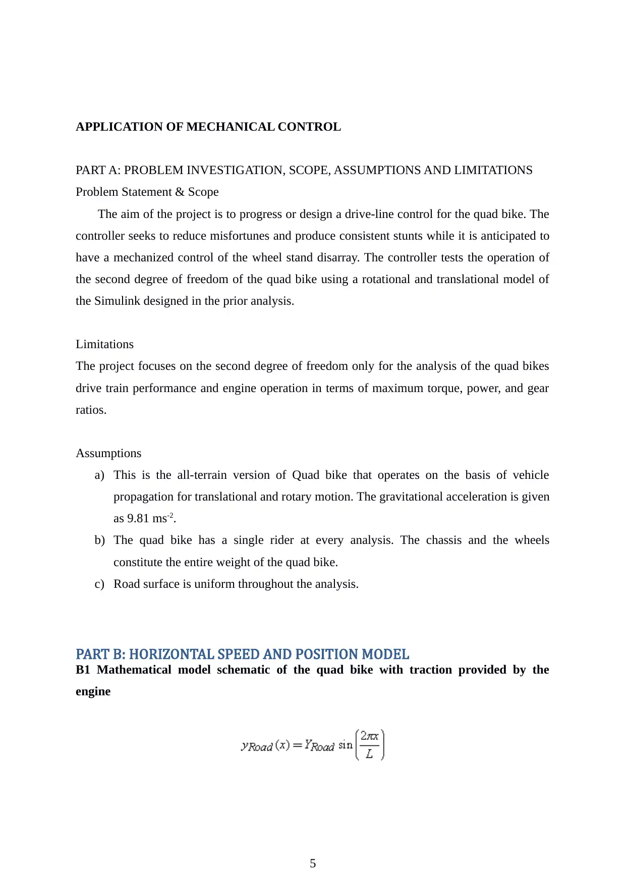
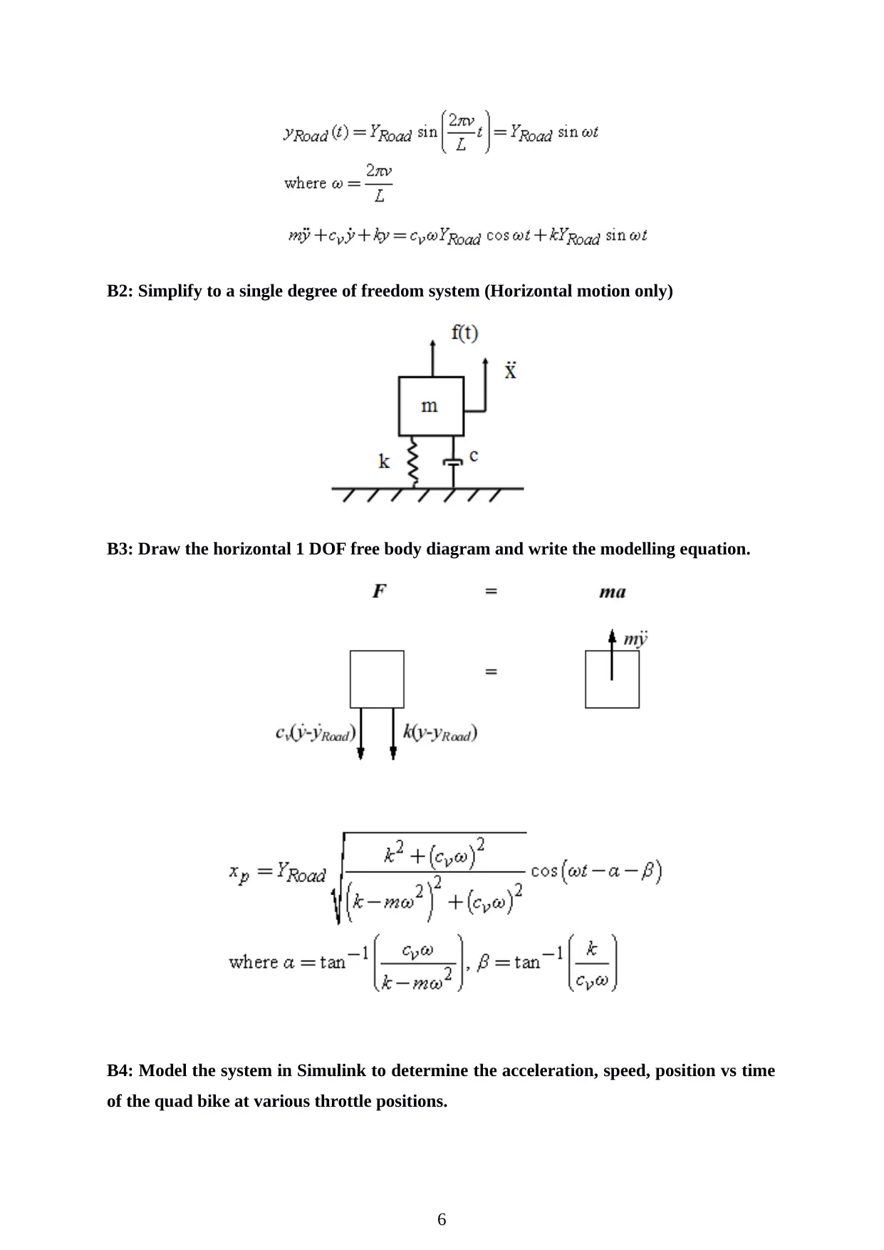
This project focuses on designing and analyzing a drive-line control system for a quad bike to improve performance and reduce mishaps, particularly focusing on wheel stand control. The project begins with problem investigation, scope definition, and assumptions, followed by the development of horizontal speed and position models. A two-degree-of-freedom model incorporating vertical and pitch dynamics is then developed, including a PID controller for wheel stand control. The project progresses to incorporate engine power and torque limitations, road surface variations, and payload changes. Further improvements involve re-assessing spring and damper values and analyzing the stability of the final model using root locus plots. The findings include how a controller stabilizes the system in the presence of noise. The project concludes with discussions on the benefits of the controller, design recommendations for suspension and controller parameters, and steps for implementing the controller on a real quad bike. The project also explores the benefits of using a PID controller to ensure optimum control dynamics to obtain zero steady state error, faster response which implies a shorter rise time, no oscillations, no overshoots, and higher stability.
Document Page
PROJECT TWO:
APPLICATION OF MECHANICAL CONTROL
ENEM20001
INSTITUTIONAL AFFILIATION
LOCATION (STATE, COUNTRY)
STUDENT NAME
STUDENT ID NUMBER
PROFESSOR (TUTOR)
DATE OF SUBMISSION
1
tabler-icon-diamond-filled.svg

Paraphrase This Document

Need a fresh take? Get an instant paraphrase of this document with our AI Paraphraser
Document Page
2
Document Page
3
Document Page
TABLE OF CONTENTS
4
tabler-icon-diamond-filled.svg

Paraphrase This Document

Need a fresh take? Get an instant paraphrase of this document with our AI Paraphraser
Document Page
APPLICATION OF MECHANICAL CONTROL
PART A: PROBLEM INVESTIGATION, SCOPE, ASSUMPTIONS AND LIMITATIONS
Problem Statement & Scope
The aim of the project is to progress or design a drive-line control for the quad bike. The
controller seeks to reduce misfortunes and produce consistent stunts while it is anticipated to
have a mechanized control of the wheel stand disarray. The controller tests the operation of
the second degree of freedom of the quad bike using a rotational and translational model of
the Simulink designed in the prior analysis.
Limitations
The project focuses on the second degree of freedom only for the analysis of the quad bikes
drive train performance and engine operation in terms of maximum torque, power, and gear
ratios.
Assumptions
a) This is the all-terrain version of Quad bike that operates on the basis of vehicle
propagation for translational and rotary motion. The gravitational acceleration is given
as 9.81 ms-2.
b) The quad bike has a single rider at every analysis. The chassis and the wheels
constitute the entire weight of the quad bike.
c) Road surface is uniform throughout the analysis.
PART B: HORIZONTAL SPEED AND POSITION MODEL
B1 Mathematical model schematic of the quad bike with traction provided by the
engine
5
Document Page
B2: Simplify to a single degree of freedom system (Horizontal motion only)
B3: Draw the horizontal 1 DOF free body diagram and write the modelling equation.
B4: Model the system in Simulink to determine the acceleration, speed, position vs time
of the quad bike at various throttle positions.
6
Document Page
B5: Simulink results are compared with theoretical computations of the model.
B6: conclusive discussion
There is a lag before rise time. This could mean that the quad bike takes some time before it
accelerates to certain speeds. Such an engine performance is undesirable hence there is need
for better control measures that will monitor the operation of the system and reduce the rise
time as well as the overshoot.
7
tabler-icon-diamond-filled.svg

Paraphrase This Document

Need a fresh take? Get an instant paraphrase of this document with our AI Paraphraser
Document Page
PART C: TWO DEGREE OF FREEDOM MODEL WITH CONTROLLER
(VERTICAL AND PITCH)
C1: Estimation the center of gravity location of the rider and payload variations.
Payload variations
Parameter Value
Rider mass 67 kg (670N)
Payload mass 3140 kg (31400N)
Location Adelaide, Australia
Mass variations 45-56 kg
Road variations 6m ~0.02 m
C1- suspension spring stiffness 25000 (N/m)
B1- suspension absorber damping 1000 (Ns/m)
C2- front axle bellows stiffness 300,000 (N/m)
C.2 Draw the simplified model schematic and the 2 DOF FBD and write the modeling
equations
8
Document Page
C3 creating a suitable 2DOF simulink model.
C.4 Adding a feedback loop of PID controller to the model to achieve a wheel stand on
level ground
9
Document Page
C.5 Determining the engine or drive train forces and wheel-road friction levels required
for the different controllers and the assumed maximum capacities of the engine and
wheel-road surface.
The engine or drive train forces, wheel road friction levels, the different controllers as
well as the assumed maximum capacities of the engine and wheel-road surfaces.
10
tabler-icon-diamond-filled.svg

Paraphrase This Document

Need a fresh take? Get an instant paraphrase of this document with our AI Paraphraser
Document Page
PART D: FURTHER MODEL IMPROVEMENTS
D1: Add limitations of engine power or torque and the wheel-road interface to the
model. Update controller to accommodate the limitations.
The limitations added to the system are in form of white Gaussian noise. It represents fault
engine with lower performance.
11
Document Page
D2: combine the output with the system output of the horizontal model in part B
12
chevron_up_icon
1 out of 20
circle_padding
hide_on_mobile
zoom_out_icon
[object Object]