Radio Link Microwave Transmission System: Budget and Passive Repeaters

Verified

Added on  2023/03/31

|8
|1093
|197
Homework Assignment
AI Summary
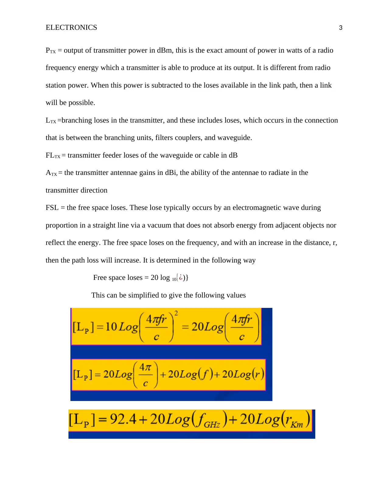
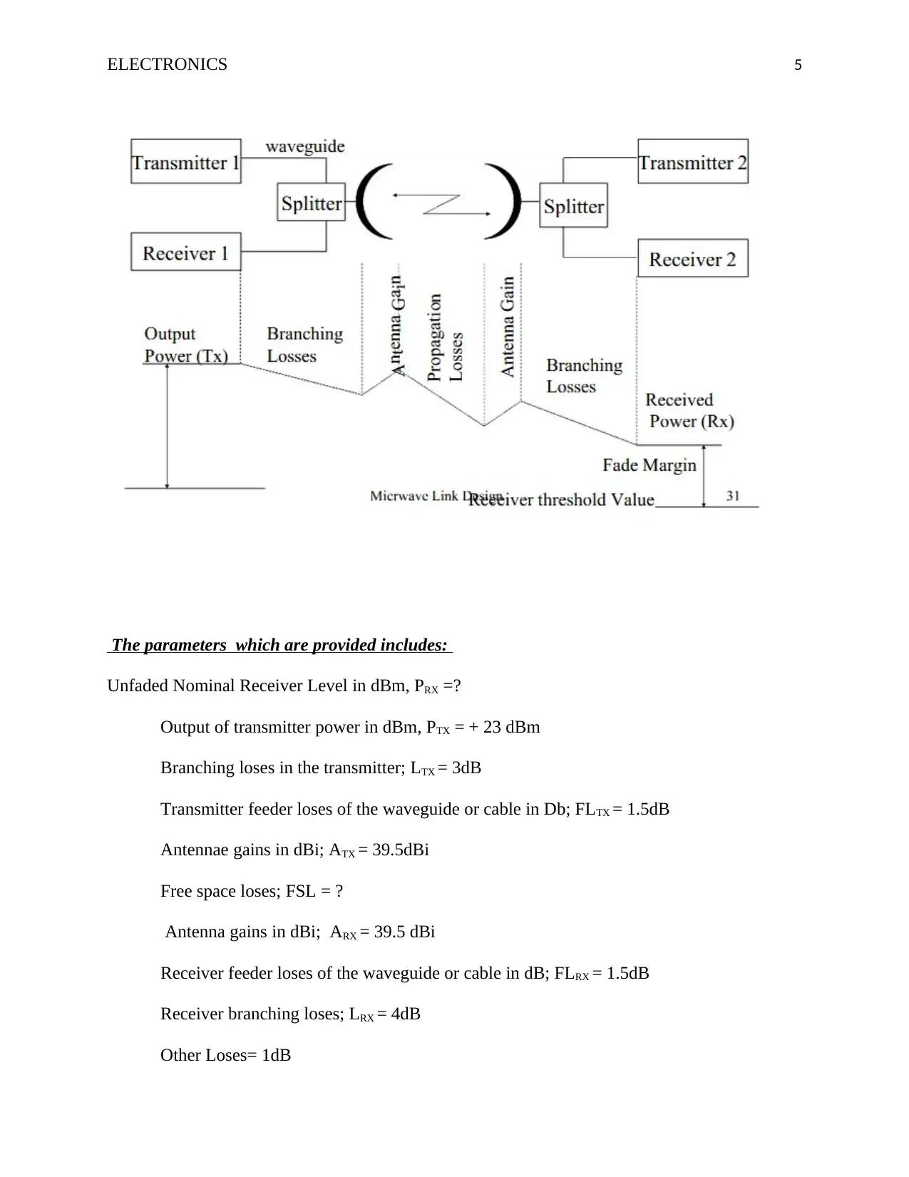
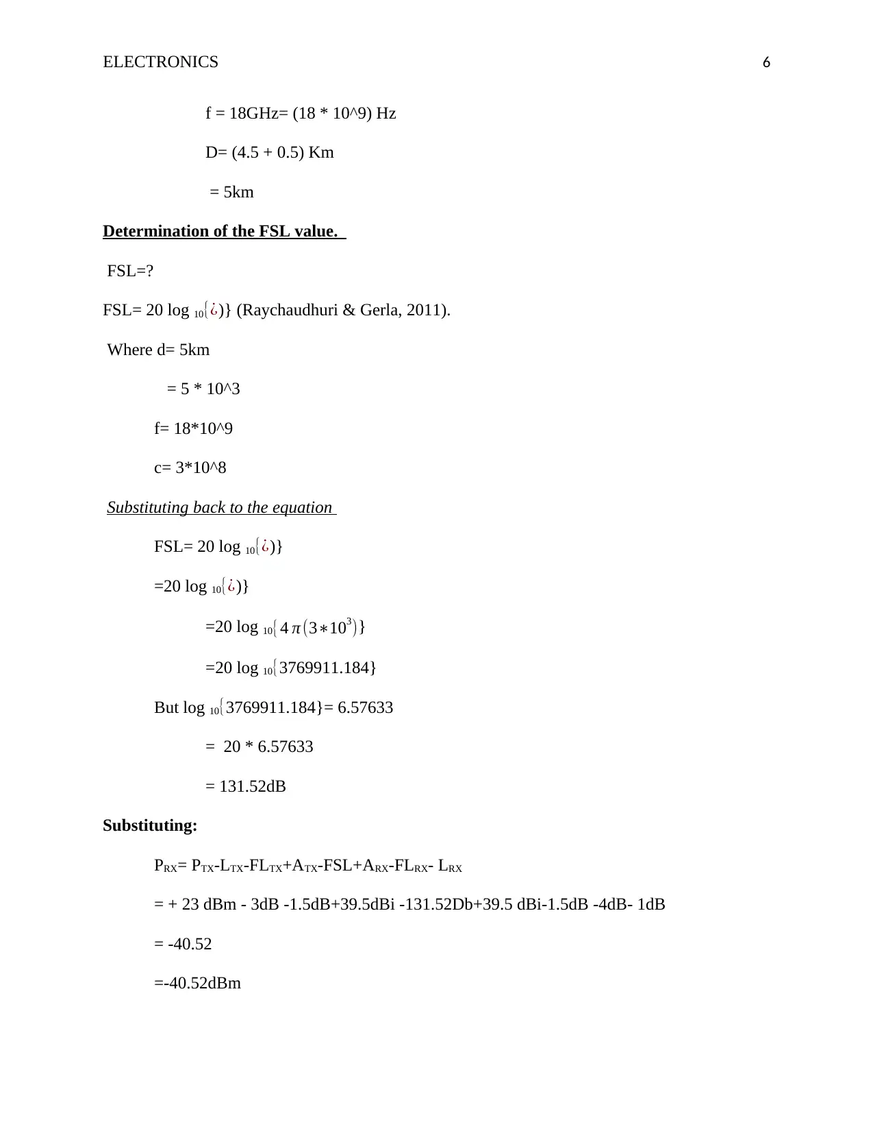
This assignment delves into the analysis of radio link microwave transmission systems, focusing on link budget calculations and the role of passive repeaters. It begins by defining the link budget as a crucial calculation involving gains and losses in transmission lines, transmitters, antennas, and the environment, which helps determine the maximum operational distance between the receiver and transmitter. The document explains key terms such as PRX (Unfaded Nominal Receiver Level), PTX (output of transmitter power), LTX (branching losses in the transmitter), FLTX (transmitter feeder losses), ATX (transmitter antenna gains), FSL (free space losses), ARX (receiver antenna gains), FLRX (receiver feeder losses), and LRX (receiver branching losses). It then calculates the Free Space Loss (FSL) using the provided frequency and distance parameters. The assignment further discusses the purpose of passive repeaters in microwave transmission, highlighting their functions as refractive or reflective panels that aid in closing microwave or radio links when signals are obstructed. It contrasts passive repeaters with active repeaters, emphasizing their simplicity, lower maintenance costs, and lack of need for electrical power or additional frequencies. Desklib offers a wealth of similar solved assignments and resources for students.
tabler-icon-diamond-filled.svg

Contribute Materials

Your contribution can guide someone’s learning journey. Share your documents today.
Document Page
Running head: ELECTRONICS 1
Electronics
Name of Student
Institution Affiliation
tabler-icon-diamond-filled.svg

Secure Best Marks with AI Grader

Need help grading? Try our AI Grader for instant feedback on your assignments.
Document Page
ELECTRONICS 2
Introduction
In order to solve this question, we first need to understand some concepts which are
involved in the radio link microwave transmission system. The quality of the equipment which is
being used determines the performance of any communication link. Thus, to quantify the
performance of the communication link, we need to determine what is known as the link budget.
By way of definition, the link budget is a calculation which comprises of the factors of loses and
gains that are present in the transmission lines, transmitters, antennas, as well as the environment
in which the signal is being transmitted. This will significantly assist in determining the
maximum distance that both the receiver and the transmitter can operate successfully. Each of
the antennae is composed of gains at each of their ends. These gains are added to the gains in the
system in order to provide a higher gain.
Additionally, during transmission of the signal, there are instances of free space loss.
These free space losses are subtracted. Fundamentally, the link is directly proportional to the
loses. For example, the longer the link, the higher the loses. Additionally, the shorter the link, the
lesser the loses associated during transmission. In most of the instances, the same duplex ratio
set up gets applied to both stations, for example, the transmitter and receiver stations. This
implies that the determination of the received signal level does not depend on the direction of the
signal.
Definition of terms
PRX= Unfaded Nominal Receiver Level in dBm- generally, this is the difference obtained after
addition of the antenna gains, receiver gains, and the output of the transmitter to the fixed loses
which are present on both side of the receiver and the transmitter.
Document Page
ELECTRONICS 3
PTX = output of transmitter power in dBm, this is the exact amount of power in watts of a radio
frequency energy which a transmitter is able to produce at its output. It is different from radio
station power. When this power is subtracted to the loses available in the link path, then a link
will be possible.
LTX =branching loses in the transmitter, and these includes loses, which occurs in the connection
that is between the branching units, filters couplers, and waveguide.
FLTX = transmitter feeder loses of the waveguide or cable in dB
ATX = the transmitter antennae gains in dBi, the ability of the antennae to radiate in the
transmitter direction
FSL = the free space loses. These lose typically occurs by an electromagnetic wave during
proportion in a straight line via a vacuum that does not absorb energy from adjacent objects nor
reflect the energy. The free space loses on the frequency, and with an increase in the distance, r,
then the path loss will increase. It is determined in the following way
Free space loses = 20 log 10{¿)}
This can be simplified to give the following values
Document Page
ELECTRONICS 4
ARX = the receiver antenna gains in dBi, the ability of the antennae to radiate in the
transmitter direction
FLRX =receiver feeder loses of the waveguide or cable in dB
LRX =receiver branching loses
In Unfaded conditions: the link budget is determined by the formula
PRX= PTX-LTX-FLTX+ATX-FSL+ARX-FLRX- LRX (Raychaudhuri & Gerla,
2011).
Where PRX= Unfaded Nominal Receiver Level in dBm
PTX = output of transmitter power in dBm
LTX =branching loses in the transmitter
FLTX = transmitter feeder loses of the waveguide or cable in dB
ATX = the antennae gains in dBi
FSL = the free space loses
ARX = the antenna gains in dBi ,
FLRX =receiver feeder loses of the waveguide or cable in dB
LRX =receiver branching loses
We will use a radio path link budget diagram in order to analyses our system. Below is the
illustration
tabler-icon-diamond-filled.svg

Secure Best Marks with AI Grader

Need help grading? Try our AI Grader for instant feedback on your assignments.
Document Page
ELECTRONICS 5
The parameters which are provided includes:
Unfaded Nominal Receiver Level in dBm, PRX =?
Output of transmitter power in dBm, PTX = + 23 dBm
Branching loses in the transmitter; LTX = 3dB
Transmitter feeder loses of the waveguide or cable in Db; FLTX = 1.5dB
Antennae gains in dBi; ATX = 39.5dBi
Free space loses; FSL = ?
Antenna gains in dBi; ARX = 39.5 dBi
Receiver feeder loses of the waveguide or cable in dB; FLRX = 1.5dB
Receiver branching loses; LRX = 4dB
Other Loses= 1dB
Document Page
ELECTRONICS 6
f = 18GHz= (18 * 10^9) Hz
D= (4.5 + 0.5) Km
= 5km
Determination of the FSL value.
FSL=?
FSL= 20 log 10{¿)} (Raychaudhuri & Gerla, 2011).
Where d= 5km
= 5 * 10^3
f= 18*10^9
c= 3*10^8
Substituting back to the equation
FSL= 20 log 10{¿)}
=20 log 10{¿)}
=20 log 10{4 π (3103)}
=20 log 10{3769911.184}
But log 10{3769911.184}= 6.57633
= 20 * 6.57633
= 131.52dB
Substituting:
PRX= PTX-LTX-FLTX+ATX-FSL+ARX-FLRX- LRX
= + 23 dBm - 3dB -1.5dB+39.5dBi -131.52Db+39.5 dBi-1.5dB -4dB- 1dB
= -40.52
=-40.52dBm
Document Page
ELECTRONICS 7
Q2: Purpose of passive repeaters in the microwave transmission
A passive repeater is also known as passive radio link deflection. It performs three
functions, for instance, it either acts a refractive panel, a reflective panel or just an object which
helps in closing a microwave or radio link, in instances that a certain object has obstructed a
signal. In comparison to the active repeater, the passive repeater is very simple and does not
require high maintenance costs. Besides, they do not need any site electrical power nor additional
frequencies. This makes it different from the active repeater stations which adopt various
transmit and receive frequencies in order to prevent feedback. In the vertical signal, the passive
repeater link can be achieved by utilizing a parabolic antenna to receive the signal and then
leading the signal via a waveguide to a second parabolic antenna, where it gets radiated. On the
other hand, flat surfaces may be used for the deflections of the passive repeater in a horizontal
direction. This makes the angle of the reflected beam to correspond with the relayed signal.
The whole system would comprise, of a repeater, for instance: receiver, amplifier,
isolator, and the antennae. For this system, the passive repeaters are meant to redirect the signals
which have been obstructed by any obstacle after transmission (Dar et al., 2010).
tabler-icon-diamond-filled.svg

Paraphrase This Document

Need a fresh take? Get an instant paraphrase of this document with our AI Paraphraser
Document Page
ELECTRONICS 8
References
Dar, K., Bakhouya, M., Gaber, J., Wack, M., & Lorenz, P. (2010). Wireless communication
technologies for ITS applications [Topics in Automotive Networking]. IEEE
Communications Magazine, 48(5), 156-162.
Raychaudhuri, D., & Gerla, M. (Eds.). (2011). Emerging wireless technologies and future
mobile internet. Cambridge University Press.
chevron_up_icon
1 out of 8
circle_padding
hide_on_mobile
zoom_out_icon
logo.png

Your All-in-One AI-Powered Toolkit for Academic Success.

Available 24*7 on WhatsApp / Email

[object Object]