Radio over Fiber Technology: Advanced Optical Communication Report
VerifiedAdded on 2023/06/12
|18
|4234
|395
Report
AI Summary
This report provides an overview of optical communication systems, focusing on Radio over Fiber (RoF) technology. It begins by describing a general optical transmission link, highlighting the role of optical fibers, transmitters, receivers, and amplifiers. The report details the principles of optical fiber communication, including refractive index and total internal reflection, and introduces RoF systems as a means to distribute RF signals over optical fiber. It discusses the advantages of RoF, such as centralized signal processing, simpler base stations, and improved spectral efficiency. The report also touches on photonic analog-to-digital and digital-to-analog conversions, the application of RoF in local area networks, and the use of Erbium-Doped Fiber Amplifiers (EDFA) to boost signal intensity. The document emphasizes the potential of RoF to support multiple services on a single fiber and its suitability for future communication technologies, particularly in the mm-wave band.
UNIVERSITY AFFILIATION
DEPARTMENT OR FACULTY
COURSE NAME & ID
TITLE:
ADVANCED OPTICAL COMMUNICATION
STUDENT NAME
STUDENT REGISTRATION NUMBER
DATE OF SUBMISSION
[Year]
DEPARTMENT OR FACULTY
COURSE NAME & ID
TITLE:
ADVANCED OPTICAL COMMUNICATION
STUDENT NAME
STUDENT REGISTRATION NUMBER
DATE OF SUBMISSION
[Year]
Paraphrase This Document
Need a fresh take? Get an instant paraphrase of this document with our AI Paraphraser
INTRODUCTION
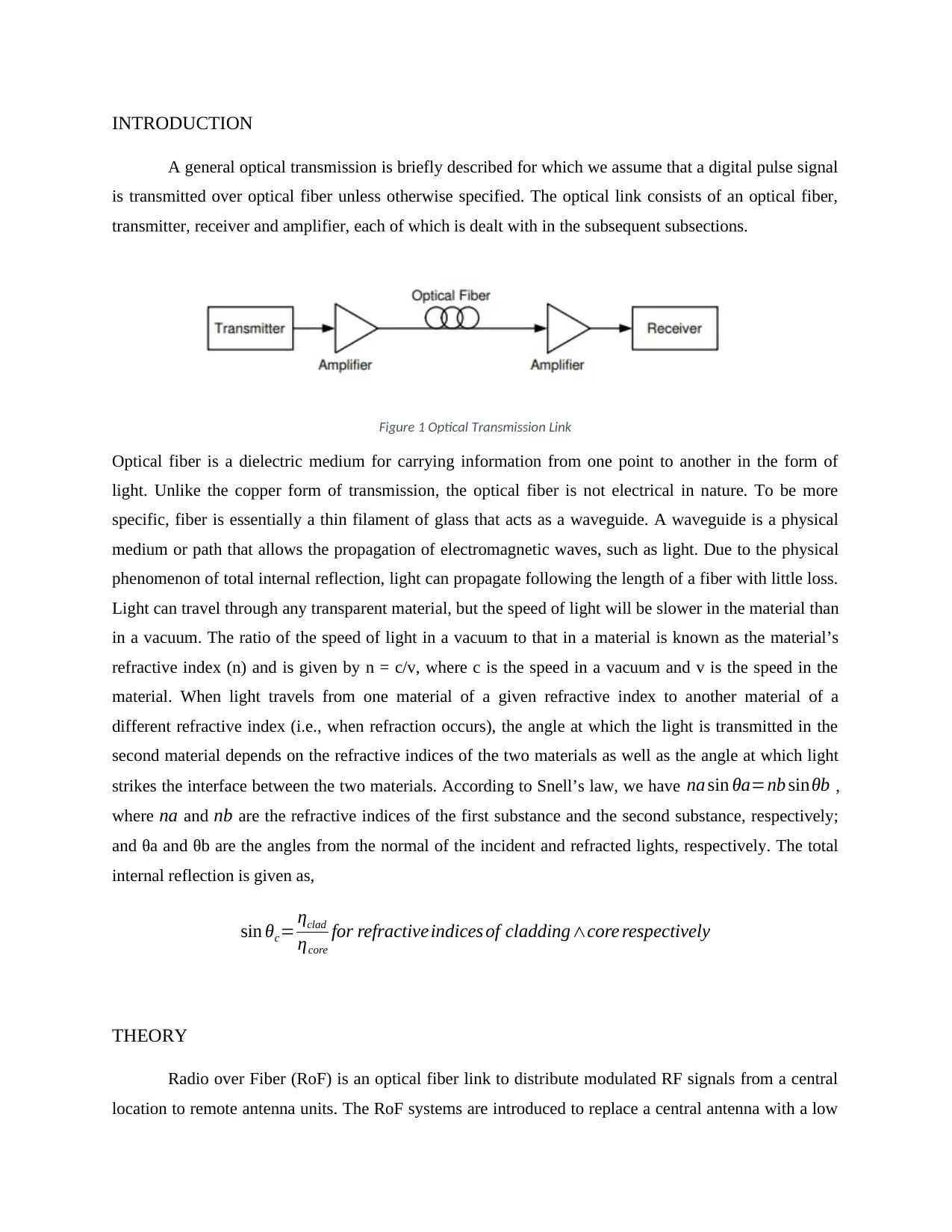
A general optical transmission is briefly described for which we assume that a digital pulse signal
is transmitted over optical fiber unless otherwise specified. The optical link consists of an optical fiber,
transmitter, receiver and amplifier, each of which is dealt with in the subsequent subsections.
Figure 1 Optical Transmission Link
Optical fiber is a dielectric medium for carrying information from one point to another in the form of
light. Unlike the copper form of transmission, the optical fiber is not electrical in nature. To be more
specific, fiber is essentially a thin filament of glass that acts as a waveguide. A waveguide is a physical
medium or path that allows the propagation of electromagnetic waves, such as light. Due to the physical
phenomenon of total internal reflection, light can propagate following the length of a fiber with little loss.
Light can travel through any transparent material, but the speed of light will be slower in the material than
in a vacuum. The ratio of the speed of light in a vacuum to that in a material is known as the material’s
refractive index (n) and is given by n = c/v, where c is the speed in a vacuum and v is the speed in the
material. When light travels from one material of a given refractive index to another material of a
different refractive index (i.e., when refraction occurs), the angle at which the light is transmitted in the
second material depends on the refractive indices of the two materials as well as the angle at which light
strikes the interface between the two materials. According to Snell’s law, we have na sin θa=nb sinθb ,
where na and nb are the refractive indices of the first substance and the second substance, respectively;
and θa and θb are the angles from the normal of the incident and refracted lights, respectively. The total
internal reflection is given as,
sin θc= ηclad
ηcore
for refractiveindices of cladding∧core respectively
THEORY
Radio over Fiber (RoF) is an optical fiber link to distribute modulated RF signals from a central
location to remote antenna units. The RoF systems are introduced to replace a central antenna with a low
power distributed antenna system (DAS). RoF system is consisting of many base stations, which are
connected to a single central station. RoF systems centralize the RF signal processing function in one
shared location, and use optical fiber link to distribute the RF signals to the RAUs or BSs. Fiber optic
communication system are based on the fiber optic cable which provides for extremely high data rates
which allow the very large masses of data to be transmitted at the speed of light. The fiber optic cable,
FOC, transmits data over very long distance. One very common example is the sea or ocean underground
cable that connect continents on the planet earth. According to the basic model, the bandwidth of the fiber
optic communication system determines the maximum data rate. A FOC link denotes the signal pathway
between two points using the cable. The pathway is the mode or channel that enables transmission of the
data from the sender to the receiver points. The links are often described in terms of their ability to send
and receive signals as part of the communication system. There are two modes of communication
generally referred to as the simplex and duplex. This is a classification based on the direction or flow of
data or information. For the simplex mode of communication, data flows in one direction only, for
instance, home radio communication or broadcasting. The duplex mode refers to the communication
where the sender and receiver can communicate to each other. The half-duplex allows one speaker at a
time while the full-duplex allows for information to flow both ways at the same time.
On the receiver end there is another light sensitive device that is known as the photocell or the
light detector that detects the light pulses. The photo detector converts the light pulses into an electrical
signal. The electrical pulses are amplified and reshaped back into digital form. The light sources at the
sender and receiver points must be capable of operating at the same data rate. The circuitry that drives the
light source and the circuitry that amplifies and processes the detected light must both have suitable high-
frequency response. The fiber is required to carry the information signals without distortions at the set
data rate. For the single mode transmission FOC, repeater units are used to restore the signal strength that
may attenuate while propagating. Special relay stations are used to pick up light beams, convert them
back to electrical pulses that are amplified and then they are retransmitted on another beam. There are
several stages of repeaters that may be needed over very long distances. The attenuation problem occurs
as a universal problem for all the transmission cables, for instance, the electrical copper cables.
Radio over Fiber (ROF) Technique
It is the integration of wireless and fiber optical communication technologies, and modulating
wireless signals over optical carrier for transporting over fiber optic cable. The digital ROF link
can maintain the dynamic range more independently than the optical fiber link distance. The
⊘ This is a preview!⊘
Do you want full access?
Subscribe today to unlock all pages.
Trusted by 1+ million students worldwide
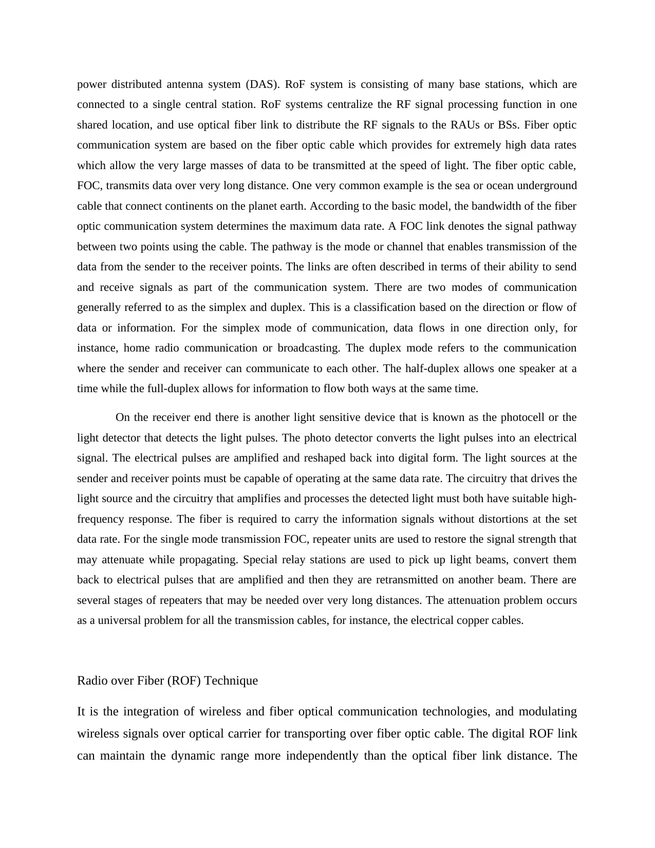
analogue radio frequency signal is digitized by using the photonic analogue-to-digital converter.
The generated digitized radio frequency data stream and RF analogue signals are transported
over optical fiber networks by using WDM technique. The photonic DAC of RF system at the
base station or the access point converts the digital photonic signals to its analogue optical
modulated signal.
The generated digitized radio frequency data stream and RF analogue signals are transported
over optical fiber networks by using WDM technique. The photonic DAC of RF system at the
base station or the access point converts the digital photonic signals to its analogue optical
modulated signal.
Paraphrase This Document
Need a fresh take? Get an instant paraphrase of this document with our AI Paraphraser
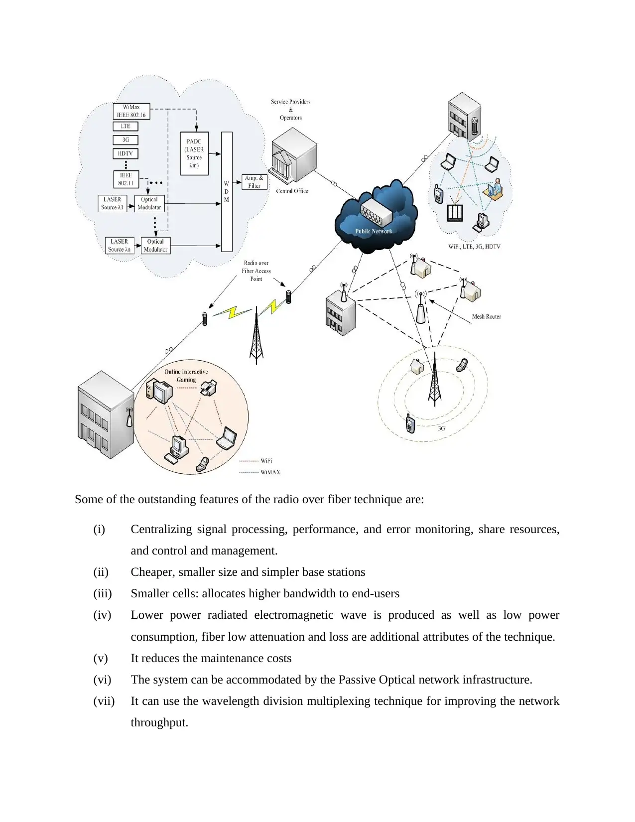
Some of the outstanding features of the radio over fiber technique are:
(i) Centralizing signal processing, performance, and error monitoring, share resources,
and control and management.
(ii) Cheaper, smaller size and simpler base stations
(iii) Smaller cells: allocates higher bandwidth to end-users
(iv) Lower power radiated electromagnetic wave is produced as well as low power
consumption, fiber low attenuation and loss are additional attributes of the technique.
(v) It reduces the maintenance costs
(vi) The system can be accommodated by the Passive Optical network infrastructure.
(vii) It can use the wavelength division multiplexing technique for improving the network
throughput.
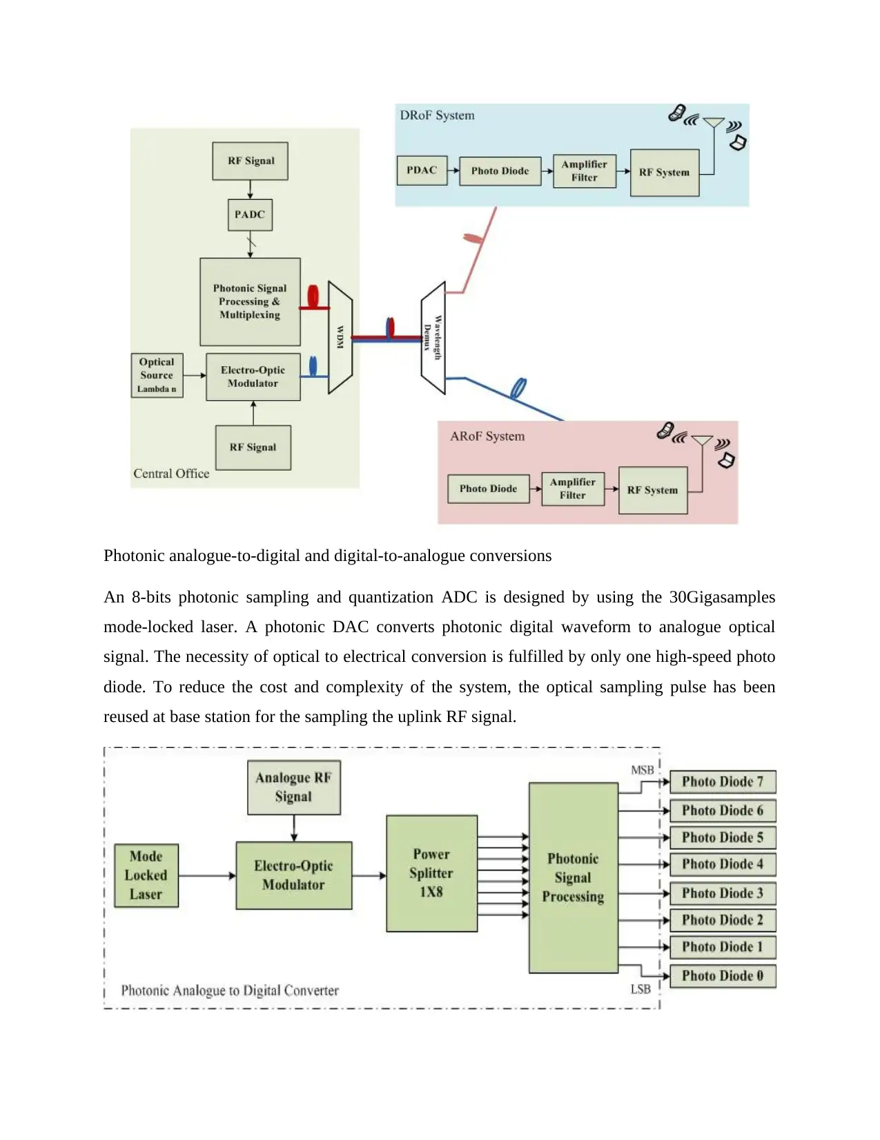
Photonic analogue-to-digital and digital-to-analogue conversions
An 8-bits photonic sampling and quantization ADC is designed by using the 30Gigasamples
mode-locked laser. A photonic DAC converts photonic digital waveform to analogue optical
signal. The necessity of optical to electrical conversion is fulfilled by only one high-speed photo
diode. To reduce the cost and complexity of the system, the optical sampling pulse has been
reused at base station for the sampling the uplink RF signal.
⊘ This is a preview!⊘
Do you want full access?
Subscribe today to unlock all pages.
Trusted by 1+ million students worldwide
The performance of the PADC is affected by the laser’s jitter and the non-linearity of the MZM,
the photonic amplifier, and the other photonic devices performance. In the digital radio over
fiber, the dynamic range is independent of the fiber length (Abdollahi, Al-Raweshidy, Fakhraie*,
& Nilavalan).
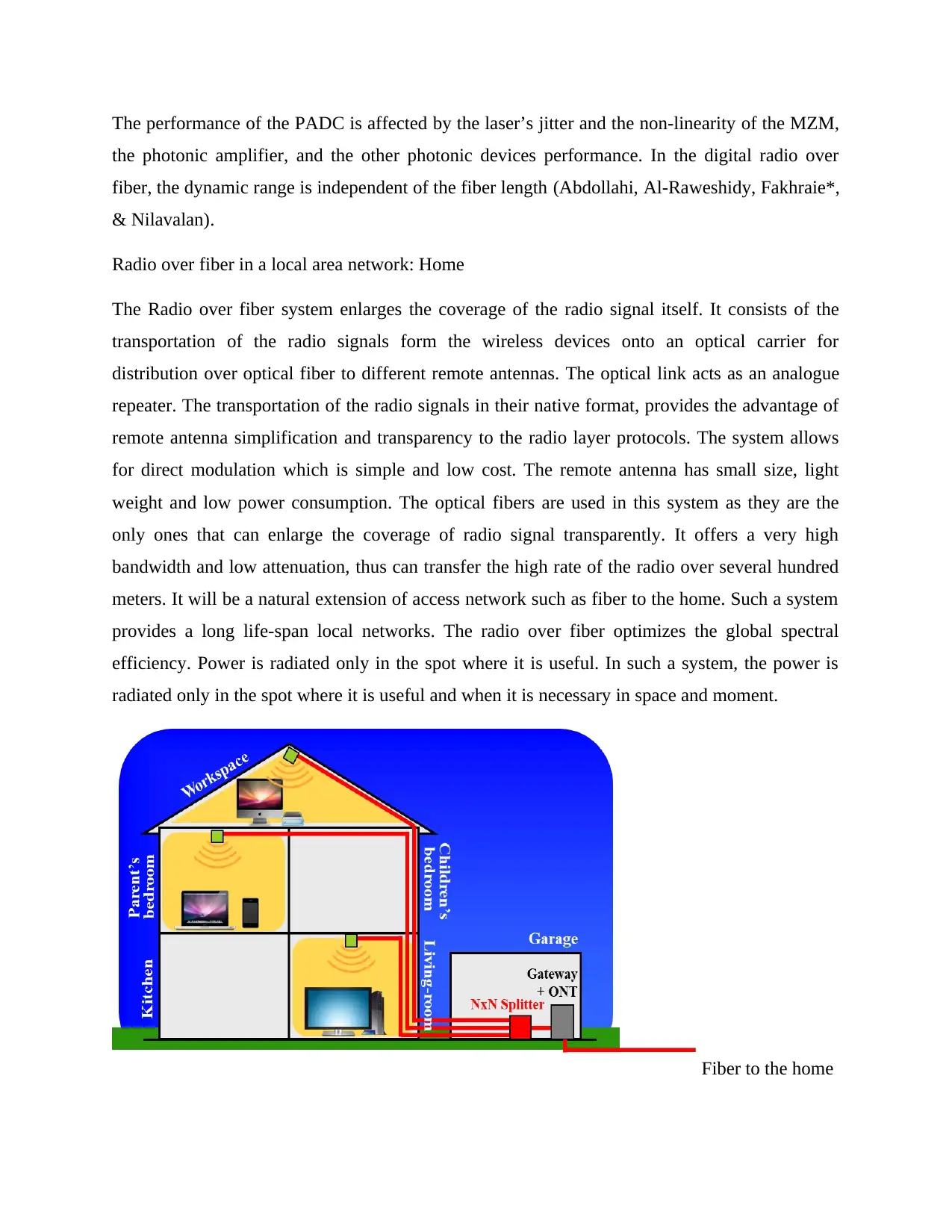
Radio over fiber in a local area network: Home
The Radio over fiber system enlarges the coverage of the radio signal itself. It consists of the
transportation of the radio signals form the wireless devices onto an optical carrier for
distribution over optical fiber to different remote antennas. The optical link acts as an analogue
repeater. The transportation of the radio signals in their native format, provides the advantage of
remote antenna simplification and transparency to the radio layer protocols. The system allows
for direct modulation which is simple and low cost. The remote antenna has small size, light
weight and low power consumption. The optical fibers are used in this system as they are the
only ones that can enlarge the coverage of radio signal transparently. It offers a very high
bandwidth and low attenuation, thus can transfer the high rate of the radio over several hundred
meters. It will be a natural extension of access network such as fiber to the home. Such a system
provides a long life-span local networks. The radio over fiber optimizes the global spectral
efficiency. Power is radiated only in the spot where it is useful. In such a system, the power is
radiated only in the spot where it is useful and when it is necessary in space and moment.
Fiber to the home
the photonic amplifier, and the other photonic devices performance. In the digital radio over
fiber, the dynamic range is independent of the fiber length (Abdollahi, Al-Raweshidy, Fakhraie*,
& Nilavalan).
Radio over fiber in a local area network: Home
The Radio over fiber system enlarges the coverage of the radio signal itself. It consists of the
transportation of the radio signals form the wireless devices onto an optical carrier for
distribution over optical fiber to different remote antennas. The optical link acts as an analogue
repeater. The transportation of the radio signals in their native format, provides the advantage of
remote antenna simplification and transparency to the radio layer protocols. The system allows
for direct modulation which is simple and low cost. The remote antenna has small size, light
weight and low power consumption. The optical fibers are used in this system as they are the
only ones that can enlarge the coverage of radio signal transparently. It offers a very high
bandwidth and low attenuation, thus can transfer the high rate of the radio over several hundred
meters. It will be a natural extension of access network such as fiber to the home. Such a system
provides a long life-span local networks. The radio over fiber optimizes the global spectral
efficiency. Power is radiated only in the spot where it is useful. In such a system, the power is
radiated only in the spot where it is useful and when it is necessary in space and moment.
Fiber to the home
Paraphrase This Document
Need a fresh take? Get an instant paraphrase of this document with our AI Paraphraser
In a system that takes the optical architecture of multipoint-to-multipoint. Using the radio MAC
layer for driving the optical infrastructure the lasers are turned on without seeing the radio data at
the input, are noise for the photodiodes that receive the optical signal from another laser. The
interferences tend to beat between independent light sources. In this case study, only one of the
devices demodulates the radio signal. It recovers the useful data in the radio MAC layer to
manage the optical access by turning on laser or photodiode. It sends instructions to remote
antenna by a monitoring signal. The radio over fiber optimizes the global spectral efficiency.
The optical architectures show good results, and need information from radio MAC layer to be
managed.
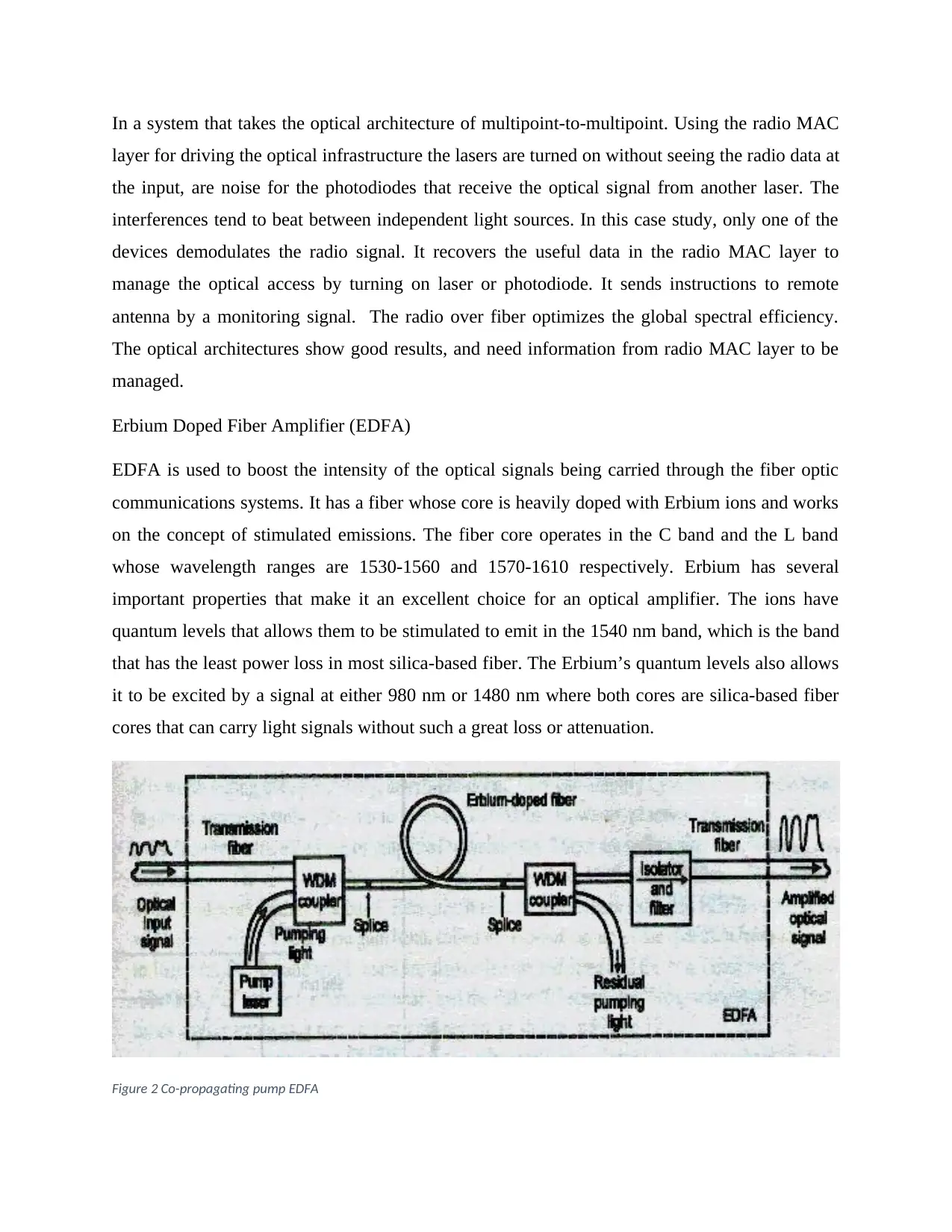
Erbium Doped Fiber Amplifier (EDFA)
EDFA is used to boost the intensity of the optical signals being carried through the fiber optic
communications systems. It has a fiber whose core is heavily doped with Erbium ions and works
on the concept of stimulated emissions. The fiber core operates in the C band and the L band
whose wavelength ranges are 1530-1560 and 1570-1610 respectively. Erbium has several
important properties that make it an excellent choice for an optical amplifier. The ions have
quantum levels that allows them to be stimulated to emit in the 1540 nm band, which is the band
that has the least power loss in most silica-based fiber. The Erbium’s quantum levels also allows
it to be excited by a signal at either 980 nm or 1480 nm where both cores are silica-based fiber
cores that can carry light signals without such a great loss or attenuation.
Figure 2 Co-propagating pump EDFA
layer for driving the optical infrastructure the lasers are turned on without seeing the radio data at
the input, are noise for the photodiodes that receive the optical signal from another laser. The
interferences tend to beat between independent light sources. In this case study, only one of the
devices demodulates the radio signal. It recovers the useful data in the radio MAC layer to
manage the optical access by turning on laser or photodiode. It sends instructions to remote
antenna by a monitoring signal. The radio over fiber optimizes the global spectral efficiency.
The optical architectures show good results, and need information from radio MAC layer to be
managed.
Erbium Doped Fiber Amplifier (EDFA)
EDFA is used to boost the intensity of the optical signals being carried through the fiber optic
communications systems. It has a fiber whose core is heavily doped with Erbium ions and works
on the concept of stimulated emissions. The fiber core operates in the C band and the L band
whose wavelength ranges are 1530-1560 and 1570-1610 respectively. Erbium has several
important properties that make it an excellent choice for an optical amplifier. The ions have
quantum levels that allows them to be stimulated to emit in the 1540 nm band, which is the band
that has the least power loss in most silica-based fiber. The Erbium’s quantum levels also allows
it to be excited by a signal at either 980 nm or 1480 nm where both cores are silica-based fiber
cores that can carry light signals without such a great loss or attenuation.
Figure 2 Co-propagating pump EDFA
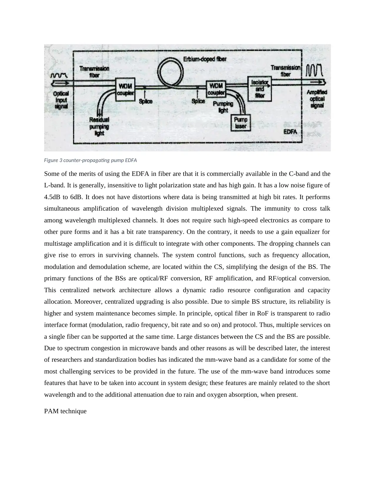
Figure 3 counter-propagating pump EDFA
Some of the merits of using the EDFA in fiber are that it is commercially available in the C-band and the
L-band. It is generally, insensitive to light polarization state and has high gain. It has a low noise figure of
4.5dB to 6dB. It does not have distortions where data is being transmitted at high bit rates. It performs
simultaneous amplification of wavelength division multiplexed signals. The immunity to cross talk
among wavelength multiplexed channels. It does not require such high-speed electronics as compare to
other pure forms and it has a bit rate transparency. On the contrary, it needs to use a gain equalizer for
multistage amplification and it is difficult to integrate with other components. The dropping channels can
give rise to errors in surviving channels. The system control functions, such as frequency allocation,
modulation and demodulation scheme, are located within the CS, simplifying the design of the BS. The
primary functions of the BSs are optical/RF conversion, RF amplification, and RF/optical conversion.
This centralized network architecture allows a dynamic radio resource configuration and capacity
allocation. Moreover, centralized upgrading is also possible. Due to simple BS structure, its reliability is
higher and system maintenance becomes simple. In principle, optical fiber in RoF is transparent to radio
interface format (modulation, radio frequency, bit rate and so on) and protocol. Thus, multiple services on
a single fiber can be supported at the same time. Large distances between the CS and the BS are possible.
Due to spectrum congestion in microwave bands and other reasons as will be described later, the interest
of researchers and standardization bodies has indicated the mm-wave band as a candidate for some of the
most challenging services to be provided in the future. The use of the mm-wave band introduces some
features that have to be taken into account in system design; these features are mainly related to the short
wavelength and to the additional attenuation due to rain and oxygen absorption, when present.
PAM technique
⊘ This is a preview!⊘
Do you want full access?
Subscribe today to unlock all pages.
Trusted by 1+ million students worldwide
Dispersion in fiber
It refers to the widening of the light pulse during propagation as it travels through a fiber. As a pulse
widens, it can broaden enough to interfere with neighboring pulses on the fiber which may cause the
inter-symbol interference. The dispersion tends to limit the bit spacing and the maximum transmission
rate on the fiber optic cable or channel. Another form of dispersion is material or chromatic dispersion. In
a dispersive medium, the index of refraction is a function of the wavelength. Thus, if the transmitted
signal consists of more than one wavelength, certain wavelengths will propagate faster than other
wavelengths. Since no laser can create a signal consisting of an exact single wavelength, chromatic
dispersion will occur in most systems. A third type of dispersion is waveguide dispersion. Waveguide
dispersion is caused as the propagation of different wavelengths depends on waveguide characteristics
such as the indices and shape of the fiber core and cladding.
METHODOLOGY
Using MATLAB R2017a to perform the analysis for the radio over fiber system design. The
methodology used in designing RoF system consists of familiarization with MATLAB R2017a
software, designing system, generate component and simulation object, running the simulation
and analyze the data. MATLAB R2017a software is used to design, construct and simulate the
RoF topology. MATLAB R2017a software is a comprehensive software that provides a platform
to plan, test, and simulate optical links in the transmission layer of modern optical networks.
MATLAB R2017a has an optical communication system simulation package for the design,
testing, and optimization of virtually any type of optical link in the physical layer of a broad
spectrum of optical networks, from analog video broadcasting systems to intercontinental
backbones.
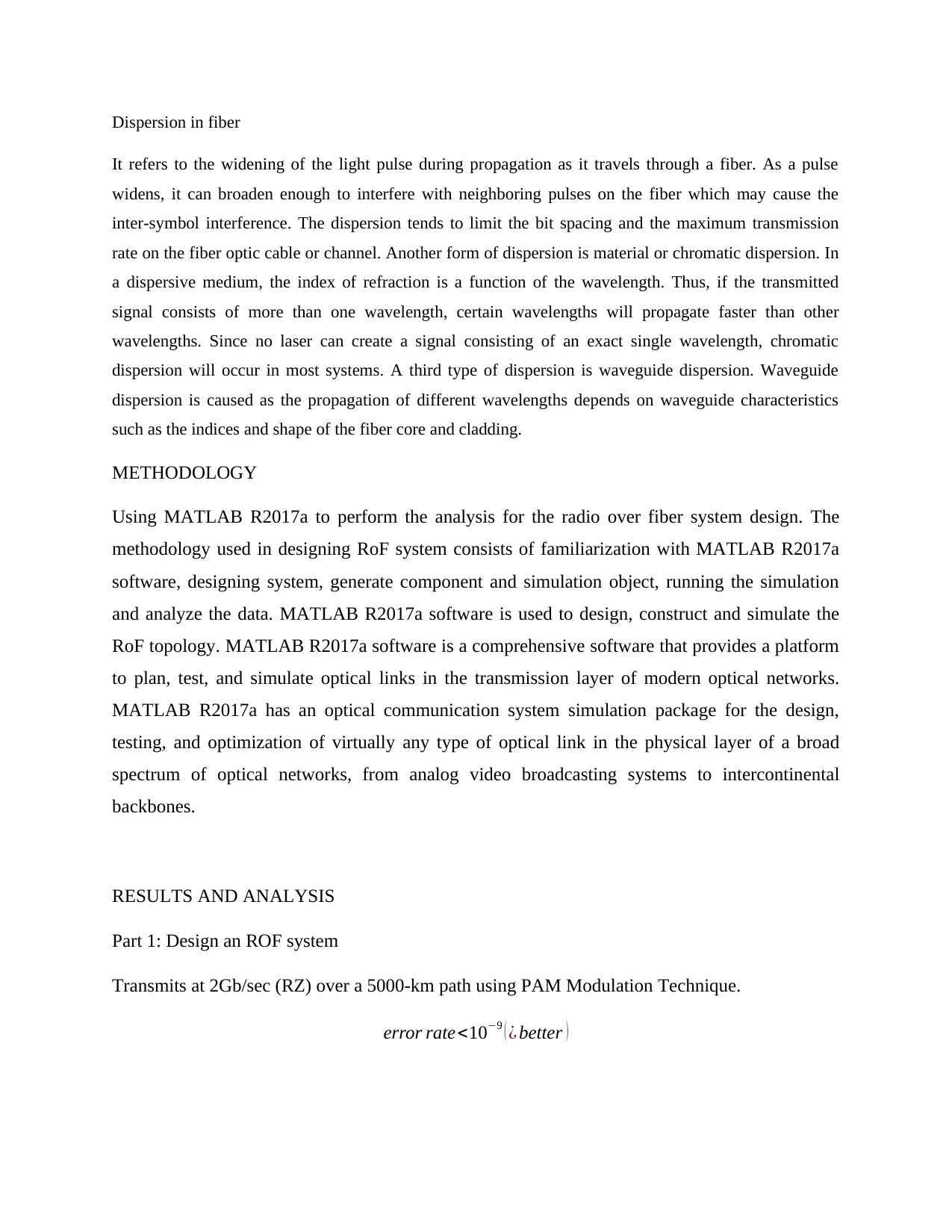
RESULTS AND ANALYSIS
Part 1: Design an ROF system
Transmits at 2Gb/sec (RZ) over a 5000-km path using PAM Modulation Technique.
error rate<10−9 ( ¿ better )
It refers to the widening of the light pulse during propagation as it travels through a fiber. As a pulse
widens, it can broaden enough to interfere with neighboring pulses on the fiber which may cause the
inter-symbol interference. The dispersion tends to limit the bit spacing and the maximum transmission
rate on the fiber optic cable or channel. Another form of dispersion is material or chromatic dispersion. In
a dispersive medium, the index of refraction is a function of the wavelength. Thus, if the transmitted
signal consists of more than one wavelength, certain wavelengths will propagate faster than other
wavelengths. Since no laser can create a signal consisting of an exact single wavelength, chromatic
dispersion will occur in most systems. A third type of dispersion is waveguide dispersion. Waveguide
dispersion is caused as the propagation of different wavelengths depends on waveguide characteristics
such as the indices and shape of the fiber core and cladding.
METHODOLOGY
Using MATLAB R2017a to perform the analysis for the radio over fiber system design. The
methodology used in designing RoF system consists of familiarization with MATLAB R2017a
software, designing system, generate component and simulation object, running the simulation
and analyze the data. MATLAB R2017a software is used to design, construct and simulate the
RoF topology. MATLAB R2017a software is a comprehensive software that provides a platform
to plan, test, and simulate optical links in the transmission layer of modern optical networks.
MATLAB R2017a has an optical communication system simulation package for the design,
testing, and optimization of virtually any type of optical link in the physical layer of a broad
spectrum of optical networks, from analog video broadcasting systems to intercontinental
backbones.
RESULTS AND ANALYSIS
Part 1: Design an ROF system
Transmits at 2Gb/sec (RZ) over a 5000-km path using PAM Modulation Technique.
error rate<10−9 ( ¿ better )
Paraphrase This Document
Need a fresh take? Get an instant paraphrase of this document with our AI Paraphraser
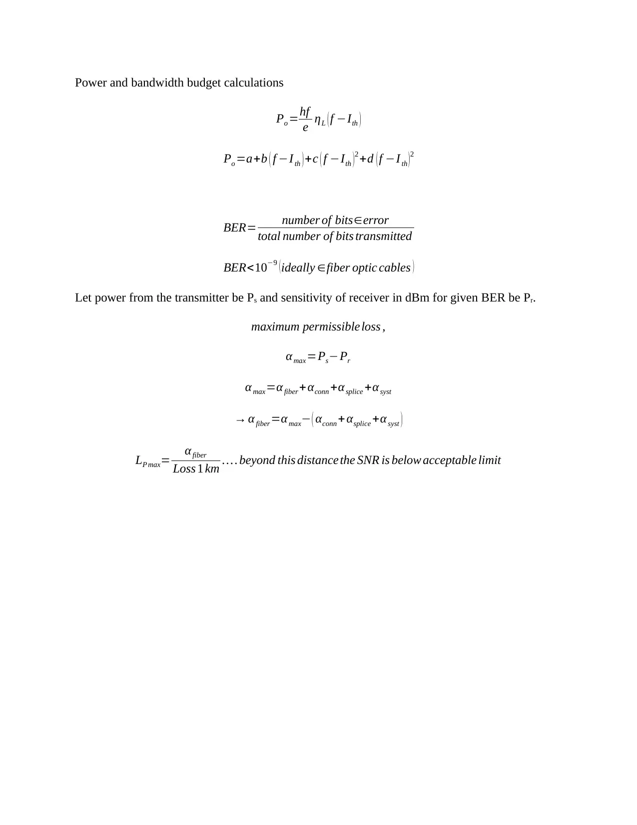
Power and bandwidth budget calculations
Po =hf
e ηL ( f −Ith )
Po =a+b ( f −Ith ) +c ( f −Ith )2 +d ( f −I th )2
BER= number of bits∈error
total number of bits transmitted
BER<10−9 (ideally ∈fiber optic cables )
Let power from the transmitter be Ps and sensitivity of receiver in dBm for given BER be Pr.
maximum permissible loss ,
α max =Ps−Pr
α max=α fiber + αconn +αsplice +αsyst
→ αfiber =αmax− ( αconn + αsplice +αsyst )
LP max= αfiber
Loss 1 km … . beyond this distance the SNR is below acceptable limit
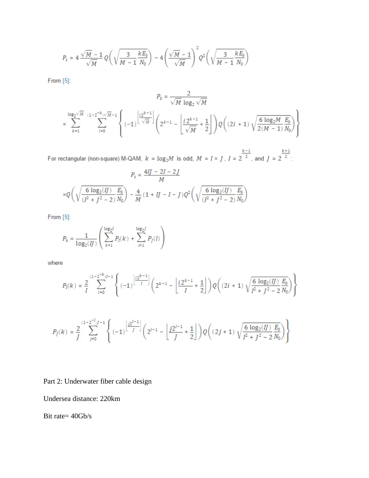
Part 2: Underwater fiber cable design
Undersea distance: 220km
Bit rate= 40Gb/s
Undersea distance: 220km
Bit rate= 40Gb/s
⊘ This is a preview!⊘
Do you want full access?
Subscribe today to unlock all pages.
Trusted by 1+ million students worldwide
1 out of 18

Your All-in-One AI-Powered Toolkit for Academic Success.
+13062052269
info@desklib.com
Available 24*7 on WhatsApp / Email
![[object Object]](/_next/static/media/star-bottom.7253800d.svg)
Unlock your academic potential
Copyright © 2020–2026 A2Z Services. All Rights Reserved. Developed and managed by ZUCOL.