Moscow State University: BIM Application in Energy Management Systems
VerifiedAdded on 2022/08/15
|6
|2579
|14
Report
AI Summary
This report, based on an IOP Conference Series paper, examines the application of Building Information Modeling (BIM) in the design of engineering systems for energy management, using a local wastewater treatment plant as a case study. The study outlines the stages of creating an information model from existing 2D documentation, highlighting the advantages of BIM, such as improved design accuracy, reduction of design errors, and the generation of correct specifications. The paper details the four main stages of model creation and discusses the benefits of using BIM, including improved operational efficiency, better control over resource consumption, and the ability to identify and rectify design flaws early in the process. The report emphasizes BIM's role in enhancing design quality, reducing errors, and optimizing energy use in urban infrastructure projects. The research also touches on the use of the model in the construction phase for forming estimates, planning, and creating 4D and 5D graphs. Overall, the report underscores the value of BIM in the design, construction, and operation of engineering facilities.

IOP Conference Series: Earth and Environmental Science
PAPER • OPEN ACCESS
Real application of BIM in the engineering system
design for energy management
To cite this article: Alexey Pelipenko and Elena Gogina 2017 IOP Conf. Ser.: Earth Environ. Sci. 90
012098
View the article online for updates and enhancements.
Related content
Introduction of Building Information
Modeling (BIM) Technologies in
Construction
M A Milyutina
-
Application of 6D Building Information
Model (6D BIM) for Business-storage
Building in Slovenia
Zoran Puko, Dražen Vincek, Andrej
Štrukelj et al.
-
A review of BIM (Building Information
Modeling) implementation in Indonesia
construction industry
Abdi Suryadinata Telaga
-
This content was downloaded from IP address 117.220.65.37 on 06/02/2020 at 15:53
Paraphrase This Document
Need a fresh take? Get an instant paraphrase of this document with our AI Paraphraser
1
Content from this work may be used under the terms of the Creative Commons Attribution 3.0 licence. Any further distribution
of this work must maintain attribution to the author(s) and the title of the work, journal citation and DOI.
Published under licence by IOP Publishing Ltd
1234567890
EMMFT 2017 IOP Publishing
IOP Conf. Series: Earth and Environmental Science 90 (2017) 012098doi:10.1088/1755-1315/90/1/012098
Real application of BIM in the engineering system design for
energy management
Alexey Pelipenko1 and Elena Gogina1
1Moscow State University of Civil Engineering, Yaroslavskoye shosse, 26, 129337,
Moscow, Russia
E-mail: aleksey23654@mail.ru
Abstract. In the article, the information modelling technology (BIM) that is gaining popularity
in Russia and in the world, is considered. Its growing relevance relates to many factors: first,
attention to this technology by the local and federal authorities; Secondly, with the desire to
improve the quality of design documentation, to obtain the correct volumes of materials and
equipment; Thirdly, with the tendency to create "smart" cities and, as a result, the rational use of
energy resources. Within the framework of this article, on an example of an urban infrastructure
object, the pros and cons of this technology were considered. As a facility, a local wastewater
treatment plant was chosen. The stages of creating an information model on the available
documentation are described: 4 main milestones that need to be implemented. In addition, further
possible ways of using the model are described. Presented are the pros and cons of using this
technology. Among the main advantages is the possibility of using this information model in the
operation of treatment plants and further obtaining actual data for monitoring the condition of
equipment and, therefore, controlling the consumable resources; At an early stage, a reduction
in the number of mutual intersections of engineering systems; Obtaining the correct
specifications. The results of the work described in the article can be used in the following areas:
utilities, energy management, design and construction.
1. Introduction
The improvement of water supply and sanitation systems is not only in the application of modern
operating technologies but also in the design process improvement allowing to reduce the number of
design errors. One of the ways to solve this problem is the information modelling technology developing
in Russia [1]. This technology has been rapidly developing with the support of major construction
market players. However, it should be noted that the use of BIM for engineering facilities such as sewage
treatment plants, pumping stations, water or wastewater treatment facilities is not reflected in the current
realities [2-4].
What is BIM? Its role in modern Russia.
The end of the XX - the early XXI centuries associated with rapid development of information
technologies were marked by the emergence of a fundamentally new approach in architectural and
construction design, which consisted in creation of a new building computer model containing all
information about the future object -Building Information Model (BIM). Despite the fact that the idea
was first formulated in 1975 by Professor of the Georgia Institute of Technology Chuck Eastman, it is
now when mass discussion and implementation of BIM technology in design and construction are
carried out [5,6].
Building Information Model (BIM) is:
2
1234567890
EMMFT 2017 IOP Publishing
IOP Conf. Series: Earth and Environmental Science 90 (2017) 012098doi:10.1088/1755-1315/90/1/012098
• Well-coordinated, coherent, and interrelated,
• Capable of being calculated and analysed,
• Geometrically linked,
• Suitable for computer use,
• Allowing necessary updates [7].
In other words, BIM is a numerical description and properly organized information about the object that
is used both at the design and construction stage of the building and during its operation and even
demolition [8,9].
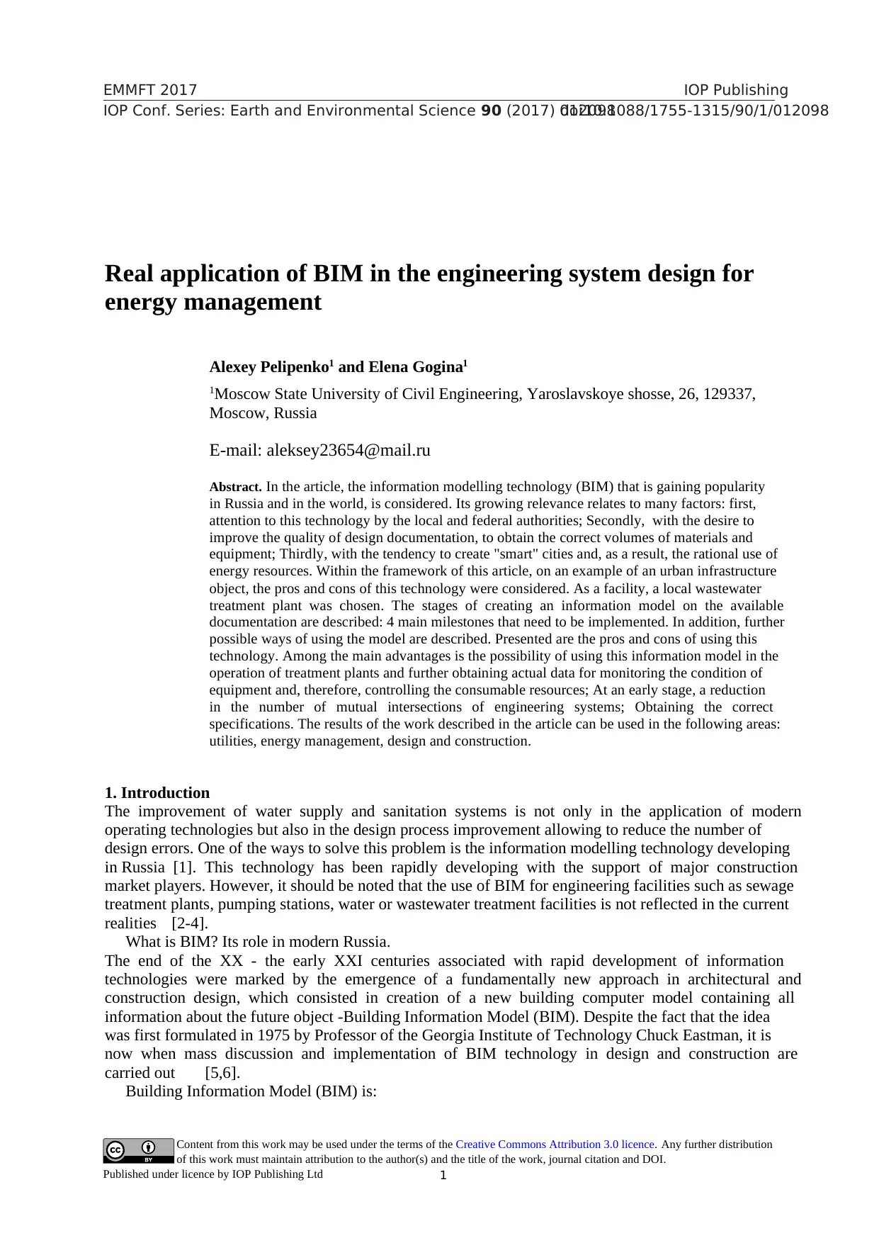
Unlike traditional computer-aided design systems creating geometric images, the result of building
information modelling is usually an object-oriented digital model of both the entire object and its
construction process. BIM layout is shown in figure. 1 [10].
Figure. 1. What BIM is.
2. Materials and Methods
Within the framework of this article, it was decided to build a model of a local wastewater treatment
plant based on the available PD stage documentation. It should be noted that the originally proposed
project was implemented in AutoCAD software package; this supposes the presence of 2D drawings in
DWG format.
When working with the BIM model, it is necessary to clearly organize it, designate a certain order
of actions, and strictly adhere to it so that the result meets expectations. That is why we identified several
stages being fundamental for further work.
The zero stage was designated as a preparatory one. As part of its implementation, the analysis of
existing documentation was conducted, design errors and ways of their elimination were found, a
procedure for creating intermediate models was planned, a list of used equipment and elements, their
sizes, and required parameters are approved. It was followed by the first stage.
The first stage implied the direct development of an architectural model, which further will be filled
with engineering networks and equipment. Since within the framework of our project we considered
local treatment facilities made of metal, the geometry of all structures included in the technological
scheme was created. These were a regulating tank, primary settler, pre-denitrifier, denitrifier, nitrifier,
secondary settler, post-treatment reactor, after-treatment filter, and aerobic sludge stabilizer. Work on
1234567890
EMMFT 2017 IOP Publishing
IOP Conf. Series: Earth and Environmental Science 90 (2017) 012098doi:10.1088/1755-1315/90/1/012098
• Well-coordinated, coherent, and interrelated,
• Capable of being calculated and analysed,
• Geometrically linked,
• Suitable for computer use,
• Allowing necessary updates [7].
In other words, BIM is a numerical description and properly organized information about the object that
is used both at the design and construction stage of the building and during its operation and even
demolition [8,9].
Unlike traditional computer-aided design systems creating geometric images, the result of building
information modelling is usually an object-oriented digital model of both the entire object and its
construction process. BIM layout is shown in figure. 1 [10].
Figure. 1. What BIM is.
2. Materials and Methods
Within the framework of this article, it was decided to build a model of a local wastewater treatment
plant based on the available PD stage documentation. It should be noted that the originally proposed
project was implemented in AutoCAD software package; this supposes the presence of 2D drawings in
DWG format.
When working with the BIM model, it is necessary to clearly organize it, designate a certain order
of actions, and strictly adhere to it so that the result meets expectations. That is why we identified several
stages being fundamental for further work.
The zero stage was designated as a preparatory one. As part of its implementation, the analysis of
existing documentation was conducted, design errors and ways of their elimination were found, a
procedure for creating intermediate models was planned, a list of used equipment and elements, their
sizes, and required parameters are approved. It was followed by the first stage.
The first stage implied the direct development of an architectural model, which further will be filled
with engineering networks and equipment. Since within the framework of our project we considered
local treatment facilities made of metal, the geometry of all structures included in the technological
scheme was created. These were a regulating tank, primary settler, pre-denitrifier, denitrifier, nitrifier,
secondary settler, post-treatment reactor, after-treatment filter, and aerobic sludge stabilizer. Work on
⊘ This is a preview!⊘
Do you want full access?
Subscribe today to unlock all pages.
Trusted by 1+ million students worldwide
3
1234567890
EMMFT 2017 IOP Publishing
IOP Conf. Series: Earth and Environmental Science 90 (2017) 012098doi:10.1088/1755-1315/90/1/012098
the first stage was simplified due to repetition of structures in the technological scheme and, as a
consequence, due to the lack of necessity to simulate them again.
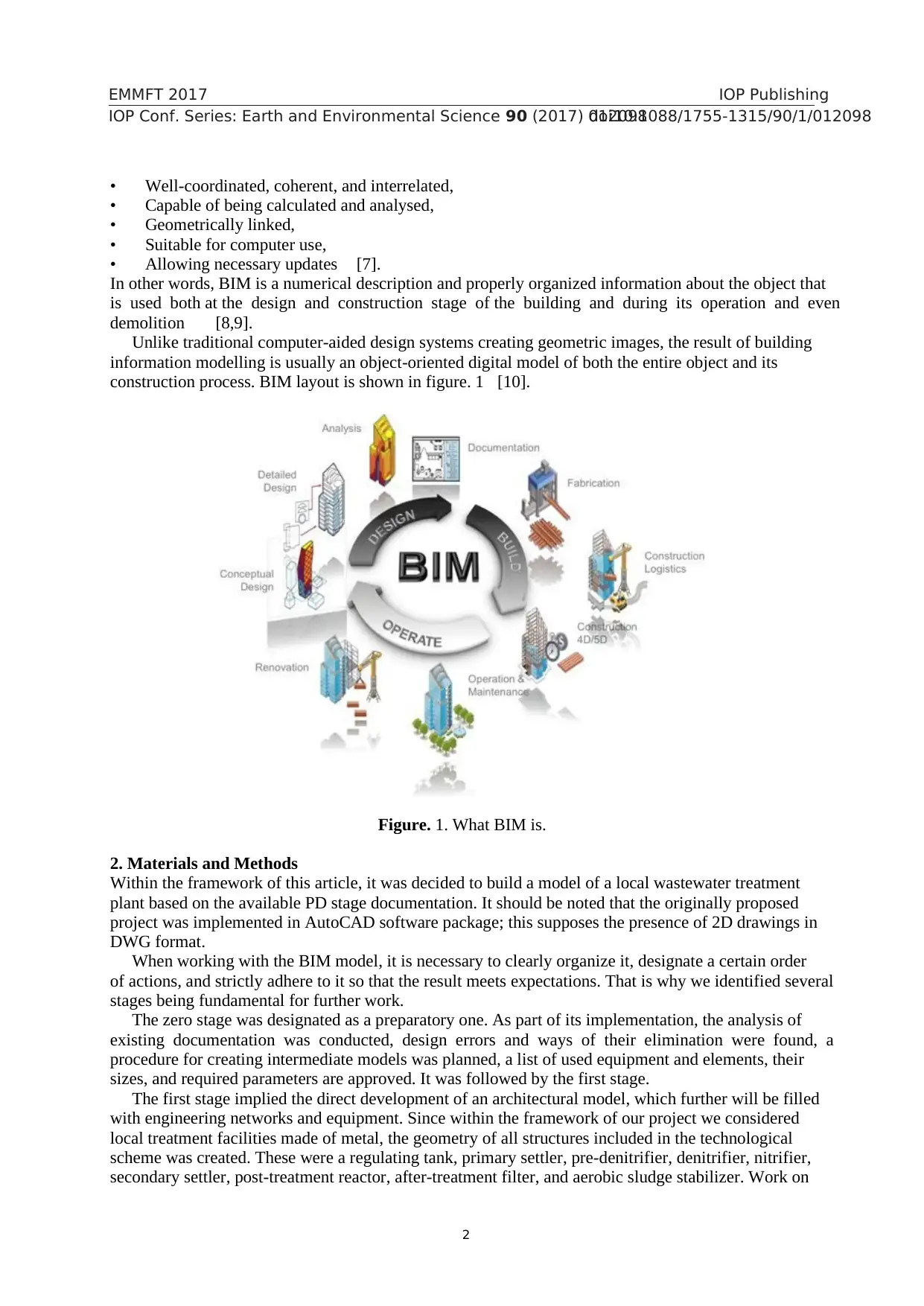
The second stage. For convenience of use, each model was created in a separate file. When the work
on architectural part development was completed, the structures were merged and 'blocked' in one
common file according to the adopted technological scheme for the sake of convenience in
implementation of projects of related specialties. The result is shown in figure. 2. This stage did not
cause any special difficulties and was in fact intermediate.
Figure. 2. The result of work at the stage 2.
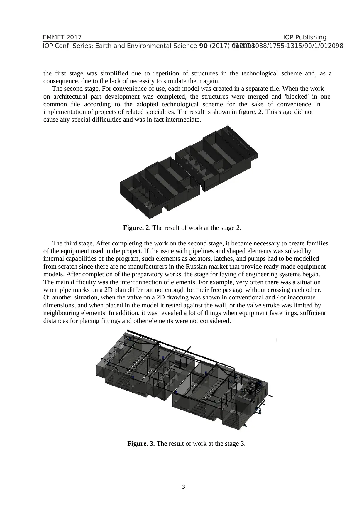
The third stage. After completing the work on the second stage, it became necessary to create families
of the equipment used in the project. If the issue with pipelines and shaped elements was solved by
internal capabilities of the program, such elements as aerators, latches, and pumps had to be modelled
from scratch since there are no manufacturers in the Russian market that provide ready-made equipment
models. After completion of the preparatory works, the stage for laying of engineering systems began.
The main difficulty was the interconnection of elements. For example, very often there was a situation
when pipe marks on a 2D plan differ but not enough for their free passage without crossing each other.
Or another situation, when the valve on a 2D drawing was shown in conventional and / or inaccurate
dimensions, and when placed in the model it rested against the wall, or the valve stroke was limited by
neighbouring elements. In addition, it was revealed a lot of things when equipment fastenings, sufficient
distances for placing fittings and other elements were not considered.
Figure. 3. The result of work at the stage 3.
1234567890
EMMFT 2017 IOP Publishing
IOP Conf. Series: Earth and Environmental Science 90 (2017) 012098doi:10.1088/1755-1315/90/1/012098
the first stage was simplified due to repetition of structures in the technological scheme and, as a
consequence, due to the lack of necessity to simulate them again.
The second stage. For convenience of use, each model was created in a separate file. When the work
on architectural part development was completed, the structures were merged and 'blocked' in one
common file according to the adopted technological scheme for the sake of convenience in
implementation of projects of related specialties. The result is shown in figure. 2. This stage did not
cause any special difficulties and was in fact intermediate.
Figure. 2. The result of work at the stage 2.
The third stage. After completing the work on the second stage, it became necessary to create families
of the equipment used in the project. If the issue with pipelines and shaped elements was solved by
internal capabilities of the program, such elements as aerators, latches, and pumps had to be modelled
from scratch since there are no manufacturers in the Russian market that provide ready-made equipment
models. After completion of the preparatory works, the stage for laying of engineering systems began.
The main difficulty was the interconnection of elements. For example, very often there was a situation
when pipe marks on a 2D plan differ but not enough for their free passage without crossing each other.
Or another situation, when the valve on a 2D drawing was shown in conventional and / or inaccurate
dimensions, and when placed in the model it rested against the wall, or the valve stroke was limited by
neighbouring elements. In addition, it was revealed a lot of things when equipment fastenings, sufficient
distances for placing fittings and other elements were not considered.
Figure. 3. The result of work at the stage 3.
Paraphrase This Document
Need a fresh take? Get an instant paraphrase of this document with our AI Paraphraser
4
1234567890
EMMFT 2017 IOP Publishing
IOP Conf. Series: Earth and Environmental Science 90 (2017) 012098doi:10.1088/1755-1315/90/1/012098
The fourth stage. After design of all adjacent sections, a visual model analysis was carried out, some
corrections were made, and visual materials for demonstration were prepared. In the future, it is planned
to execute a machine room model with the arrangement of large-sized equipment and the layout of
pipeline systems inside this building, and to perform siting of the station.
3. Results and discussions
As the performed work showed, the modern tendency towards the increased design speed cannot fail to
affect the number of made errors regardless of the control level by CPE and CPA organizations. It is a
poor quality of design documentation when designing in a classical way that became one of the
fundamental factors forcing the industry to start using BIM [11,12]. Most of the errors are related to
engineering systems and the interaction of several adjacent sections. Among the most frequent errors
that occur in design of engineering systems, the following points can be emphasized:
• Intersection of different systems. For example, sewage pipes with cable trays, main lines of water
supply systems with air ducts, etc.
• Difficulty in performing mounting works due to impossibility to correctly determine the location
of engineering systems. (Binding to unfinished structures).
• Passage of pipelines of engineering systems through the load-bearing structures and the necessity
of their location adjustment.
• Possibility to lose drawings and further difficulties with identification of the type of engineering
systems, and as a consequence - operation problems.
• Lack of space for correct system installation and use of incorrect connectors
• Limiting or impeding normal functioning of the elements
4. Conclusions
Based on the results of work with this model, we can identify several sectors where it could be useful
and describe a couple of use cases.
4.1. BIM for testing and design
3D model use allows not only to check the accuracy of design decisions but also to link them with other
sections, to check the correctness of location of adjacent equipment and elements. In addition, the receipt
of various specifications is greatly accelerated, which means the nullification of human factor and
complete elimination of errors in calculation.
The obtained model allowed to determine such drawbacks of the documentation created in 2D as:
• Absence of openings for utilities and pipelines
• Intersection of engineering systems
• Inconvenient places for maintenance and installation
• Overestimated number of pipelines and fittings
It is also worth highlighting one more possibility of the BIM model relating to the design. A designer
can very quickly change the material of pipes, equipment, change the overall dimensions of terminals,
and all these changes are automatically displayed not only in working form but also updated in all
working drawings containing this element. Thus, it eliminates another problem when the designer
changes, for example, one type of aerators to another in one form and forgets to change them in the
others. The result is an error and waste of time for project documentation adjustment [13].
4.2. BIM for operation
The application of BIM technologies has many advantages not only for the construction process,
reducing the number of design errors, but also significantly facilitates further operation of the facility or
structure. The main difference between BIM and simple 3D is that each element has a certain set of
properties, and not just some visual display. Hence, there are the following advantages:
• Using of real equipment with real dimensions and indicators by a designer
5
1234567890
EMMFT 2017 IOP Publishing
IOP Conf. Series: Earth and Environmental Science 90 (2017) 012098doi:10.1088/1755-1315/90/1/012098
• The operation service can use this model and see not only how any equipment is displayed but also
use its basic properties for repair or proper operation.
4.3. BIM for construction
The application of information modelling technology does not end solely in obtaining a fine 3D picture.
The resulting model can be used to form estimates, calendar and network planning, to create 4D and 5D
graphs (depicting the change of the model in time (4D) and change of the amount of spent resources,
including material ones to create a specific object) [14,15]. In addition, these models are used for
comparison between the model state according to the schedule and the current state of affairs on the
construction site.
5. Results
The result of this article is a proven coordinated model of a wastewater treatment plant; with a
constructive section that reflects the overall concept and with combined engineering section for
troubleshooting during design.
The key conclusions are that not only a designer but also the state should gradually implement this
technology. This, as it was said earlier, should stimulate the use of information modelling at all stages
of the object's life cycle.
References
[1] Information on http://concurator.ru/press_center/publications/?id_object=163
[2] Information on http://www.minstroyrf.ru/
[3] Information on http://isicad.ru/ru/articles.php?article_num=17535
[4] Information on http://isicad.ru/ru/articles.php?article_num=19084
[5] Information on http://bim-proektstroy.ru/?p=57М
[6] Kubba S 2017 Handbook of Green Building Design and Construction (Second Edition) 1 pp 227-
256
[7] Talapov V 2011 The Basis of BIM (Moscow: DMK Press) 410 pp
[8] Information on http://archspeech.com/article/otkuda-vzyalsya-bim-istoriya-virtual-noy-
arhitektury
[9] Alreshidi E Mourshed M and Rezgui Y 2017 Journal of Building Engineering 10 pp 89-101
[10] Information on https://dukelong.com/bim-building-information-modeling-quietly-changing
the-world/
[11] Liu Y Nederveen S and Hertlogh M International Journal of Project Management 35 pp 686-698
[12] Bouška R 2016 Procedia Engineering 164 pp 481-486
[13] Xu J 2017 Procedia Engineering 174 pp 600-610
[14] Boton C Kubicki S and Halin G 2015 Procedia Engineering 123 pp 59-67
[15] Smith P 2016 Procedia - Social and Behavioral Sciences 226 pp 193-200
⊘ This is a preview!⊘
Do you want full access?
Subscribe today to unlock all pages.
Trusted by 1+ million students worldwide
1 out of 6
Your All-in-One AI-Powered Toolkit for Academic Success.
+13062052269
info@desklib.com
Available 24*7 on WhatsApp / Email
![[object Object]](/_next/static/media/star-bottom.7253800d.svg)
Unlock your academic potential
Copyright © 2020–2026 A2Z Services. All Rights Reserved. Developed and managed by ZUCOL.