Deflection Analysis and Bending Moment of Reinforced Concrete Beams

Verified

Added on  2022/09/05

|30
|937
|47
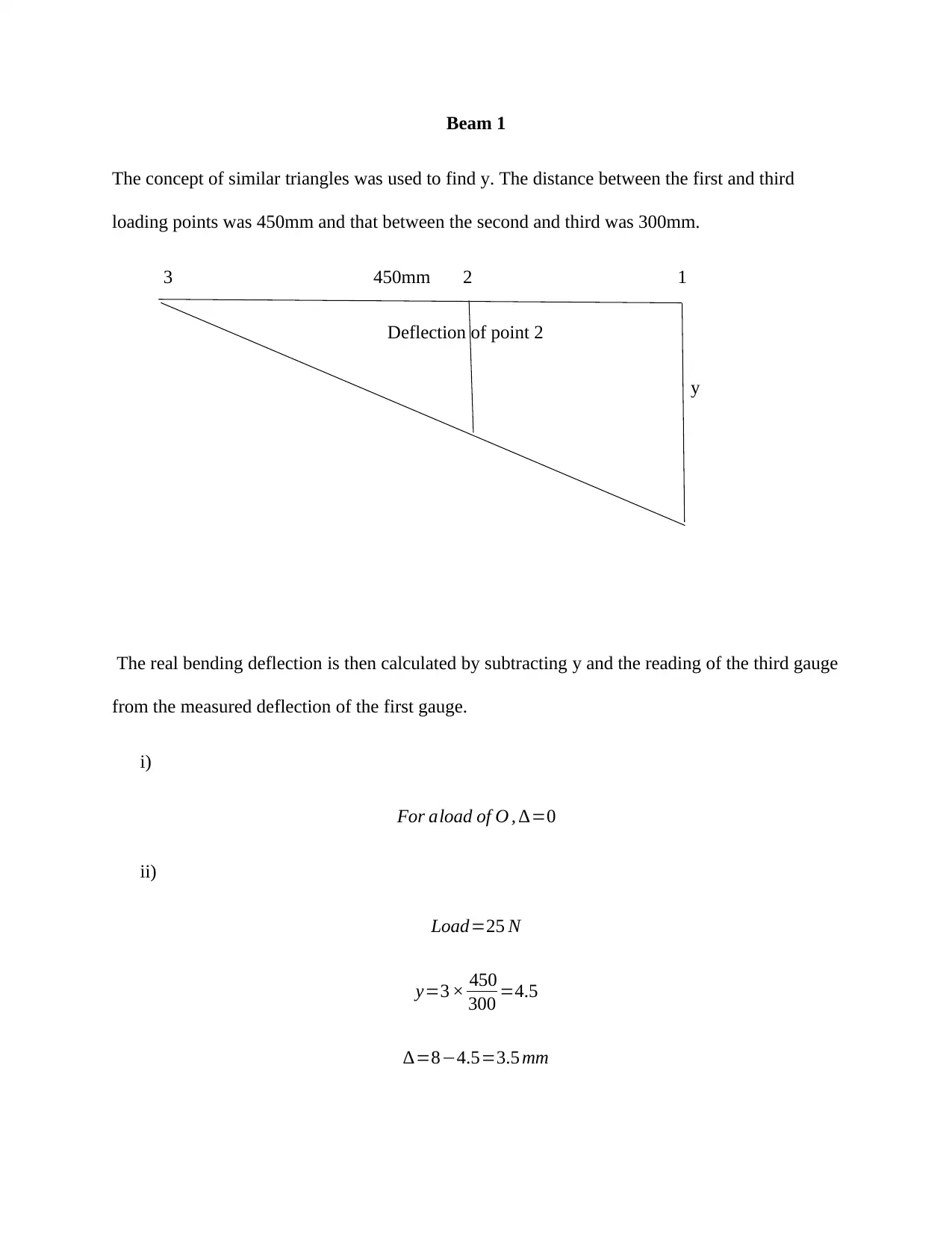
Practical Assignment
AI Summary
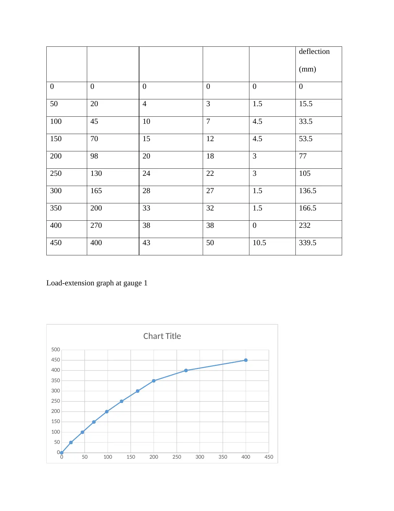
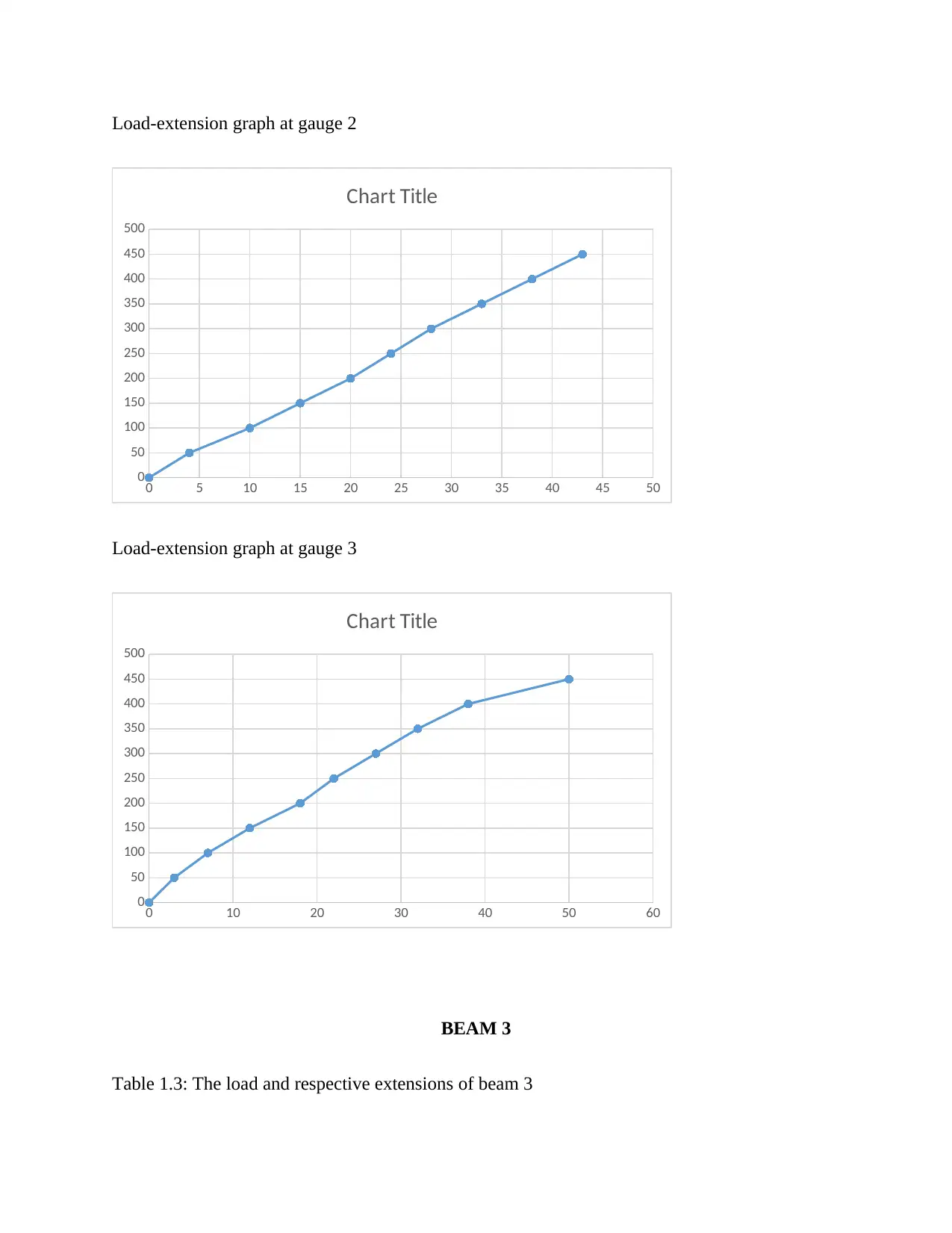
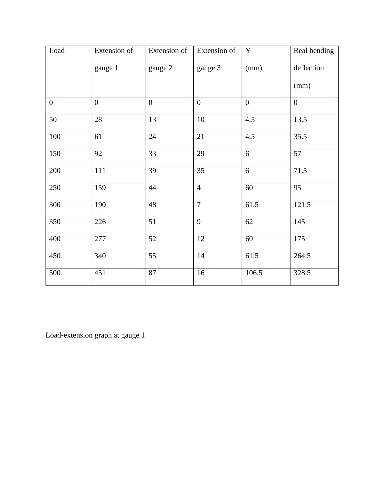
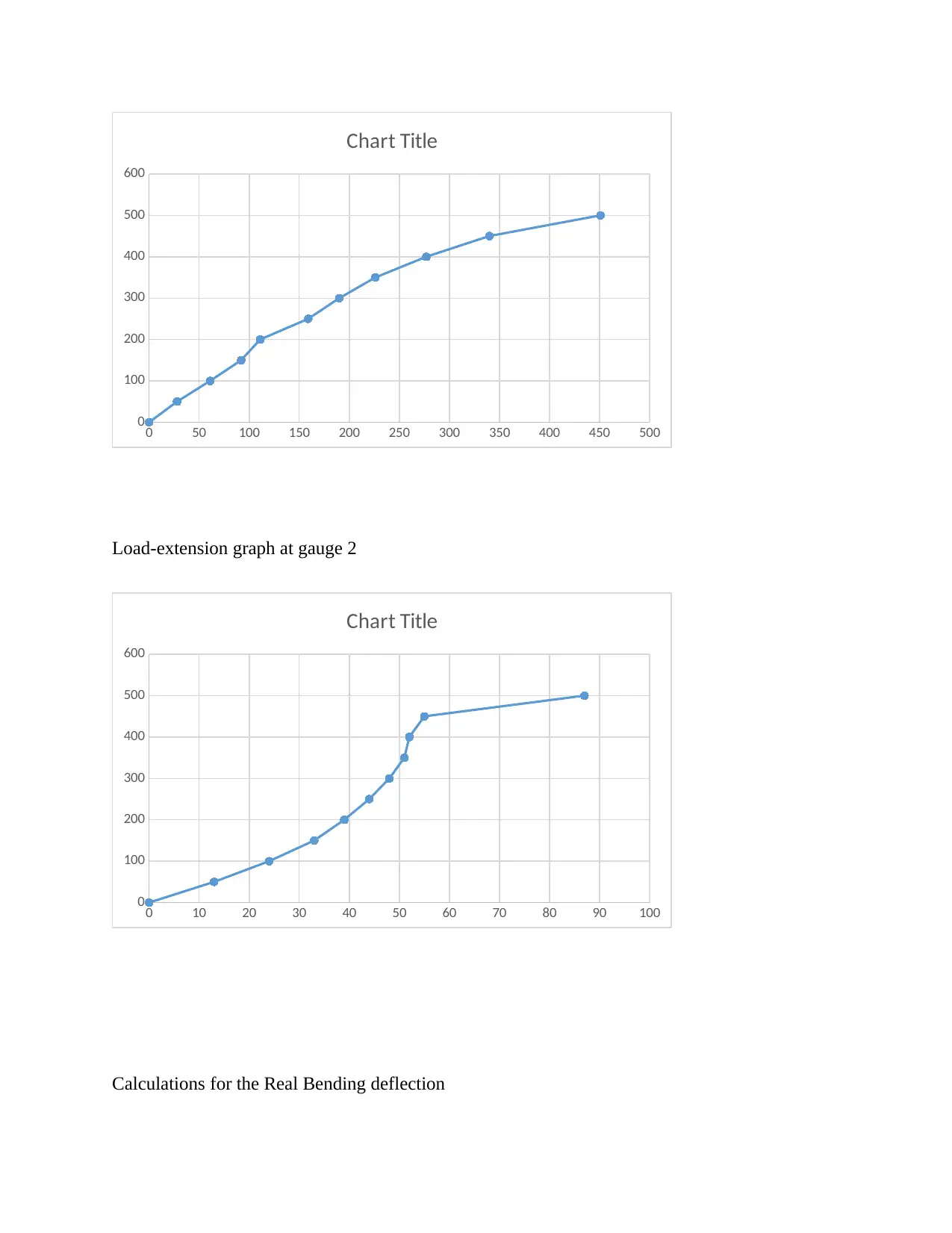
This assignment presents an experimental analysis of the load-extension characteristics and real bending deflection of reinforced concrete beams. The student has conducted tests on three beams (Beam 1, Beam 2, and Beam 3) with varying reinforcement configurations. The assignment includes detailed tables of load, gauge extensions, and calculated real bending deflections. Load-extension graphs for each gauge on each beam are also included. Calculations for real bending deflection are provided, utilizing the concept of similar triangles. Furthermore, the bending moment calculations are presented, taking into account the reaction force and distance from the gauge, with a calibration factor for the load incorporated. The analysis provides a comprehensive understanding of beam behavior under load, including the relationship between load, deflection, and bending moment.
Document Page
Load-Extension Graphs and Real Bending Deflection
Name of Student
Name of Professor
Date
tabler-icon-diamond-filled.svg

Paraphrase This Document

Need a fresh take? Get an instant paraphrase of this document with our AI Paraphraser
Document Page
BEAM 1
The extensions are not affected by the calibration errors because they were found through the
differences of the gauge readings.
Table 1.1: The load and respective extensions of beam 1
Load Gauge 1
extension
Gauge 2
extension
Gauge 3
extension
Y
(mm)
Real
Bending
Deflection
(mm)
0 0 0 0 0 0
25 8 3 0 4.5 3.5
78 30 7 2 7.5 20.5
100 39 10 5 7.5 26.5
125 77 13 8 7.5 61.5
150 99 15 9 9 81
175 125 18 11 10.5 103.5
200 138 19 14 7.5 116.5
225 148 21 15 9 124
250 174 22 17 7.5 149.5
275 215 25 19 9 187
300 238 26 21 7.5 209.5
325 278 27 22 7.5 248.5
350 317 29 24 7.5 285.5
Document Page
375 339 28 26 3 310
400 405 32 28 6 371
425 490 34 31 4.5 454.5
450 540 35 34 1.5 535.1
Load-extension graph of gauge 1
0 100 200 300 400 500 600
0
50
100
150
200
250
300
350
400
450
500
Chart Title
Load –extension graph of gauge 2
Document Page
0 5 10 15 20 25 30 35 40
0
50
100
150
200
250
300
350
400
450
500
Chart Title
Load-extension graph of gauge 3
0 5 10 15 20 25 30 35 40
0
50
100
150
200
250
300
350
400
450
500
Chart Title
BEAM 2
Table 1.2: The load and respective extensions of beam 2
Load Extension of
gauge 1
Extension of
gauge 2
Extension of
gauge 3
Y (mm) Real
bending
tabler-icon-diamond-filled.svg

Paraphrase This Document

Need a fresh take? Get an instant paraphrase of this document with our AI Paraphraser
Document Page
deflection
(mm)
0 0 0 0 0 0
50 20 4 3 1.5 15.5
100 45 10 7 4.5 33.5
150 70 15 12 4.5 53.5
200 98 20 18 3 77
250 130 24 22 3 105
300 165 28 27 1.5 136.5
350 200 33 32 1.5 166.5
400 270 38 38 0 232
450 400 43 50 10.5 339.5
Load-extension graph at gauge 1
0 50 100 150 200 250 300 350 400 450
0
50
100
150
200
250
300
350
400
450
500
Chart Title
Document Page
Load-extension graph at gauge 2
0 5 10 15 20 25 30 35 40 45 50
0
50
100
150
200
250
300
350
400
450
500
Chart Title
Load-extension graph at gauge 3
0 10 20 30 40 50 60
0
50
100
150
200
250
300
350
400
450
500
Chart Title
BEAM 3
Table 1.3: The load and respective extensions of beam 3
Document Page
Load Extension of
gauge 1
Extension of
gauge 2
Extension of
gauge 3
Y
(mm)
Real bending
deflection
(mm)
0 0 0 0 0 0
50 28 13 10 4.5 13.5
100 61 24 21 4.5 35.5
150 92 33 29 6 57
200 111 39 35 6 71.5
250 159 44 4 60 95
300 190 48 7 61.5 121.5
350 226 51 9 62 145
400 277 52 12 60 175
450 340 55 14 61.5 264.5
500 451 87 16 106.5 328.5
Load-extension graph at gauge 1
tabler-icon-diamond-filled.svg

Paraphrase This Document

Need a fresh take? Get an instant paraphrase of this document with our AI Paraphraser
Document Page
0 50 100 150 200 250 300 350 400 450 500
0
100
200
300
400
500
600
Chart Title
Load-extension graph at gauge 2
0 10 20 30 40 50 60 70 80 90 100
0
100
200
300
400
500
600
Chart Title
Calculations for the Real Bending deflection
Document Page
Beam 1
The concept of similar triangles was used to find y. The distance between the first and third
loading points was 450mm and that between the second and third was 300mm.
3 450mm 2 1
Deflection of point 2
y
The real bending deflection is then calculated by subtracting y and the reading of the third gauge
from the measured deflection of the first gauge.
i)
For aload of O , =0
ii)
Load=25 N
y=3 × 450
300 =4.5
=84.5=3.5 mm
Document Page
iii)
Load=78 N
y=5 × 450
300 =7.5
=30(7.5+2)=20.5 mm
iv)
Load=100 N
y=5 × 450
300 =7.5
=39(7.5+5)=26.5mm
v)
Load=125 N
y=5 × 450
300 =7.5
=77(7.5+ 8)=61.5 mm
vi)
Load=150 N
y=6× 450
300 =9
tabler-icon-diamond-filled.svg

Paraphrase This Document

Need a fresh take? Get an instant paraphrase of this document with our AI Paraphraser
Document Page
=99(9+9)=81 mm
vii)
Load=175 N
y=7 × 450
300 =10.5
=125(10.5+11)=103.5 mm
viii)
Load=200 N
y=5 × 450
300 =7.5
=138(7.5+14)=116.5 mm
ix)
Load=225 N
y=6× 450
300 =9
=148(9+15)=124 mm
x)
Load=250 N
y=5 × 450
300 =7.5
=174( 7.5+17)=149.5 mm
Document Page
xi)
Load=275 N
y=6× 450
300 =9
=215(9+ 19)=187 mm
xii)
Load=300 N
y=5 × 450
300 =7.5
=238(7.5+21)=209.5 mm
xiii)
Load=325 N
y=5 × 450
300 =7.5
=278(7.5+22)=248.5 mm
xiv)
Load=350 N
y=5 × 450
300 =7.5
=317(7.5+24)=285.5 mm
xv)
chevron_up_icon
1 out of 30
circle_padding
hide_on_mobile
zoom_out_icon
[object Object]