Data Analysis, Design, Implementation: Relational Database System
VerifiedAdded on 2024/05/20
|59
|6147
|338
Report
AI Summary
This report provides a comprehensive analysis and design of a relational database system, focusing on the Dominican College database. It begins by comparing different data models and database technologies, including hierarchical, network, relational, and object-oriented databases, and discusses their benefits and limitations. The report then details the design and implementation of a relational database system to meet specific requirements, including ER diagrams, table normalization, and SQL query implementation. Furthermore, it evaluates the use of manipulation and query tools for data extraction and includes testing and documentation of the implemented system, addressing verification, validation, and control mechanisms. User documentation is also provided to guide users in effectively utilizing the database. The report concludes with a discussion of test cases, user feedback, and the overall test plan to ensure the system's functionality and usability.

Data Analysis and Design
Paraphrase This Document
Need a fresh take? Get an instant paraphrase of this document with our AI Paraphraser
Table of Contents
Introduction.................................................................................................................................................6
LO1 Understand data models and database technologies............................................................................7
1.1 Critically compare different data models and schemas......................................................................7
1.2 Critically discuss the benefits and limitations of different database technologies............................13
1.3 Analyse different approaches to database design.............................................................................16
M1.........................................................................................................................................................17
LO2 Be able to design and implement relational database systems...........................................................18
2.1 design a relational database system to meet a given requirement....................................................18
ERD.......................................................................................................................................................18
2.2 Build a relational database system based on a prepared design........................................................22
2.3 Apply a range of database tools and techniques to enhance the user interface.................................25
M2.........................................................................................................................................................25
LO3 Be able to use manipulation and querying tools................................................................................26
3.1 Explain the benefits of using manipulation and query tools in a relational database system............26
3.2 Implement a query language into the relational database system that has been implemented..........26
3.3.Critically evaluates how meaningful data has been extracted through the use of query tools for the
given case study.....................................................................................................................................37
M3.........................................................................................................................................................40
LO4 Be able to test and document relational database systems.................................................................41
4.1 Critically reviews and tests the implemented relational database system.........................................41
4.2 Create documentation to support the implementation and testing of a relational database system...42
4.3 Create user documentation for a developed relational database system...........................................46
4.4 Explain how verification and validation has been addressed...........................................................53
4.5 Explain how control mechanisms have been used...........................................................................54
Conclusion.................................................................................................................................................56
References.................................................................................................................................................57
1
List of Figures
Figure 1: Hierarchical database...................................................................................................................6
Figure 2: Network Database........................................................................................................................7
Figure 3: Relational Database......................................................................................................................8
Figure 4: Object-oriented Database.............................................................................................................9
Figure 5: Database Schema with three levels............................................................................................10
Figure 6 Relationship diagram...................................................................................................................17
Figure 7 ER diagram.................................................................................................................................18
Figure 8 Conceptual diagram.....................................................................................................................19
Figure 9 Academic_Manager_Table..........................................................................................................21
Figure 10 Datasheet view of Academic_Manager_Table..........................................................................21
Figure 11 Admin_Table.............................................................................................................................21
Figure 12 Datasheet view of Admin_Table...............................................................................................21
Figure 13 Campus_Table...........................................................................................................................22
Figure 14 Datasheet view of Campus_Table.............................................................................................22
Figure 15 Course_Table............................................................................................................................22
Figure 16 Datasheet view of Course_Table...............................................................................................22
Figure 17 Lecturer_Table..........................................................................................................................22
Figure 18 Datasheet view of Lecturer_Table.............................................................................................23
Figure 19 Student_Table...........................................................................................................................23
Figure 20 Datasheet view of Student_Table..............................................................................................23
Figure 21 Units_Table...............................................................................................................................23
Figure 22 Datasheet view of Units_Table..................................................................................................24
Figure 23 SQL view of query 1.................................................................................................................25
Figure 24 Design view of query 1.............................................................................................................26
Figure 25 Output of query 1......................................................................................................................26
Figure 26 Report view of query 1..............................................................................................................27
Figure 27 SQL view of query 2.................................................................................................................27
Figure 28 Design view of query 2.............................................................................................................28
Figure 29 Output of query 2......................................................................................................................28
Figure 30 Report view of query 2..............................................................................................................29
Figure 31 SQL view of query 3.................................................................................................................29
Figure 32 Design view of query 3.............................................................................................................30
Figure 33 Output of query 3......................................................................................................................30
Figure 34 Report view of query 3..............................................................................................................31
Figure 35 SQL view of query 4.................................................................................................................31
Figure 36 Design view of query 4.............................................................................................................32
Figure 37 Output view of query 4..............................................................................................................32
Figure 38 Report view of query 4..............................................................................................................33
Figure 39 SQL view of query 5.................................................................................................................33
Figure 40 Design view of query 5.............................................................................................................33
2
⊘ This is a preview!⊘
Do you want full access?
Subscribe today to unlock all pages.
Trusted by 1+ million students worldwide
Figure 41 Output of query 5......................................................................................................................34
Figure 42 Report view of query 5..............................................................................................................34
Figure 43 SQL view of query 6.................................................................................................................34
Figure 44 Design view of query 6.............................................................................................................35
Figure 45 Output view of query 6..............................................................................................................35
Figure 46 Report view of query 6..............................................................................................................36
Figure 47 SQL view of manager query......................................................................................................36
Figure 48 Output of manager query...........................................................................................................36
Figure 49 SQL view of admin query.........................................................................................................37
Figure 50 Output of admin query..............................................................................................................37
Figure 51 SQL view of course query.........................................................................................................37
Figure 52 Output of course query..............................................................................................................38
Figure 53 SQL view of lecturer query.......................................................................................................38
Figure 54 Output of lecturer query............................................................................................................39
Figure 55 SQL view of student query........................................................................................................39
Figure 56 Output of student query.............................................................................................................39
Figure 57 Test case 1.................................................................................................................................42
Figure 58 Test case 2.................................................................................................................................42
Figure 59 Test case 3.................................................................................................................................43
Figure 60 Test case 4.................................................................................................................................43
Figure 61Test case 5..................................................................................................................................44
Figure 62 Academic manager form...........................................................................................................45
Figure 63 Report of academic manager form............................................................................................45
Figure 64 Admin form...............................................................................................................................46
Figure 65 Report of admin form................................................................................................................46
Figure 66 Campus form.............................................................................................................................47
Figure 67 Report of campus form..............................................................................................................47
Figure 68 Course form...............................................................................................................................47
Figure 69 Report of course form................................................................................................................48
Figure 70 Lecturer form............................................................................................................................48
Figure 71 Report of lecturer form..............................................................................................................49
Figure 72 Student form..............................................................................................................................49
Figure 73 Report of student form..............................................................................................................50
Figure 74 Units form.................................................................................................................................50
Figure 75 Report of units form..................................................................................................................51
Figure 76 Validation rule applied..............................................................................................................52
Figure 77 Control mechanism in admin table............................................................................................53
Figure 78 Control mechanism in admin table in student id........................................................................54
List of Tables
3
Paraphrase This Document
Need a fresh take? Get an instant paraphrase of this document with our AI Paraphraser

Table 11 NF...............................................................................................................................................19
Table 22 NF...............................................................................................................................................20
Table 3 Third normal form........................................................................................................................20
Table 4Feedback of different users............................................................................................................40
Table 5Table for test case..........................................................................................................................41
4
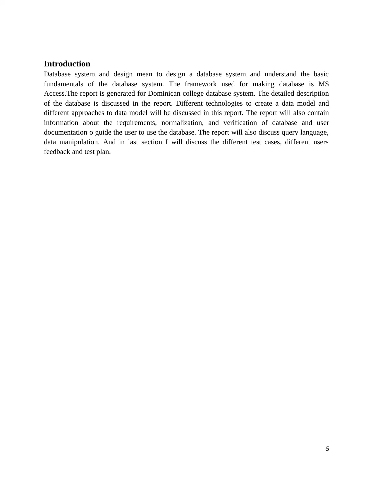
Introduction
Database system and design mean to design a database system and understand the basic
fundamentals of the database system. The framework used for making database is MS
Access.The report is generated for Dominican college database system. The detailed description
of the database is discussed in the report. Different technologies to create a data model and
different approaches to data model will be discussed in this report. The report will also contain
information about the requirements, normalization, and verification of database and user
documentation o guide the user to use the database. The report will also discuss query language,
data manipulation. And in last section I will discuss the different test cases, different users
feedback and test plan.
5
⊘ This is a preview!⊘
Do you want full access?
Subscribe today to unlock all pages.
Trusted by 1+ million students worldwide
LO1 Understand data models and database technologies
1.1 Critically compare different data models and schemas
DBMS is computer software that interacts with the application, end-user, and database for
collecting the data and their analysis. DBMS allowed the definition, update, creation, and
administration of databases. The database is a collection of information which managed by the
database administrator. There is a number of databases that are an object-oriented database,
network database, relational and hierarchical database.
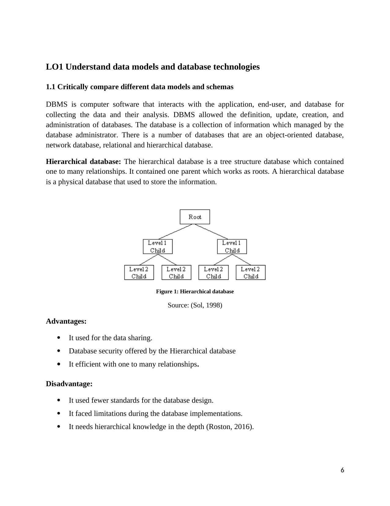
Hierarchical database: The hierarchical database is a tree structure database which contained
one to many relationships. It contained one parent which works as roots. A hierarchical database
is a physical database that used to store the information.
Figure 1: Hierarchical database
Source: (Sol, 1998)
Advantages:
It used for the data sharing.
Database security offered by the Hierarchical database
It efficient with one to many relationships.
Disadvantage:
It used fewer standards for the database design.
It faced limitations during the database implementations.
It needs hierarchical knowledge in the depth (Roston, 2016).
6
1.1 Critically compare different data models and schemas
DBMS is computer software that interacts with the application, end-user, and database for
collecting the data and their analysis. DBMS allowed the definition, update, creation, and
administration of databases. The database is a collection of information which managed by the
database administrator. There is a number of databases that are an object-oriented database,
network database, relational and hierarchical database.
Hierarchical database: The hierarchical database is a tree structure database which contained
one to many relationships. It contained one parent which works as roots. A hierarchical database
is a physical database that used to store the information.
Figure 1: Hierarchical database
Source: (Sol, 1998)
Advantages:
It used for the data sharing.
Database security offered by the Hierarchical database
It efficient with one to many relationships.
Disadvantage:
It used fewer standards for the database design.
It faced limitations during the database implementations.
It needs hierarchical knowledge in the depth (Roston, 2016).
6
Paraphrase This Document
Need a fresh take? Get an instant paraphrase of this document with our AI Paraphraser
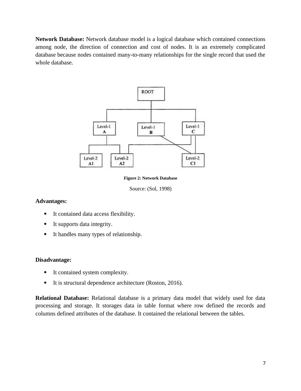
Network Database: Network database model is a logical database which contained connections
among node, the direction of connection and cost of nodes. It is an extremely complicated
database because nodes contained many-to-many relationships for the single record that used the
whole database.
Figure 2: Network Database
Source: (Sol, 1998)
Advantages:
It contained data access flexibility.
It supports data integrity.
It handles many types of relationship.
Disadvantage:
It contained system complexity.
It is structural dependence architecture (Roston, 2016).
Relational Database: Relational database is a primary data model that widely used for data
processing and storage. It storages data in table format where row defined the records and
columns defined attributes of the database. It contained the relational between the tables.
7
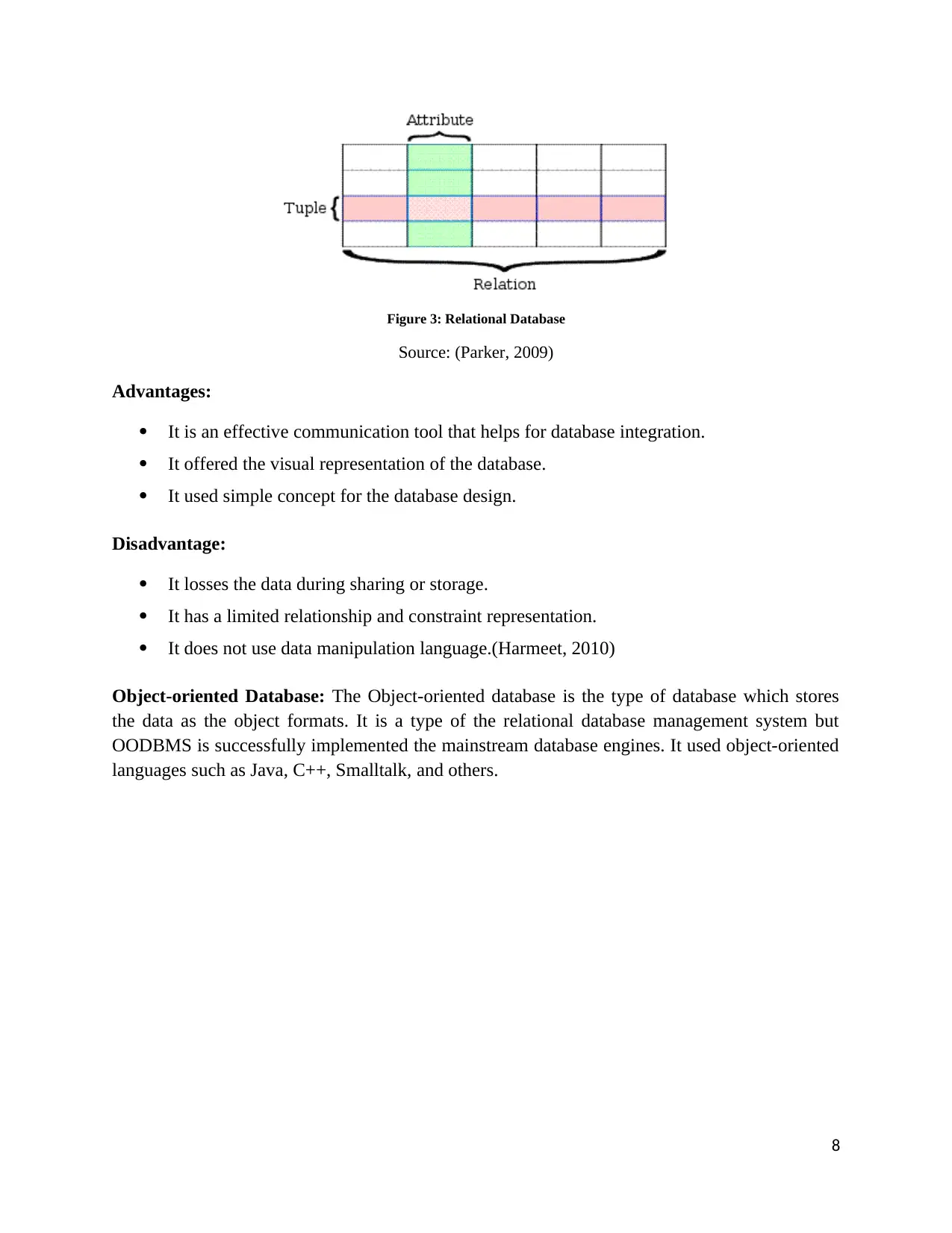
Figure 3: Relational Database
Source: (Parker, 2009)
Advantages:
It is an effective communication tool that helps for database integration.
It offered the visual representation of the database.
It used simple concept for the database design.
Disadvantage:
It losses the data during sharing or storage.
It has a limited relationship and constraint representation.
It does not use data manipulation language.(Harmeet, 2010)
Object-oriented Database: The Object-oriented database is the type of database which stores
the data as the object formats. It is a type of the relational database management system but
OODBMS is successfully implemented the mainstream database engines. It used object-oriented
languages such as Java, C++, Smalltalk, and others.
8
⊘ This is a preview!⊘
Do you want full access?
Subscribe today to unlock all pages.
Trusted by 1+ million students worldwide
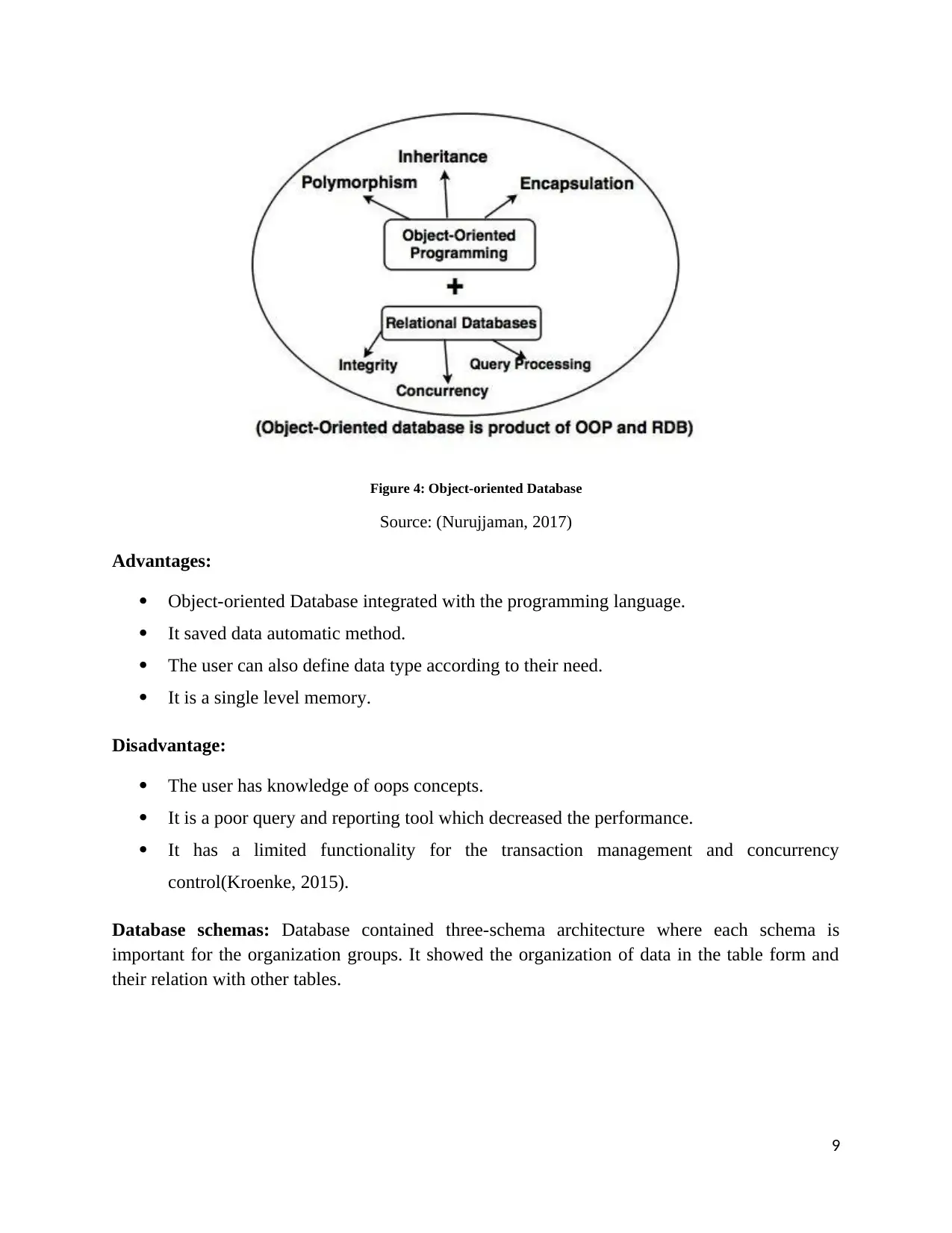
Figure 4: Object-oriented Database
Source: (Nurujjaman, 2017)
Advantages:
Object-oriented Database integrated with the programming language.
It saved data automatic method.
The user can also define data type according to their need.
It is a single level memory.
Disadvantage:
The user has knowledge of oops concepts.
It is a poor query and reporting tool which decreased the performance.
It has a limited functionality for the transaction management and concurrency
control(Kroenke, 2015).
Database schemas: Database contained three-schema architecture where each schema is
important for the organization groups. It showed the organization of data in the table form and
their relation with other tables.
9
Paraphrase This Document
Need a fresh take? Get an instant paraphrase of this document with our AI Paraphraser
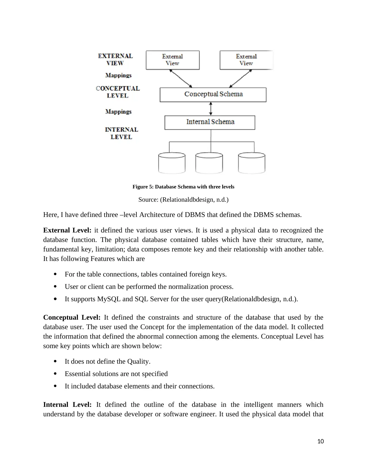
Figure 5: Database Schema with three levels
Source: (Relationaldbdesign, n.d.)
Here, I have defined three –level Architecture of DBMS that defined the DBMS schemas.
External Level: it defined the various user views. It is used a physical data to recognized the
database function. The physical database contained tables which have their structure, name,
fundamental key, limitation; data composes remote key and their relationship with another table.
It has following Features which are
For the table connections, tables contained foreign keys.
User or client can be performed the normalization process.
It supports MySQL and SQL Server for the user query(Relationaldbdesign, n.d.).
Conceptual Level: It defined the constraints and structure of the database that used by the
database user. The user used the Concept for the implementation of the data model. It collected
the information that defined the abnormal connection among the elements. Conceptual Level has
some key points which are shown below:
It does not define the Quality.
Essential solutions are not specified
It included database elements and their connections.
Internal Level: It defined the outline of the database in the intelligent manners which
understand by the database developer or software engineer. It used the physical data model that
10
described access paths and physical storage structures. It contained following Characteristics
which are
Contained elements and their relationships.
It explained each element characteristic.
This level contained database normalization.
Essential solutions are specified (Relationaldbdesign, n.d.)
11
which are
Contained elements and their relationships.
It explained each element characteristic.
This level contained database normalization.
Essential solutions are specified (Relationaldbdesign, n.d.)
11
⊘ This is a preview!⊘
Do you want full access?
Subscribe today to unlock all pages.
Trusted by 1+ million students worldwide
1 out of 59
Related Documents


Your All-in-One AI-Powered Toolkit for Academic Success.
+13062052269
info@desklib.com
Available 24*7 on WhatsApp / Email
![[object Object]](/_next/static/media/star-bottom.7253800d.svg)
Unlock your academic potential
Copyright © 2020–2026 A2Z Services. All Rights Reserved. Developed and managed by ZUCOL.