Relational Database System Design, Implementation and Testing Project
VerifiedAdded on 2024/05/21
|41
|4497
|118
Project
AI Summary
This project report outlines the design, development, and testing of a relational database system for ULKOM LTD, a company with extensive experience in electronic database systems. The database is designed to meet specific company requirements, facilitating efficient data updates and ensuring data reliability and security. The report details the design process, including the use of ER diagrams and data normalization techniques (1NF, 2NF, 3NF) to reduce data redundancy and ensure data integrity. The implementation phase involves creating database tables in MS SQL Server, defining relationships between tables, and implementing data validation rules. The report also includes a comprehensive test plan with various test cases to validate the database's functionality and data integrity. User and technical documentation are provided, along with example queries for data retrieval and management information generation. This project ensures a fully functional and well-documented database system.
Database Assignment
Paraphrase This Document
Need a fresh take? Get an instant paraphrase of this document with our AI Paraphraser
Contents
Introduction...............................................................................................................................4
LO1 Use an appropriate design tool to design a relational database system for a substantial
problem......................................................................................................................................5
P1 Design a relational database system using appropriate design tools and techniques.....5
M1 Produce a comprehensive design for a fully functional system......................................8
LO2 Develop a fully functional relational database system, based on an existing system
design:......................................................................................................................................14
P2 Develop and implement a fully functional database system using MS SQL Server:.......14
M2 Implement a fully functional database system..............................................................19
P3 Produce a query language, with queries across multiple tables produced earlier:........20
M3 Produce appropriate management information...........................................................23
LO3 Test the system against user and system requirements:.................................................24
P4 Create a test plan to test the database:..........................................................................24
M4. Assess the effectiveness of the testing.........................................................................26
LO4 User and Technical Documentation:................................................................................27
P5 Produce technical and user documentation...................................................................27
M5: Produce fully functional system....................................................................................35
Conclusion................................................................................................................................36
References................................................................................................................................37
1
List of figures
Figure 1 ER Diagram...................................................................................................................8
Figure 2 Unormalised Form......................................................................................................11
Figure 3 1 NF............................................................................................................................12
Figure 4 2 NF............................................................................................................................12
Figure 5 3 NF............................................................................................................................13
Figure 6 animal table................................................................................................................14
Figure 7 animal data information view....................................................................................15
Figure 8 Appointment table.....................................................................................................15
Figure 9 appointment data information view..........................................................................15
Figure 10 branch table.............................................................................................................16
Figure 11 branch data information view..................................................................................16
Figure 12 owner table..............................................................................................................16
Figure 13 owner data information view..................................................................................17
Figure 14 staff table.................................................................................................................17
Figure 15 staff data information view......................................................................................17
Figure 16 prescription table.....................................................................................................18
Figure 17 prescription data information view.........................................................................18
Figure 18 bill table....................................................................................................................18
Figure 19 bill data information view........................................................................................19
Figure 20 query output 1.........................................................................................................20
Figure 21 query output 2.........................................................................................................21
Figure 22 query output 3.........................................................................................................22
Figure 23 query output 4.........................................................................................................22
Figure 24query output 5..........................................................................................................23
Figure 25 query output 6.........................................................................................................23
Figure 26 test case 1.................................................................................................................25
Figure 27 test case 2.................................................................................................................25
Figure 28 test case 3.................................................................................................................25
Figure 29 test case 4.................................................................................................................26
Figure 30 test case 5.................................................................................................................26
2
⊘ This is a preview!⊘
Do you want full access?
Subscribe today to unlock all pages.
Trusted by 1+ million students worldwide
Figure 31 test case 6.................................................................................................................26
Figure 32 staff table.................................................................................................................27
Figure 33 branch table.............................................................................................................27
Figure 34 animal table..............................................................................................................28
Figure 35 owner table..............................................................................................................28
Figure 36 appointment table...................................................................................................28
Figure 37 prescription table.....................................................................................................29
Figure 38 bill table....................................................................................................................29
Figure 39 query 1.....................................................................................................................29
Figure 40 query 2.....................................................................................................................30
Figure 41 query 3.....................................................................................................................30
Figure 42 query 4.....................................................................................................................30
Figure 43 query 5.....................................................................................................................31
Figure 44 query 6.....................................................................................................................31
Figure 45 Relation diagram for VET solution...........................................................................32
Figure 46 animal table design..................................................................................................32
Figure 47 appointment table design........................................................................................33
Figure 48 bill table design........................................................................................................33
Figure 49 staff table design......................................................................................................33
Figure 50 owner table design...................................................................................................34
Figure 51 branch table design..................................................................................................34
Figure 52 prescription table design..........................................................................................34
Figure 53 functional dependency diagram..............................................................................35
List of tables
Table 1 data dictionary table.....................................................................................................7
Table 2 test case table..............................................................................................................18
3
Paraphrase This Document
Need a fresh take? Get an instant paraphrase of this document with our AI Paraphraser
Introduction
In the project report, it is developed and designed for the database management for a
system which is provided by a company ULKOM LTD in Cambridgeshire who has many years
of experience in an electronic database system. This database is designed to meet company
requirements and helps to their staff for ease of system data updation and provide the
reliable and secure database.
The database management system after implementation successfully, send for testing and
validating data information using various test cases and provided all information in this
report with examples.
4
LO1 Use an appropriate design tool to design a relational database system for
a substantial problem
P1 Design a relational database system using appropriate design tools and
techniques.
Roles and specification of VET solution Database System:
An arrangement of VET solution Database is utilized to oversee entire information inside an
organization by putting away tremendous measures of information. The programming
application is utilizing relational database tables. It diminishes information repetition and
presents information in a persuading way that aides in proficient basic leadership. It
enhances the execution of a framework and gives progress worked in examination
functionalities. The VET solution database tables also provide help to maintain data
information by storing in database warehouse to fetch anytime through application level.
Relational Database tool and some techniques:
Relational Database is the most widely recognized kind of DBMS. In this, information is
stored in the form of tables. Application software utilized for arranging information in tables
is MS SQL Server. It is otherwise called Standard Query Language which is known as SQL
(sequel). Relational databases frequently drive the organization basic and web-empowered
applications basic for making progress in an exceptionally aggressive market. It is designed
to convey the basis for building and works with the relational data parts and empowering to
create and utilize relational databases in the environment.
Logical Design for Relational Database:-
A logical data model is needed in beginning to layout a VET arrangement physical database.
What's more, the consistent information show ends up out of a reasonable information
display. Moreover, different kind of information show begins with the preparation of
information display. The logical data model stage formalizes the entities, or attributes, and
their objects. Another essential undertaking of logical data modeling is to guarantee that the
model entities are adjusted by attributes that extraordinarily relate to them. No attribute
5
⊘ This is a preview!⊘
Do you want full access?
Subscribe today to unlock all pages.
Trusted by 1+ million students worldwide
ought to show up in an element unless it depicts the uniqueness identifier for the entity
which is the primary key.
ER- Diagram
These are entity relationship diagrams which are used for pictorial representation or
understanding of data information shared among different entities. A design function allows
admin to see the relationships between various entities known as ER diagram.
Entity
An object is a part of entity exists in the database. It doesn't have to do anything; it
essentially needs to exist. In database association, an element can be an alone thing,
individual, place, or question. Data can be secured about such substance.
Attribute
An attribute characterizes the data about the entity that should be put away. In the
database that the entity is a worker, attributes could incorporate name, person ID,
wellbeing design enlistment, and work area. An entity will have at least zero attributes, and
every one of those attributes applies just to that entity.
Relationship
A relationship describes the relation between tables or entities in a database and it is
represented by diamond shape and it has many types.
Data Elements
Data elements are the data information of entities such as its attributes in a database which
are specified by its data types.
Data Types:
The data type is used to define what type of information is storing in entities such as
integer, float, character, string or more. Basically, it defines the type of variable which is
used in the database.
Indexing
6
Paraphrase This Document
Need a fresh take? Get an instant paraphrase of this document with our AI Paraphraser
Indexing is used for finding the location of data stored in the database by providing key to
them or some pointers or address.
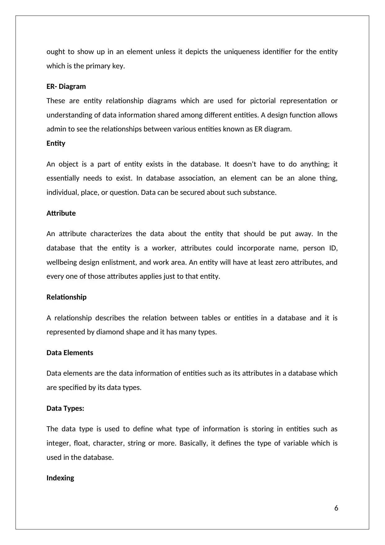
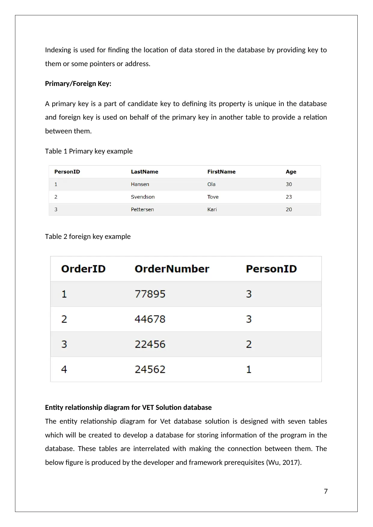
Primary/Foreign Key:
A primary key is a part of candidate key to defining its property is unique in the database
and foreign key is used on behalf of the primary key in another table to provide a relation
between them.
Table 1 Primary key example
Table 2 foreign key example
Entity relationship diagram for VET Solution database
The entity relationship diagram for Vet database solution is designed with seven tables
which will be created to develop a database for storing information of the program in the
database. These tables are interrelated with making the connection between them. The
below figure is produced by the developer and framework prerequisites (Wu, 2017).
7
them or some pointers or address.
Primary/Foreign Key:
A primary key is a part of candidate key to defining its property is unique in the database
and foreign key is used on behalf of the primary key in another table to provide a relation
between them.
Table 1 Primary key example
Table 2 foreign key example
Entity relationship diagram for VET Solution database
The entity relationship diagram for Vet database solution is designed with seven tables
which will be created to develop a database for storing information of the program in the
database. These tables are interrelated with making the connection between them. The
below figure is produced by the developer and framework prerequisites (Wu, 2017).
7
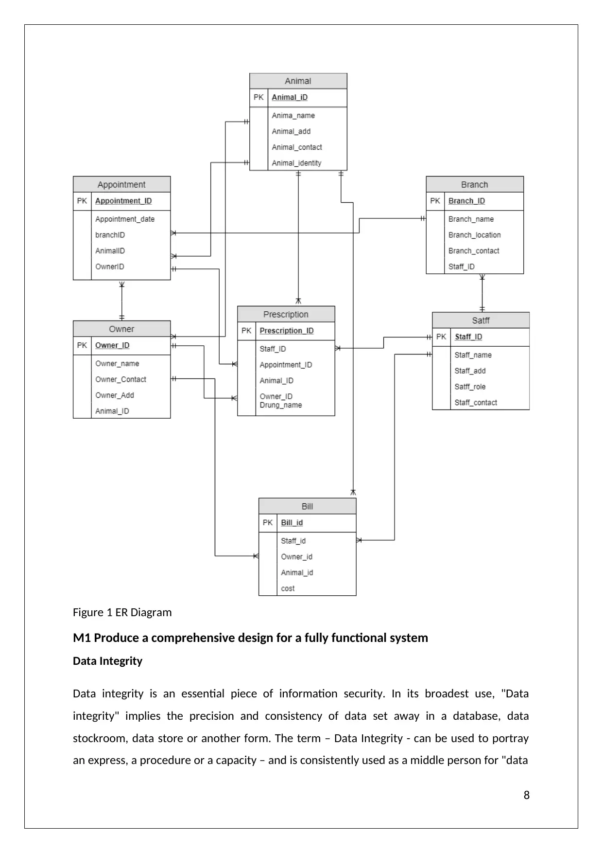
Figure 1 ER Diagram
M1 Produce a comprehensive design for a fully functional system
Data Integrity
Data integrity is an essential piece of information security. In its broadest use, "Data
integrity" implies the precision and consistency of data set away in a database, data
stockroom, data store or another form. The term – Data Integrity - can be used to portray
an express, a procedure or a capacity – and is consistently used as a middle person for "data
8
⊘ This is a preview!⊘
Do you want full access?
Subscribe today to unlock all pages.
Trusted by 1+ million students worldwide
quality". Data with "integrity" is said to have an aggregate or whole structure. Data regards
are organized by an information display and additionally information writes.
Data Validation
When utilizing SQL, validation of data information is the part of a VET solution database that
keeps information steady. The key factors in data integrity are constraints, referential
integrity and the delete and update-alternatives. The fundamental sorts of requirements in
SQL are check, unique, not null, and primary constraints. Check limitations are utilized to
verify that an announcement about the information is valid for all lines in a table. The
unique constraint guarantees that no two lines have similar qualities in their sections. The
not null constraint is put on a segment and expresses that information is required in that
section.
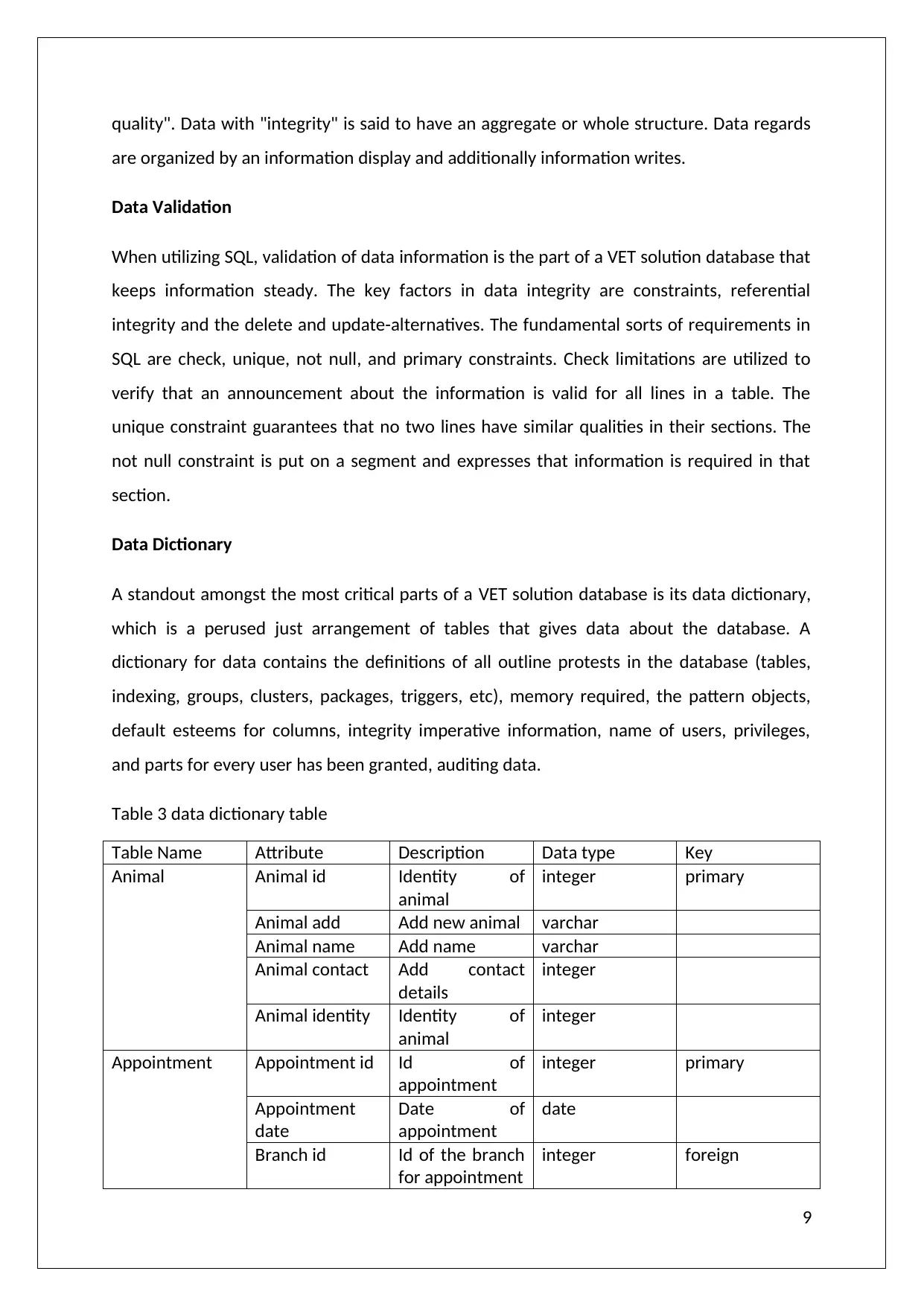
Data Dictionary
A standout amongst the most critical parts of a VET solution database is its data dictionary,
which is a perused just arrangement of tables that gives data about the database. A
dictionary for data contains the definitions of all outline protests in the database (tables,
indexing, groups, clusters, packages, triggers, etc), memory required, the pattern objects,
default esteems for columns, integrity imperative information, name of users, privileges,
and parts for every user has been granted, auditing data.
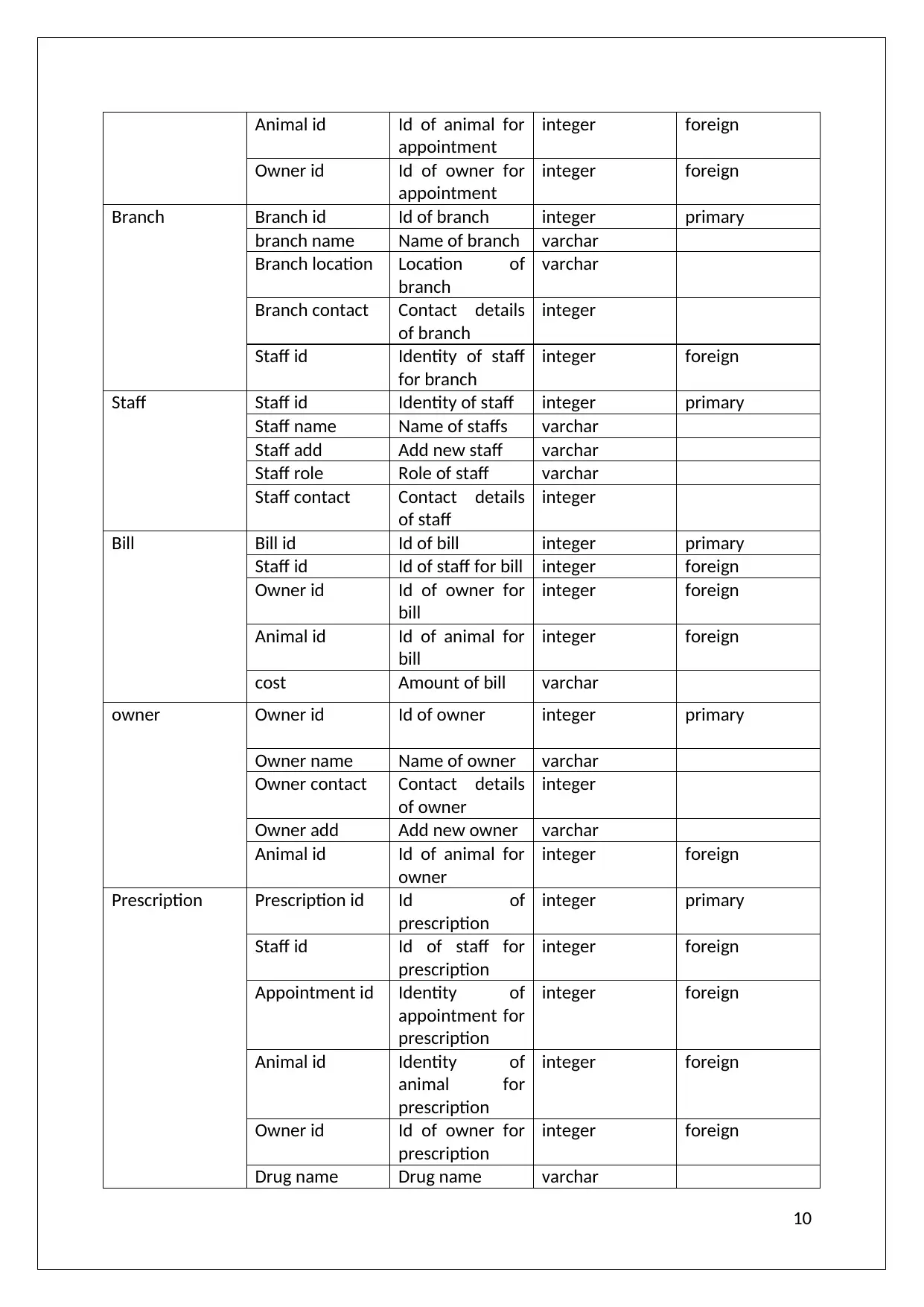
Table 3 data dictionary table
Table Name Attribute Description Data type Key
Animal Animal id Identity of
animal
integer primary
Animal add Add new animal varchar
Animal name Add name varchar
Animal contact Add contact
details
integer
Animal identity Identity of
animal
integer
Appointment Appointment id Id of
appointment
integer primary
Appointment
date
Date of
appointment
date
Branch id Id of the branch
for appointment
integer foreign
9
are organized by an information display and additionally information writes.
Data Validation
When utilizing SQL, validation of data information is the part of a VET solution database that
keeps information steady. The key factors in data integrity are constraints, referential
integrity and the delete and update-alternatives. The fundamental sorts of requirements in
SQL are check, unique, not null, and primary constraints. Check limitations are utilized to
verify that an announcement about the information is valid for all lines in a table. The
unique constraint guarantees that no two lines have similar qualities in their sections. The
not null constraint is put on a segment and expresses that information is required in that
section.
Data Dictionary
A standout amongst the most critical parts of a VET solution database is its data dictionary,
which is a perused just arrangement of tables that gives data about the database. A
dictionary for data contains the definitions of all outline protests in the database (tables,
indexing, groups, clusters, packages, triggers, etc), memory required, the pattern objects,
default esteems for columns, integrity imperative information, name of users, privileges,
and parts for every user has been granted, auditing data.
Table 3 data dictionary table
Table Name Attribute Description Data type Key
Animal Animal id Identity of
animal
integer primary
Animal add Add new animal varchar
Animal name Add name varchar
Animal contact Add contact
details
integer
Animal identity Identity of
animal
integer
Appointment Appointment id Id of
appointment
integer primary
Appointment
date
Date of
appointment
date
Branch id Id of the branch
for appointment
integer foreign
9
Paraphrase This Document
Need a fresh take? Get an instant paraphrase of this document with our AI Paraphraser
Animal id Id of animal for
appointment
integer foreign
Owner id Id of owner for
appointment
integer foreign
Branch Branch id Id of branch integer primary
branch name Name of branch varchar
Branch location Location of
branch
varchar
Branch contact Contact details
of branch
integer
Staff id Identity of staff
for branch
integer foreign
Staff Staff id Identity of staff integer primary
Staff name Name of staffs varchar
Staff add Add new staff varchar
Staff role Role of staff varchar
Staff contact Contact details
of staff
integer
Bill Bill id Id of bill integer primary
Staff id Id of staff for bill integer foreign
Owner id Id of owner for
bill
integer foreign
Animal id Id of animal for
bill
integer foreign
cost Amount of bill varchar
owner Owner id Id of owner integer primary
Owner name Name of owner varchar
Owner contact Contact details
of owner
integer
Owner add Add new owner varchar
Animal id Id of animal for
owner
integer foreign
Prescription Prescription id Id of
prescription
integer primary
Staff id Id of staff for
prescription
integer foreign
Appointment id Identity of
appointment for
prescription
integer foreign
Animal id Identity of
animal for
prescription
integer foreign
Owner id Id of owner for
prescription
integer foreign
Drug name Drug name varchar
10
appointment
integer foreign
Owner id Id of owner for
appointment
integer foreign
Branch Branch id Id of branch integer primary
branch name Name of branch varchar
Branch location Location of
branch
varchar
Branch contact Contact details
of branch
integer
Staff id Identity of staff
for branch
integer foreign
Staff Staff id Identity of staff integer primary
Staff name Name of staffs varchar
Staff add Add new staff varchar
Staff role Role of staff varchar
Staff contact Contact details
of staff
integer
Bill Bill id Id of bill integer primary
Staff id Id of staff for bill integer foreign
Owner id Id of owner for
bill
integer foreign
Animal id Id of animal for
bill
integer foreign
cost Amount of bill varchar
owner Owner id Id of owner integer primary
Owner name Name of owner varchar
Owner contact Contact details
of owner
integer
Owner add Add new owner varchar
Animal id Id of animal for
owner
integer foreign
Prescription Prescription id Id of
prescription
integer primary
Staff id Id of staff for
prescription
integer foreign
Appointment id Identity of
appointment for
prescription
integer foreign
Animal id Identity of
animal for
prescription
integer foreign
Owner id Id of owner for
prescription
integer foreign
Drug name Drug name varchar
10
Data Normalization
Data normalization is used for arranging data in the proper format of relations by following
the properties of 1NF, 2NF and 3NF which are types of normalization to reduce data
redundancy and provides data integrity and it also provides best results in optimized way for
the database.
Now, first gather the data to develop the database which is in unnormalised form:
11
⊘ This is a preview!⊘
Do you want full access?
Subscribe today to unlock all pages.
Trusted by 1+ million students worldwide
1 out of 41
Related Documents


Your All-in-One AI-Powered Toolkit for Academic Success.
+13062052269
info@desklib.com
Available 24*7 on WhatsApp / Email
![[object Object]](/_next/static/media/star-bottom.7253800d.svg)
Unlock your academic potential
Copyright © 2020–2026 A2Z Services. All Rights Reserved. Developed and managed by ZUCOL.