Relational Database Design and Implementation for VET Solution
VerifiedAdded on 2024/05/23
|39
|4494
|144
Project
AI Summary
This project focuses on the design and implementation of a relational database system for VET Solution, a veterinary company. The project begins with the design phase, utilizing appropriate tools and techniques to create an ER diagram and normalize the database. The database schema includes tables for appointments, animals, owners, drugs, prescriptions, branches, and staff, with careful consideration given to primary and foreign key relationships to ensure data integrity. The implementation phase involves developing a fully functional database using MS SQL Server, including the creation of tables and the formulation of queries to retrieve information from multiple tables. The project also includes a thorough testing phase, with a detailed test plan to validate the database against user and system requirements. Finally, the project delivers comprehensive technical and user documentation, providing guidance on database structure, query usage, and overall system functionality. Desklib offers a wealth of resources for students, including similar solved assignments and past papers.
Database Assignment
Paraphrase This Document
Need a fresh take? Get an instant paraphrase of this document with our AI Paraphraser
Table of Contents
List of Figures.............................................................................................................................2
List of Tables...............................................................................................................................3
Introduction...............................................................................................................................4
LO1 Use an appropriate design tool to design a relational database system for a substantial
problem......................................................................................................................................5
P1 Design a relational database system using appropriate design tools and techniques.....5
LO2 Develop a fully functional relational database system, based on an existing system
design:......................................................................................................................................14
P2 Develop and implement a fully functional database system using MS SQL Server:......14
P3 Produce a query language, with queries across multiple tables produced earlier:.......18
LO3 Test the system against user and system requirements:.................................................23
P4 Create a test plan to test the database:.........................................................................23
LO4 User and Technical Documentation:................................................................................27
P5 Produce technical and user documentation...................................................................27
Conclusion................................................................................................................................37
References................................................................................................................................38
1
List of Figures
Figure 1 Example of Primary Key...............................................................................................6
Figure 2 Example of Foreign Key................................................................................................7
Figure 3 ERD Diagram.................................................................................................................7
Figure 4 Design View of Prescription Table.............................................................................14
Figure 5 Design View of Owner Table......................................................................................15
Figure 6 Design View of Drug table..........................................................................................15
Figure 7 Design View of Branch Table......................................................................................16
Figure 8 Design View of Appointment Table...........................................................................16
Figure 9 Design View of Animal Table......................................................................................17
Figure 10 Design View of Staff Table........................................................................................17
Figure 11 Output of Query 1....................................................................................................18
Figure 12 Output of Query2.....................................................................................................19
Figure 13 Output of Query3.....................................................................................................20
Figure 14 Output of Query4.....................................................................................................21
Figure 15 Output of Query5.....................................................................................................22
Figure 16 Output of Query6.....................................................................................................22
Figure 17 Test Case Plan 1........................................................................................................24
Figure 18 Test Case Plan 2........................................................................................................25
Figure 19 Test Case Plan 3........................................................................................................25
Figure 20 Test Case Plan 4........................................................................................................25
Figure 21 Test Case Plan 5........................................................................................................26
Figure 22 Test Case Plan 6........................................................................................................26
Figure 23 Test Case Plan 7........................................................................................................26
Figure 24 Animal Table.............................................................................................................27
Figure 25 Branch Table.............................................................................................................27
Figure 26 Appointment Table..................................................................................................28
Figure 27 Drug Table................................................................................................................28
Figure 28 Owner Table.............................................................................................................28
Figure 29 Prescription Table....................................................................................................29
Figure 30 Staff Table.................................................................................................................29
2
⊘ This is a preview!⊘
Do you want full access?
Subscribe today to unlock all pages.
Trusted by 1+ million students worldwide
Figure 31 Query 1 output.........................................................................................................29
Figure 32 Query 2 Outputs.......................................................................................................30
Figure 33 Query 3 Output........................................................................................................30
Figure 34 Query 4 Outputs......................................................................................................31
Figure 35 Query 5 Outputs......................................................................................................31
Figure 36 Query 6 Outputs......................................................................................................32
Figure 37 Relationship Diagram between the tables...............................................................33
Figure 38 Query to create animal table...................................................................................33
Figure 39 Query for creating appointment table.....................................................................34
Figure 40 Query for creating branch table...............................................................................34
Figure 41 Query for creating drug table..................................................................................34
Figure 42 Query for creating owner table...............................................................................34
Figure 43 Query for creating prescription table......................................................................34
Figure 44 Query for creating Staff table...................................................................................35
Figure 45 Insert query for animal.............................................................................................35
Figure 46 Insert query for appointment..................................................................................35
Figure 47 Insert Query for branch............................................................................................35
Figure 48 Insert Query for Drug...............................................................................................35
Figure 49 Insert query for the owner.......................................................................................35
Figure 50 Insert query for prescription....................................................................................36
Figure 51 Insert query for staff................................................................................................36
List of Tables
Table 1 Data Dictionary Table..........................................................................................................9
Table 2 First Normal Form Table...................................................................................................11
Table 3 Second Normal Form Table...............................................................................................12
Table 4 Third Normal Form Table..................................................................................................13
Table 5 Test Cases Tables..............................................................................................................26
3
Paraphrase This Document
Need a fresh take? Get an instant paraphrase of this document with our AI Paraphraser

Introduction
In this assignment, a database will be created for the VET solution veterinary company. For
the relational database, the data modeling will be performed which will include ER diagram
and normalization of the database using appropriate tool and techniques. The database will
be created and tested against different test cases. The organization VET solution is
responsible to provide services for pet animals by storing the details in the database. The
database will include functionalities, and the query will be executed on the database to
retrieve information from the database. There are four sections in this document in which
first part deals with database designing, the second section includes the development of the
database, the third section includes testing of database and fourth section describes user
and the technical documentation.
4
LO1 Use an appropriate design tool to design a relational database system for
a substantial problem
P1 Design a relational database system using appropriate design tools and techniques
Specification and Role of Relational Database System:
As it is known that a database is storage area to store the vast data and to manage it in the
forms of the record in the relational tables using some specific application program. By the
help of this redundancy of data is reduced and also manage the data in such a systematic
manner which is relevant to quick decision making. In addition to this, the performance of
the system is improved and provides the advanced functionalities to built-in and for analysis
(Paredaens, 2012).
Design Tools and Techniques for the given Relational Database:
One of the most common databases is a relational database in which the data and records
are stored in the tables. To operate in the relational database, the tool required for the
formatting records and data in the form of tables is the MS SQL Server. This is also one of
the standard languages for queries.
Logical Design:
For creating any database, the logic of the database must be designed for the very first time.
The database consists of a large amount of data and it has some fields like attributes,
entities, and also the relationship between entities. Every entity must have a primary key for
the unique identification.
ER-Diagram:
It is the conceptual and a pictorial diagram which describes the relationship between all the
entities in the database (Bagui, 2011). It has basically three parts:
Entity: It is given in a rectangular box and it is defined as the object on which some
relation is defined and has a primary key for unique identification of objects.
Attributes: Groups of attributes defines an entity. It is basically a feature of any
entity in a database. It is given in the oval.
5
⊘ This is a preview!⊘
Do you want full access?
Subscribe today to unlock all pages.
Trusted by 1+ million students worldwide
Relationship: Given in diamond shape, and defines the relationship between two
entities in the database and their flow.
Data Elements:
It consists of the entity attributes in the database. The length and type of data are decided
at the time of creating the database.
Data Types:
It defines the type of data which can be stored for the variable. It can be integer, character,
or the Boolean value.
Indexes:
It performs as a pointer. It indicates the row location of the data.
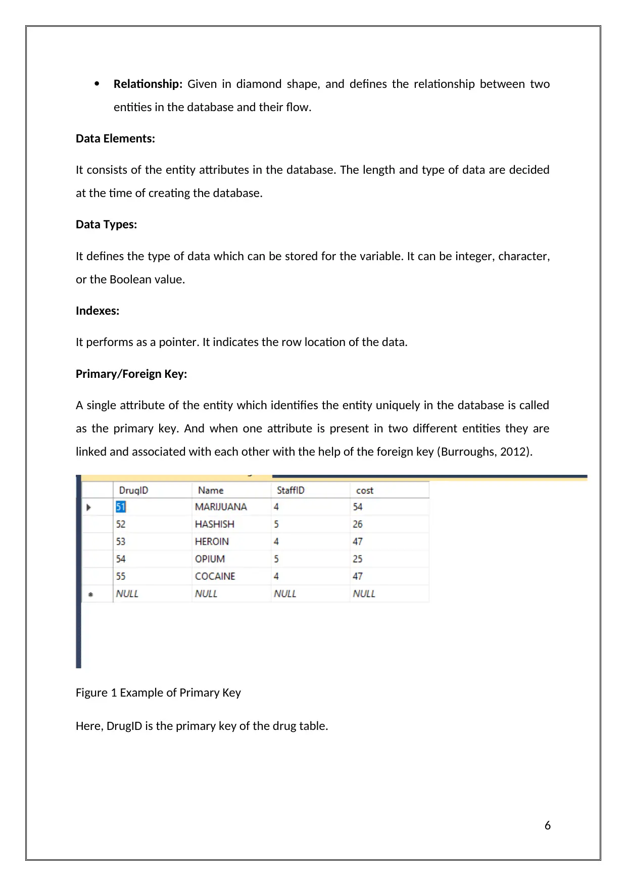
Primary/Foreign Key:
A single attribute of the entity which identifies the entity uniquely in the database is called
as the primary key. And when one attribute is present in two different entities they are
linked and associated with each other with the help of the foreign key (Burroughs, 2012).
Figure 1 Example of Primary Key
Here, DrugID is the primary key of the drug table.
6
entities in the database and their flow.
Data Elements:
It consists of the entity attributes in the database. The length and type of data are decided
at the time of creating the database.
Data Types:
It defines the type of data which can be stored for the variable. It can be integer, character,
or the Boolean value.
Indexes:
It performs as a pointer. It indicates the row location of the data.
Primary/Foreign Key:
A single attribute of the entity which identifies the entity uniquely in the database is called
as the primary key. And when one attribute is present in two different entities they are
linked and associated with each other with the help of the foreign key (Burroughs, 2012).
Figure 1 Example of Primary Key
Here, DrugID is the primary key of the drug table.
6
Paraphrase This Document
Need a fresh take? Get an instant paraphrase of this document with our AI Paraphraser
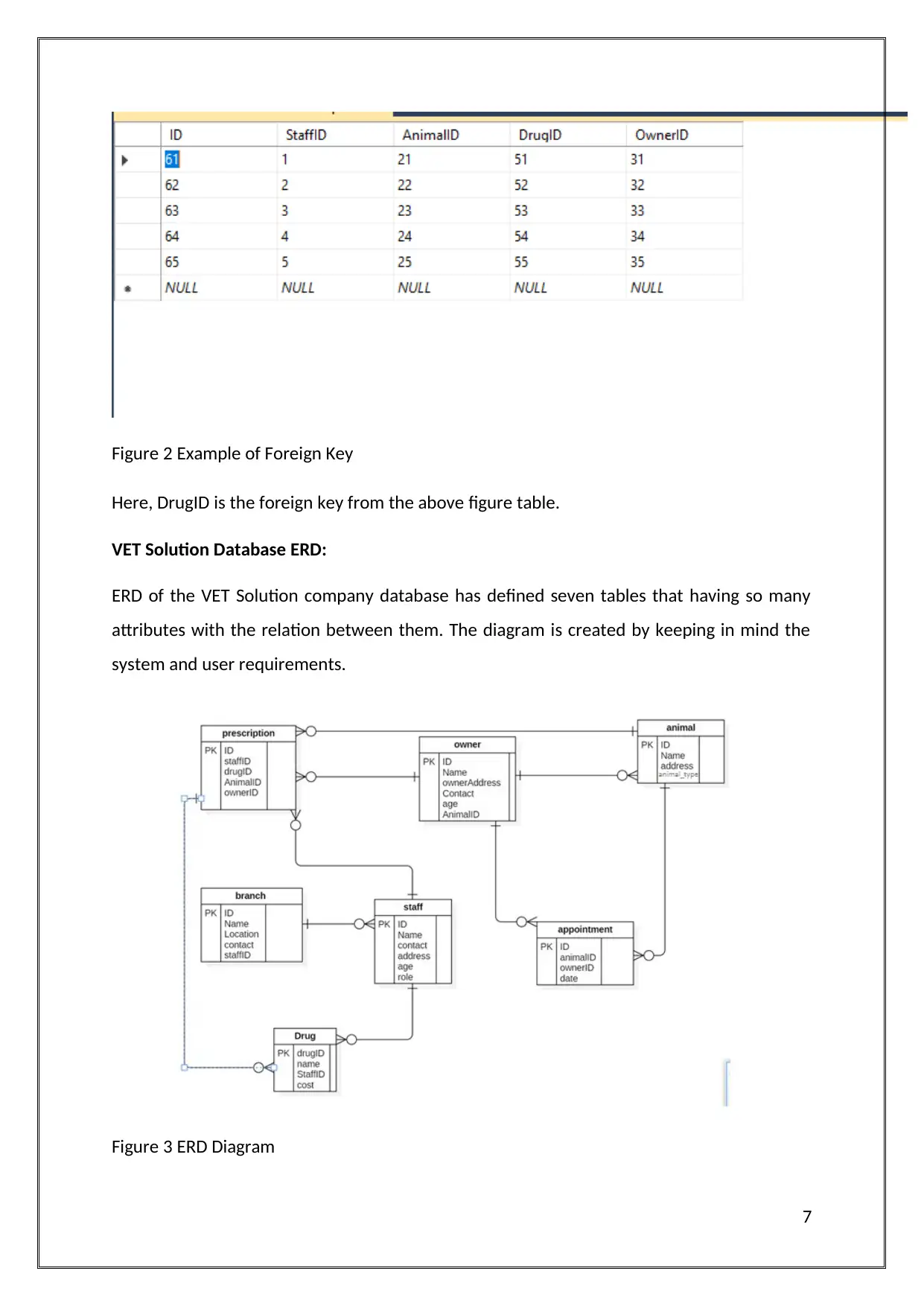
Figure 2 Example of Foreign Key
Here, DrugID is the foreign key from the above figure table.
VET Solution Database ERD:
ERD of the VET Solution company database has defined seven tables that having so many
attributes with the relation between them. The diagram is created by keeping in mind the
system and user requirements.
Figure 3 ERD Diagram
7
Data Integrity:
It is defined as the data accuracy and consistency data in the warehouse. It includes
processing and coding of the data, data validation, and provides assurance of the quality by
testing the data from every point of view.
Data Validation:
By performing some tests, validation of the data can be applied. Also, the index and type of
the data are checked and various conditions are used to check (Xian, 2012).
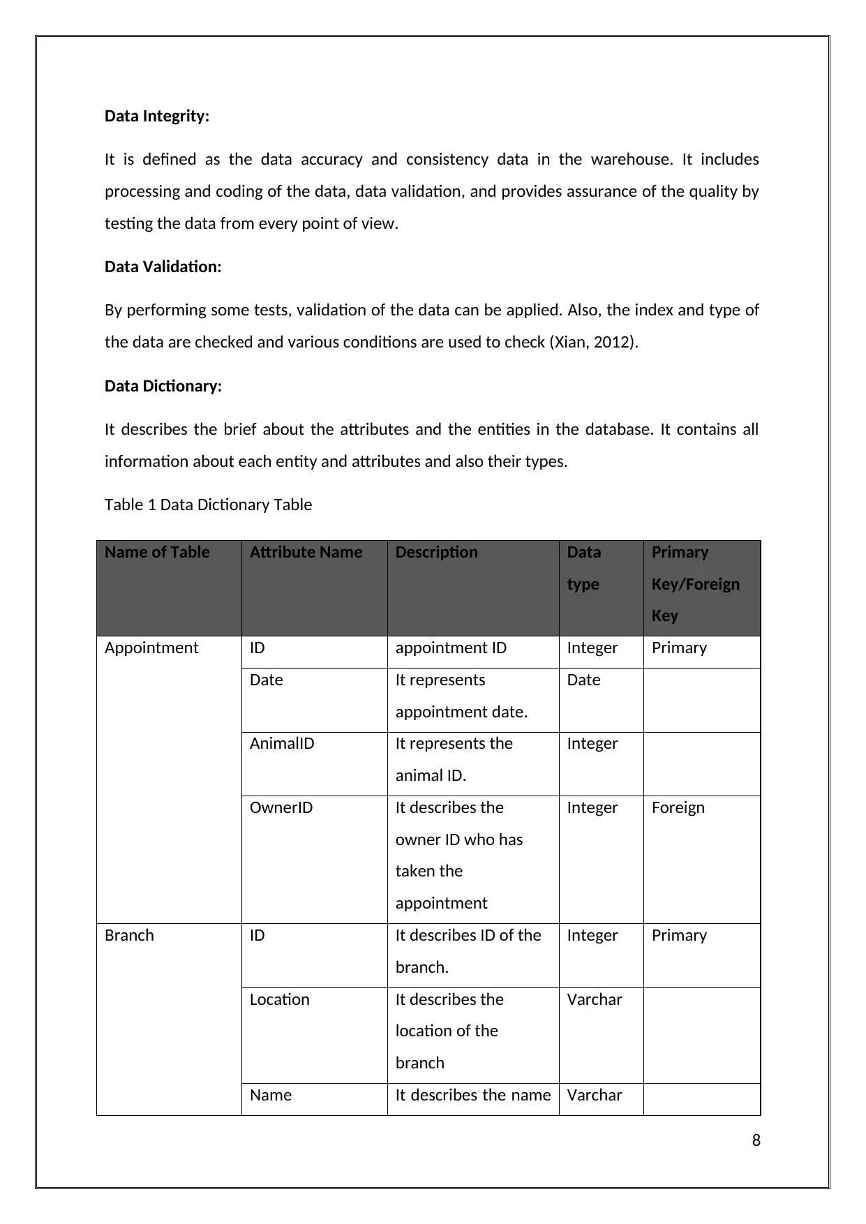
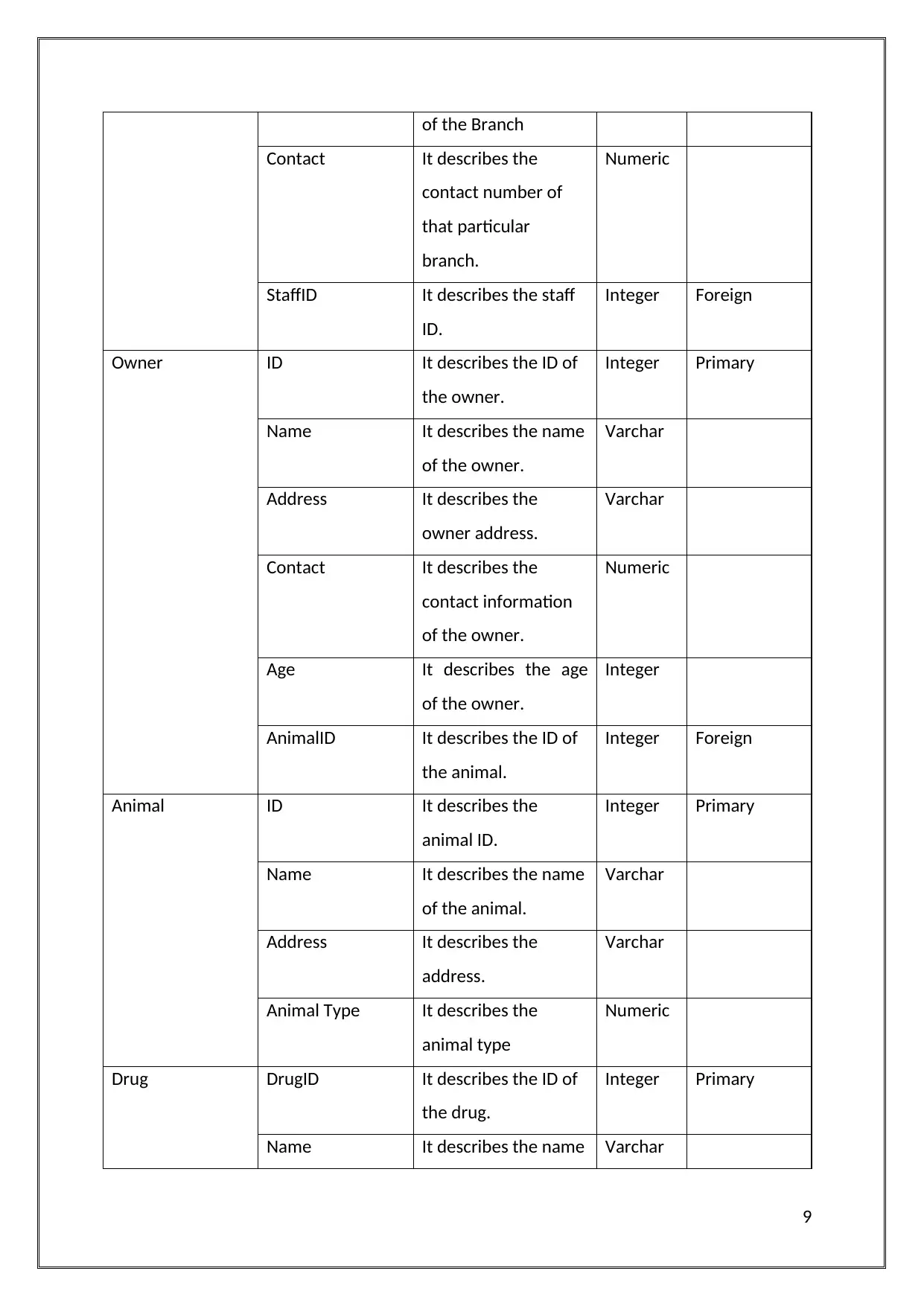
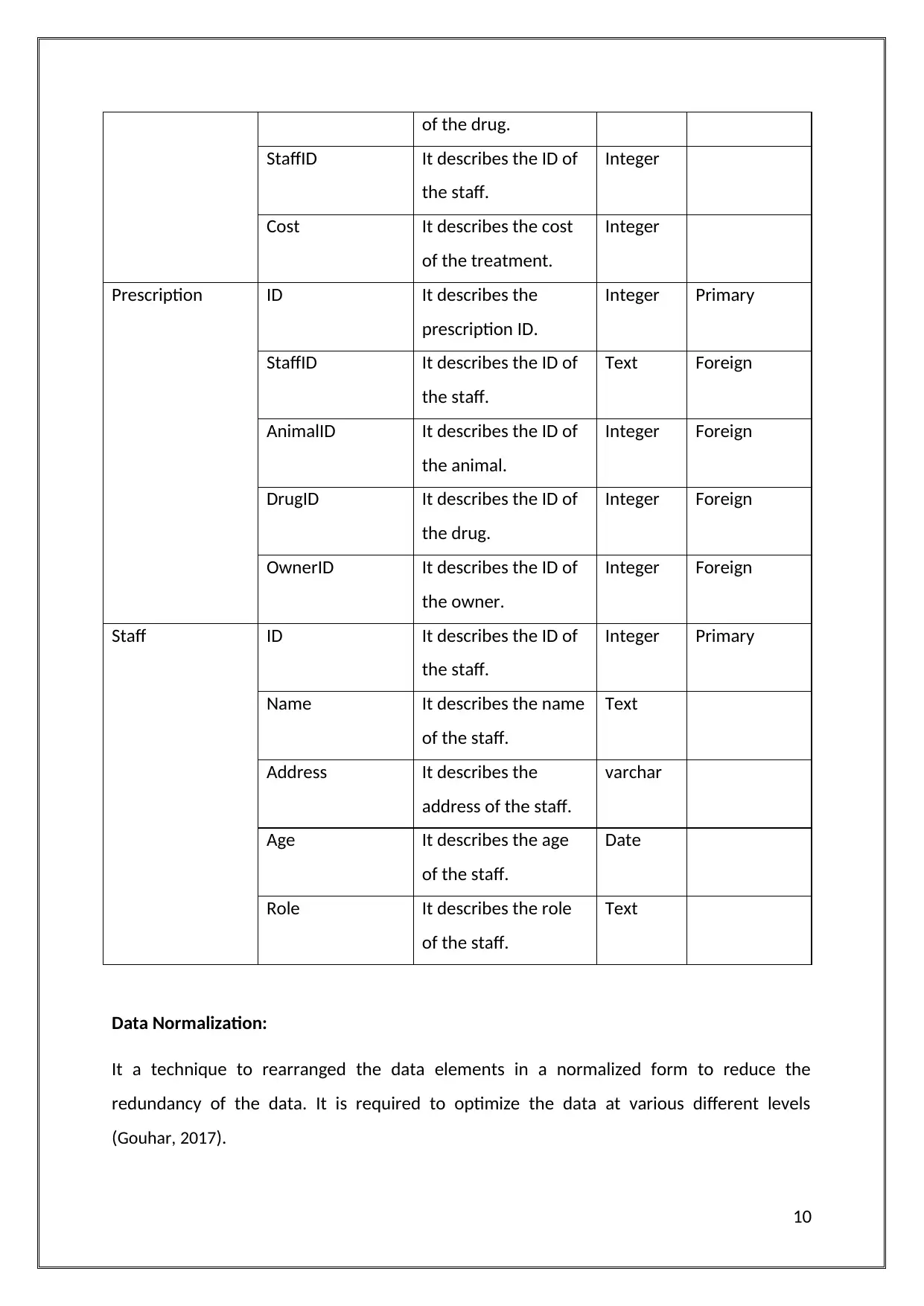
Data Dictionary:
It describes the brief about the attributes and the entities in the database. It contains all
information about each entity and attributes and also their types.
Table 1 Data Dictionary Table
Name of Table Attribute Name Description Data
type
Primary
Key/Foreign
Key
Appointment ID appointment ID Integer Primary
Date It represents
appointment date.
Date
AnimalID It represents the
animal ID.
Integer
OwnerID It describes the
owner ID who has
taken the
appointment
Integer Foreign
Branch ID It describes ID of the
branch.
Integer Primary
Location It describes the
location of the
branch
Varchar
Name It describes the name Varchar
8
It is defined as the data accuracy and consistency data in the warehouse. It includes
processing and coding of the data, data validation, and provides assurance of the quality by
testing the data from every point of view.
Data Validation:
By performing some tests, validation of the data can be applied. Also, the index and type of
the data are checked and various conditions are used to check (Xian, 2012).
Data Dictionary:
It describes the brief about the attributes and the entities in the database. It contains all
information about each entity and attributes and also their types.
Table 1 Data Dictionary Table
Name of Table Attribute Name Description Data
type
Primary
Key/Foreign
Key
Appointment ID appointment ID Integer Primary
Date It represents
appointment date.
Date
AnimalID It represents the
animal ID.
Integer
OwnerID It describes the
owner ID who has
taken the
appointment
Integer Foreign
Branch ID It describes ID of the
branch.
Integer Primary
Location It describes the
location of the
branch
Varchar
Name It describes the name Varchar
8
⊘ This is a preview!⊘
Do you want full access?
Subscribe today to unlock all pages.
Trusted by 1+ million students worldwide
of the Branch
Contact It describes the
contact number of
that particular
branch.
Numeric
StaffID It describes the staff
ID.
Integer Foreign
Owner ID It describes the ID of
the owner.
Integer Primary
Name It describes the name
of the owner.
Varchar
Address It describes the
owner address.
Varchar
Contact It describes the
contact information
of the owner.
Numeric
Age It describes the age
of the owner.
Integer
AnimalID It describes the ID of
the animal.
Integer Foreign
Animal ID It describes the
animal ID.
Integer Primary
Name It describes the name
of the animal.
Varchar
Address It describes the
address.
Varchar
Animal Type It describes the
animal type
Numeric
Drug DrugID It describes the ID of
the drug.
Integer Primary
Name It describes the name Varchar
9
Contact It describes the
contact number of
that particular
branch.
Numeric
StaffID It describes the staff
ID.
Integer Foreign
Owner ID It describes the ID of
the owner.
Integer Primary
Name It describes the name
of the owner.
Varchar
Address It describes the
owner address.
Varchar
Contact It describes the
contact information
of the owner.
Numeric
Age It describes the age
of the owner.
Integer
AnimalID It describes the ID of
the animal.
Integer Foreign
Animal ID It describes the
animal ID.
Integer Primary
Name It describes the name
of the animal.
Varchar
Address It describes the
address.
Varchar
Animal Type It describes the
animal type
Numeric
Drug DrugID It describes the ID of
the drug.
Integer Primary
Name It describes the name Varchar
9
Paraphrase This Document
Need a fresh take? Get an instant paraphrase of this document with our AI Paraphraser
of the drug.
StaffID It describes the ID of
the staff.
Integer
Cost It describes the cost
of the treatment.
Integer
Prescription ID It describes the
prescription ID.
Integer Primary
StaffID It describes the ID of
the staff.
Text Foreign
AnimalID It describes the ID of
the animal.
Integer Foreign
DrugID It describes the ID of
the drug.
Integer Foreign
OwnerID It describes the ID of
the owner.
Integer Foreign
Staff ID It describes the ID of
the staff.
Integer Primary
Name It describes the name
of the staff.
Text
Address It describes the
address of the staff.
varchar
Age It describes the age
of the staff.
Date
Role It describes the role
of the staff.
Text
Data Normalization:
It a technique to rearranged the data elements in a normalized form to reduce the
redundancy of the data. It is required to optimize the data at various different levels
(Gouhar, 2017).
10
StaffID It describes the ID of
the staff.
Integer
Cost It describes the cost
of the treatment.
Integer
Prescription ID It describes the
prescription ID.
Integer Primary
StaffID It describes the ID of
the staff.
Text Foreign
AnimalID It describes the ID of
the animal.
Integer Foreign
DrugID It describes the ID of
the drug.
Integer Foreign
OwnerID It describes the ID of
the owner.
Integer Foreign
Staff ID It describes the ID of
the staff.
Integer Primary
Name It describes the name
of the staff.
Text
Address It describes the
address of the staff.
varchar
Age It describes the age
of the staff.
Date
Role It describes the role
of the staff.
Text
Data Normalization:
It a technique to rearranged the data elements in a normalized form to reduce the
redundancy of the data. It is required to optimize the data at various different levels
(Gouhar, 2017).
10
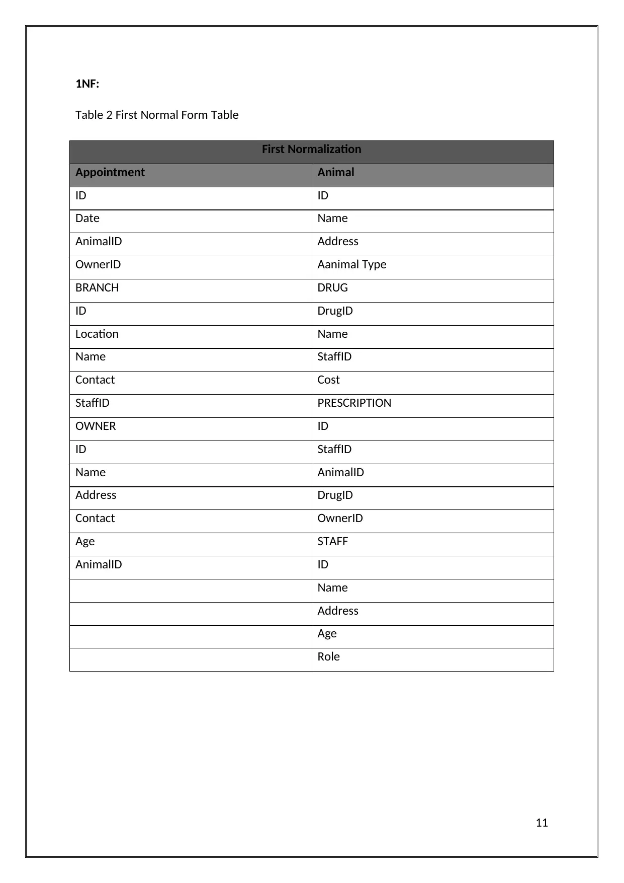
1NF:
Table 2 First Normal Form Table
First Normalization
Appointment Animal
ID ID
Date Name
AnimalID Address
OwnerID Aanimal Type
BRANCH DRUG
ID DrugID
Location Name
Name StaffID
Contact Cost
StaffID PRESCRIPTION
OWNER ID
ID StaffID
Name AnimalID
Address DrugID
Contact OwnerID
Age STAFF
AnimalID ID
Name
Address
Age
Role
11
⊘ This is a preview!⊘
Do you want full access?
Subscribe today to unlock all pages.
Trusted by 1+ million students worldwide
1 out of 39
Related Documents


Your All-in-One AI-Powered Toolkit for Academic Success.
+13062052269
info@desklib.com
Available 24*7 on WhatsApp / Email
![[object Object]](/_next/static/media/star-bottom.7253800d.svg)
Unlock your academic potential
Copyright © 2020–2026 A2Z Services. All Rights Reserved. Developed and managed by ZUCOL.