Detailed Report: TV Remote Control of Electrical Lights & Fans

Verified

Added on  2023/06/10

|10
|1628
|403
Report
AI Summary
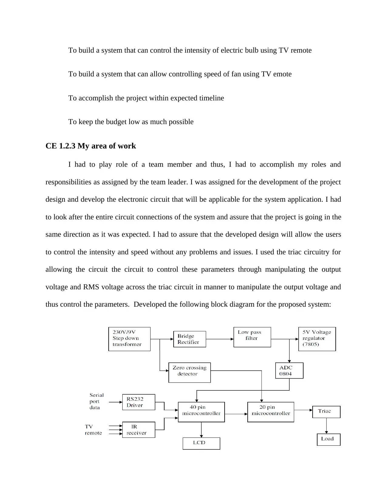
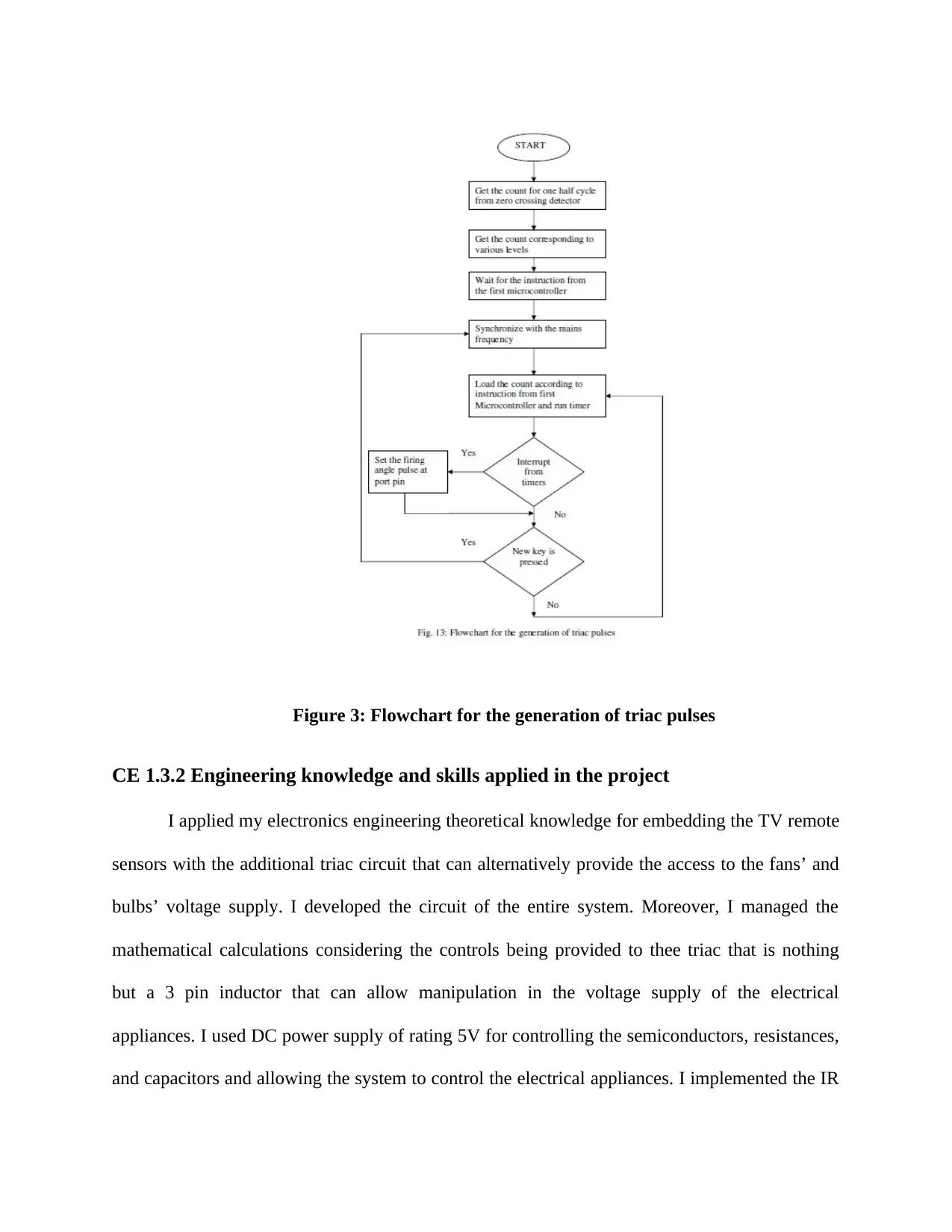
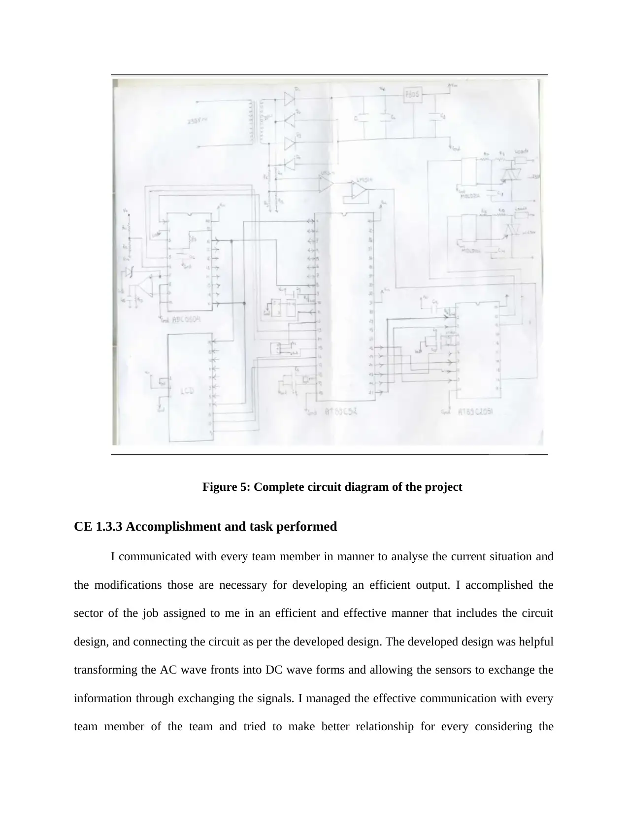
This report details a project focused on developing a system to control electrical lights and fans using a TV remote. The project involved designing and implementing a circuit, primarily utilizing a triac circuit to manipulate the RMS voltage and control the intensity and speed of the connected appliances. The author's role included designing the circuit, ensuring its proper connections, and calculating relevant parameters. The report covers the theoretical background, engineering skills applied, accomplishments, identified issues such as team collaboration and voltage control, and their respective solutions. The project aimed to enhance user convenience by enabling remote control of appliances using readily available TV remotes. The report also provides a detailed overview of the system's design, including block diagrams and circuit diagrams, and highlights the collaborative efforts of the project team.
Document Page
COMPETENCY
DEMONSTRATION REPORT
Career Episode 1
tabler-icon-diamond-filled.svg

Paraphrase This Document

Need a fresh take? Get an instant paraphrase of this document with our AI Paraphraser
Document Page
CE 1.1 Project Information
Name of the project: Using TV Remote to Control Electrical Lights and Fans
Location of the project: [PLEASE FILL]
Project Duration: [PLEASE FILL]
Organization: [PLEASE FILL]
Role and Designation during the time: Team Member
CE 1.2 Project Background
CE 1.2.1 Characteristics of the project
I aimed at developing a product that can enhance the effort of the individuals through
introducing the project that can be utilized for controlling the electrical appliance such as fans
and lights using the TV remote. I proposed the idea of a system that can be helpful in providing
regulation against the input power supply. The speed or intensity of the load can be possibly
controlled through manipulating the RMS voltage across the load through utilizing the triac
circuitry or in other words manipulating the corresponding firing angle at the triac’s gate. The
project was developed for allowing the individuals to operate fans and lights using TV remotes
from anywhere within the short range distance.
CE 1.2.2 Objectives developed for the project
Following objectives were set in manner to allow the team members to concentrate and
move towards the same path and deliver the project successfully:
Document Page
To build a system that can control the intensity of electric bulb using TV remote
To build a system that can allow controlling speed of fan using TV emote
To accomplish the project within expected timeline
To keep the budget low as much possible
CE 1.2.3 My area of work
I had to play role of a team member and thus, I had to accomplish my roles and
responsibilities as assigned by the team leader. I was assigned for the development of the project
design and develop the electronic circuit that will be applicable for the system application. I had
to look after the entire circuit connections of the system and assure that the project is going in the
same direction as it was expected. I had to assure that the developed design will allow the users
to control the intensity and speed without any problems and issues. I used the triac circuitry for
allowing the circuit the circuit to control these parameters through manipulating the output
voltage and RMS voltage across the triac circuit in manner to manipulate the output voltage and
thus control the parameters. Developed the following block diagram for the proposed system:
Document Page
Figure 1: Block diagram of the proposed system
CE 1.2.4 Project Group
CE 1.2.5 My responsibilities throughout the project
I was responsible for designing the circuit and the workflow of the project and make sure
that the proposed circuit is applicable for every users for controlling the intensity and speed of
bulbs and fans without any bugs or glitches. I was responsible for calculating all the parameters
of input and output and incorporating the electronic components those are enough to take the
load and accomplish the activity. I was appointed as a team member and assigned with the
responsibilities other than design and circuit that was to monitor the appliances being utilized is
capable of handling the necessary actions. I purchased the rated electronic components after
calculating the relative values.
tabler-icon-diamond-filled.svg

Paraphrase This Document

Need a fresh take? Get an instant paraphrase of this document with our AI Paraphraser
Document Page
CE 1.3 Distinctive Activity
CE 1.3.1 Comprehending the theory of the project
The triac circuit can be helpful in manipulating the output and input voltage through
controlling the firing angle. I used the property of the triac circuit for controlling the RMS
voltage and thus, control the intensity and speed of the bulb and fan. I used the theory of triac
circuit theory and electrical components for developing the system that will allow the users to
control the electrical appliances using TV remote. I used the IR decoding and triac pulse
generation theory for the development of the system. I implemented or connected the circuits to
accomplish the following listed activities through the electrical components. Following are the
flow chart of the functioning of the proposed system:
Figure 2: Flowchart for IR decoding
Document Page
Figure 3: Flowchart for the generation of triac pulses
CE 1.3.2 Engineering knowledge and skills applied in the project
I applied my electronics engineering theoretical knowledge for embedding the TV remote
sensors with the additional triac circuit that can alternatively provide the access to the fans’ and
bulbs’ voltage supply. I developed the circuit of the entire system. Moreover, I managed the
mathematical calculations considering the controls being provided to thee triac that is nothing
but a 3 pin inductor that can allow manipulation in the voltage supply of the electrical
appliances. I used DC power supply of rating 5V for controlling the semiconductors, resistances,
and capacitors and allowing the system to control the electrical appliances. I implemented the IR
Document Page
sensor, RS232 Driver, IR decoder, zero crossing decoder, voltage regulation of the AC main
power supply, firing pulse generation, and Triac circuit for the development of the entire system.
Triac circuit was the heart of the project whose circuit diagram has been expressed following;
Figure 4: Triac Circuit
I had also embedded the LCD display that was connected to every nodes of the circuit for
displaying the command being executed through the TV remote. I implemented the electrical
components as per the complete circuit diagram developed. I developed the following complete
circuit diagram of the project:
tabler-icon-diamond-filled.svg

Paraphrase This Document

Need a fresh take? Get an instant paraphrase of this document with our AI Paraphraser
Document Page
Figure 5: Complete circuit diagram of the project
CE 1.3.3 Accomplishment and task performed
I communicated with every team member in manner to analyse the current situation and
the modifications those are necessary for developing an efficient output. I accomplished the
sector of the job assigned to me in an efficient and effective manner that includes the circuit
design, and connecting the circuit as per the developed design. The developed design was helpful
transforming the AC wave fronts into DC wave forms and allowing the sensors to exchange the
information through exchanging the signals. I managed the effective communication with every
team member of the team and tried to make better relationship for every considering the
Document Page
development and execution of the project objectives. The sensors and the semiconductors used
were effective and efficient in exchanging the information and allowing the users to accomplish
the necessary outcome through TV remotes.
CE 1.3.4 Identified issues and their solutions
1.3.4.1 Issues
The first issue that was becoming an obstacle in the successful delivery of the project was
the collaboration between the team members due to the lack of communication between the team
members. I identified that in manner to control the intensity and speed of the electrical
appliances, it was the crucial factor to manage and control the output voltage remotely in manner
to manage and control the output voltage remotely.
1.3.4.2 Solutions
I managed to make better relationship with every team member and established an
effective and efficient communication strategy that alternatively helped in understanding their
perspectives and delivering the necessary output. I used three terminals triac semiconductor
who’s functioning was that “If a turn on pulse is applied, the triac goes from a high-impedance
state to a conductive state, and it starts conducting current through the load. So the position at
which this turn on pulse is fired (firing angle) directly control the percentage power of that half-
cycle transmitted to the load.”
CE 1.3.5 Plan to produce creative and innovative work
I gathered lots of research papers and books in addition to the course books to identify the
characteristics of the stereotype remotes and how it can be used to control the intensity and speed
of the bulbs and fans. Proposing the system will be helpful in enhancing the comfort zone of the
Document Page
common people. I also researched many papers proposed with similar type of projects for the
consideration of the ideas those could be enhanced and implemented in different ways within the
project. I used the TV remote in the place of the separate remote in manner to assure that there is
always availability of the source for the accomplishment of the activities.
CE 1.3.6 Collaborative work
The project was consist of five members including the Assistant professor, team leader
and three team members. I was playing the role of the team member and I managed to
accomplish all the commands and orders provided by the team leader. At some of the instances, I
had to take the initiative in manner to assure that the project being delivered is of high standard. I
established a communicative environment in which every team member was supposed to
communicate with each other related to the issues, progress, and necessary activities those were
still left.
CE 1.4 Project Review
CE .4.1 Project Overview
The developed project will allow the users to control the intensity and speed of the bulb
and fan at eight different levels and make sure that the system functions in an efficient and
effective manner. I developed the design of the project that was one of the important section of
the project including design, development and testing. I contributed in the development of the
design, circuit connections, and mathematical calculations those could be utilized for the
development of the system that will be long lasting. I contributed in the team contributions
considering the operational activities, management of the team and as a quality investigator.
chevron_up_icon
1 out of 10
circle_padding
hide_on_mobile
zoom_out_icon
[object Object]