Network Design Report: Configuration, Implementation, and Testing

Verified

Added on  2019/11/14

|24
|1753
|200
Report
AI Summary
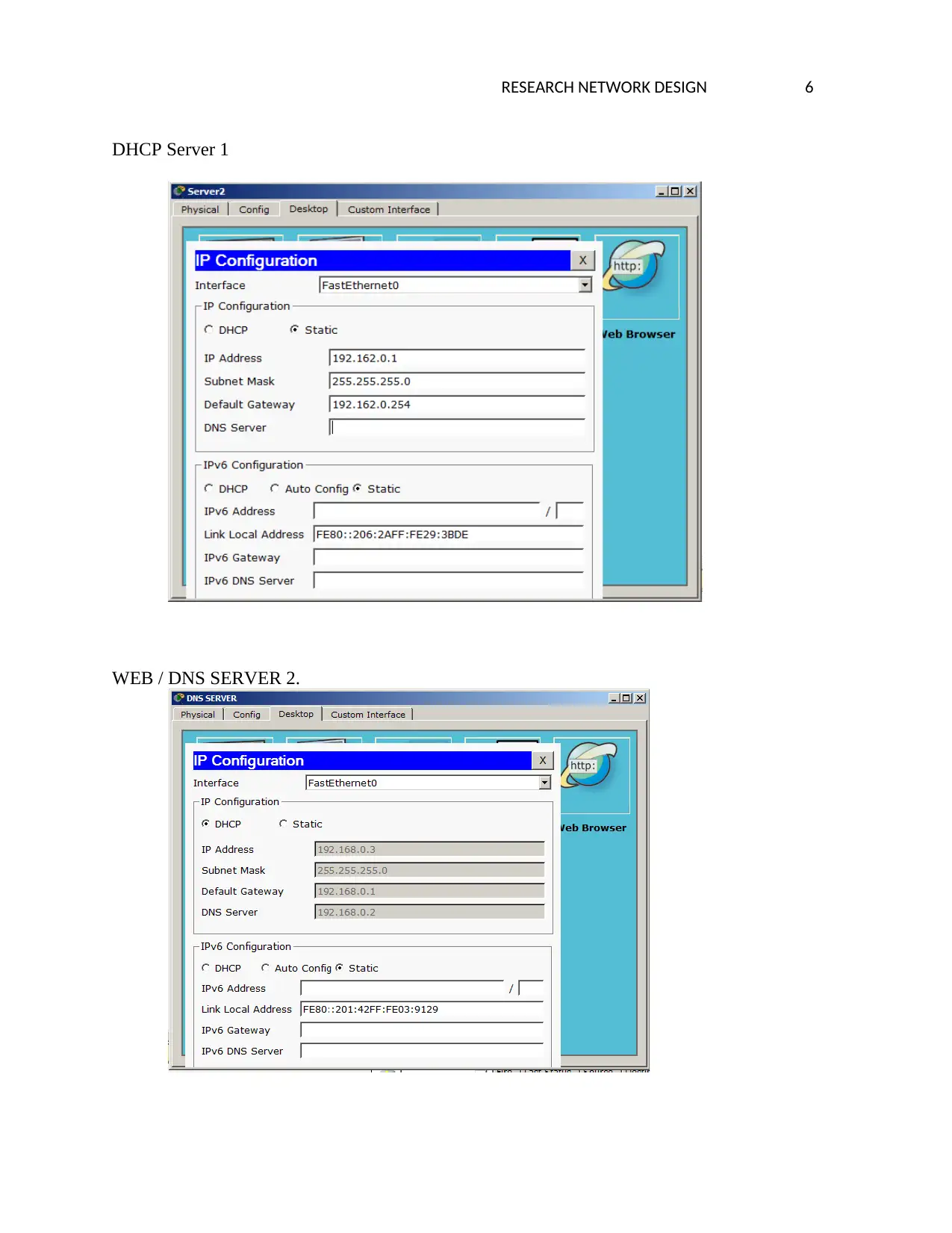
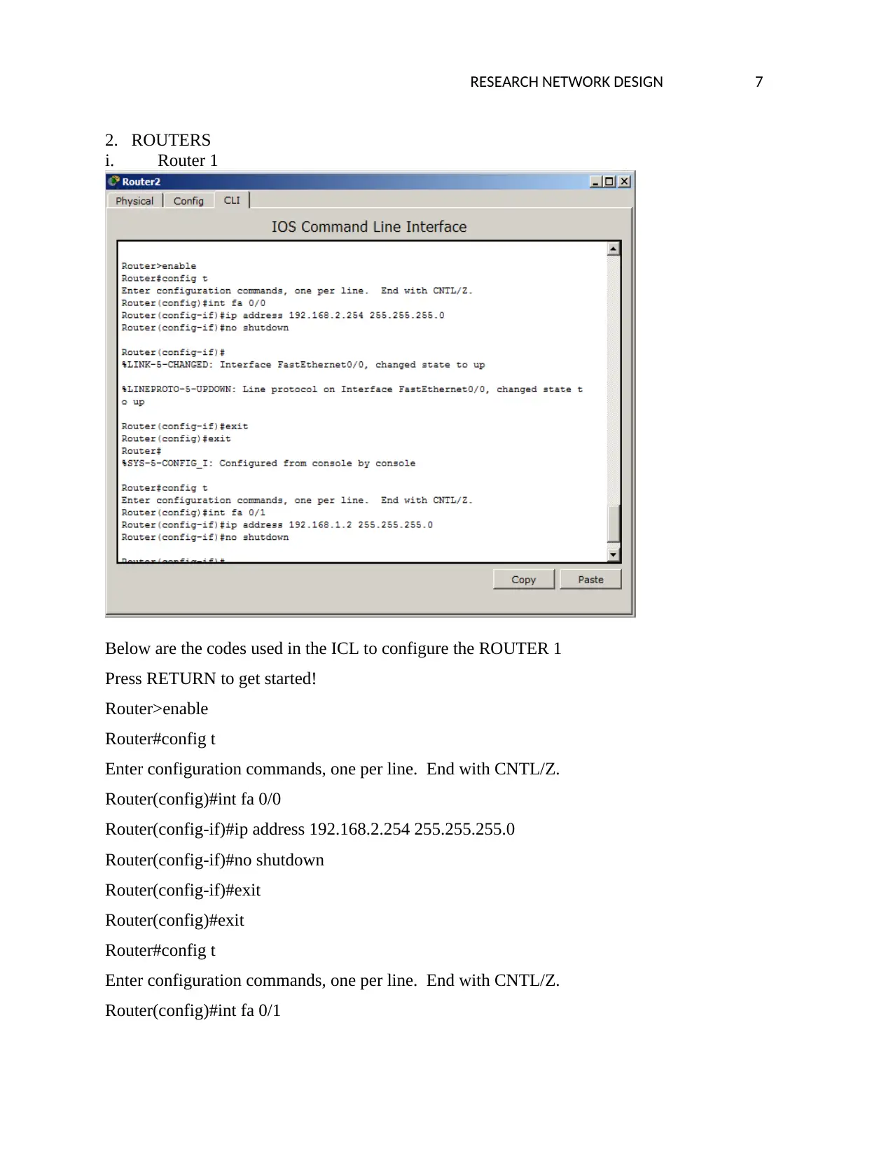
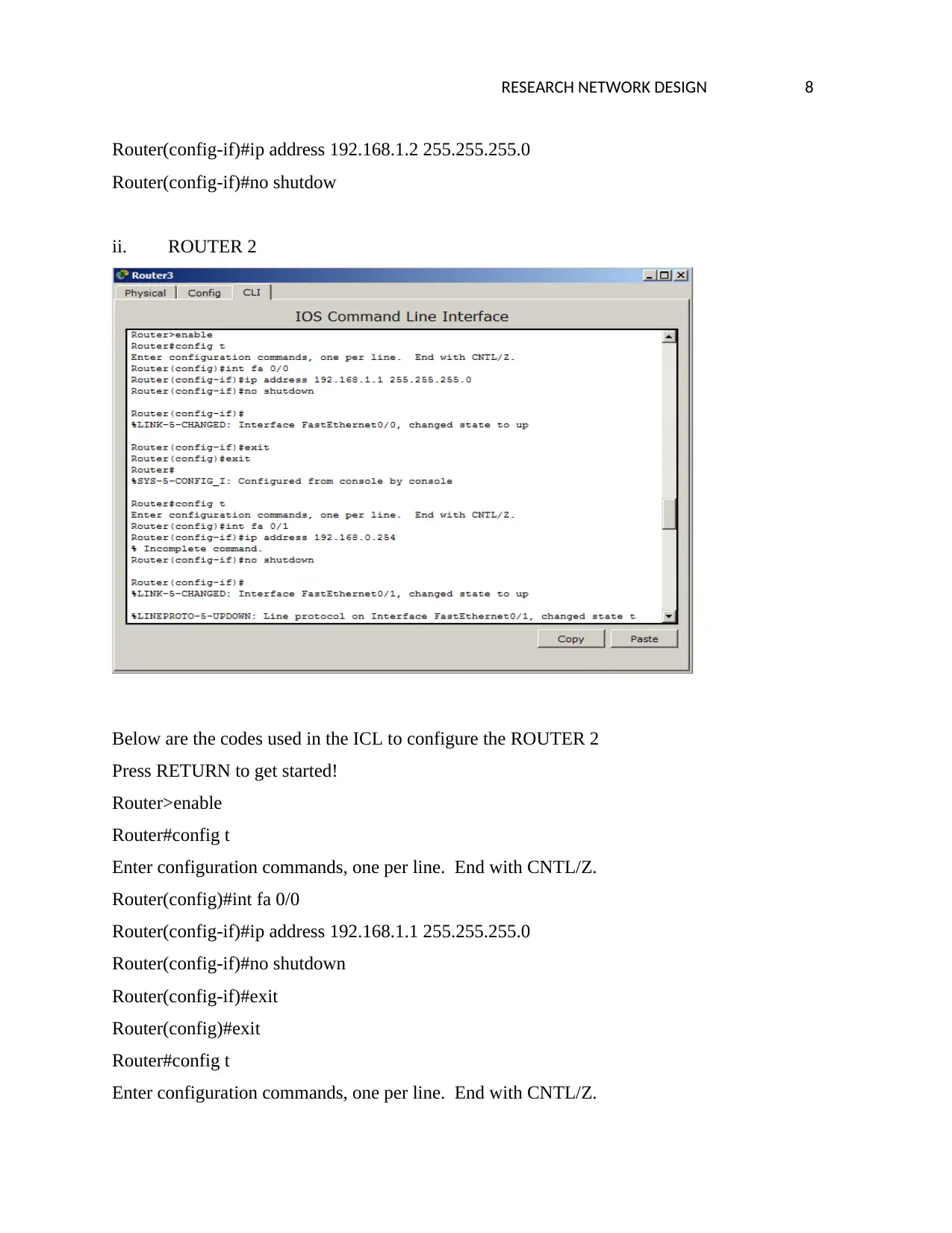
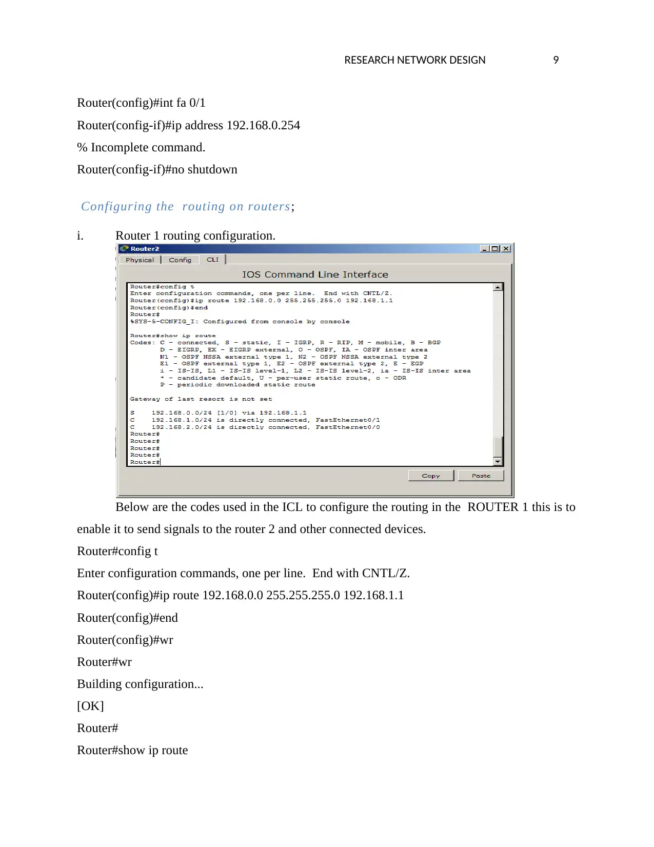
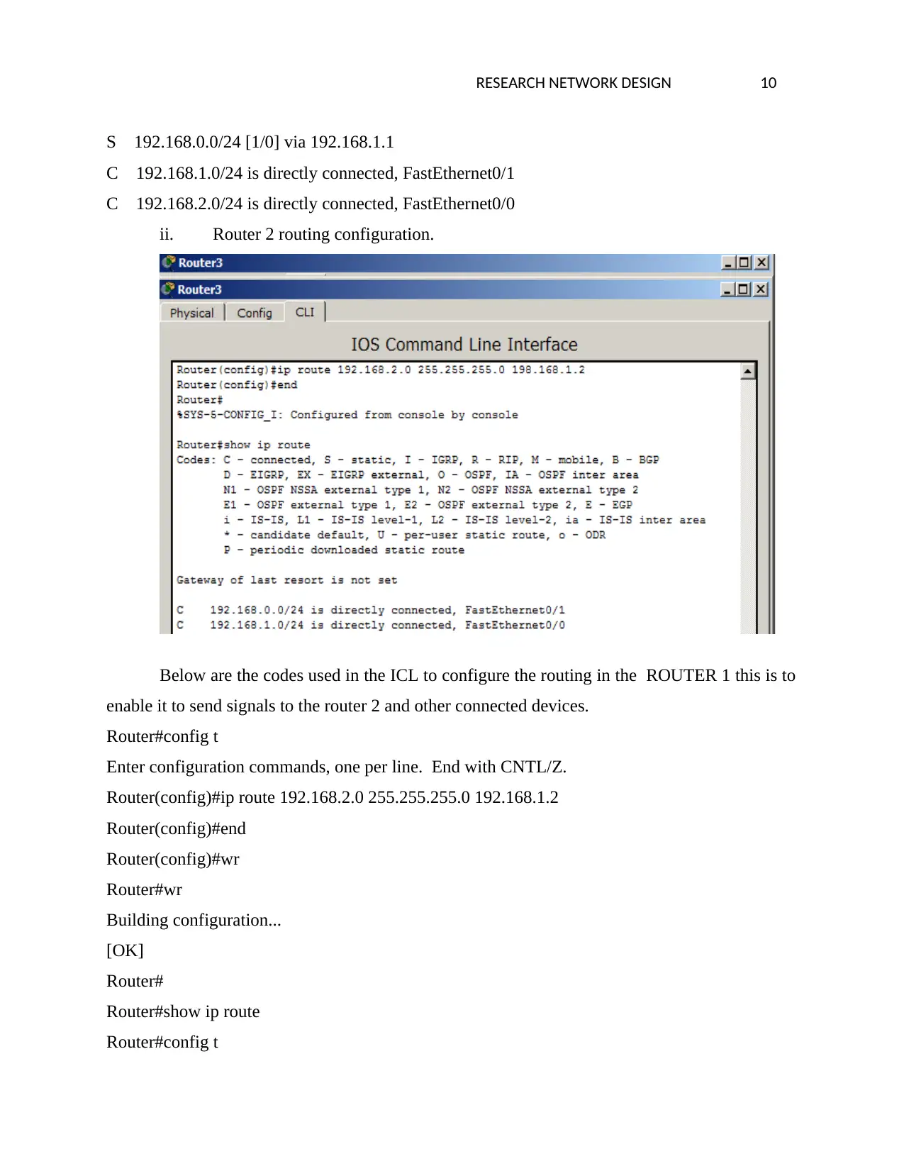
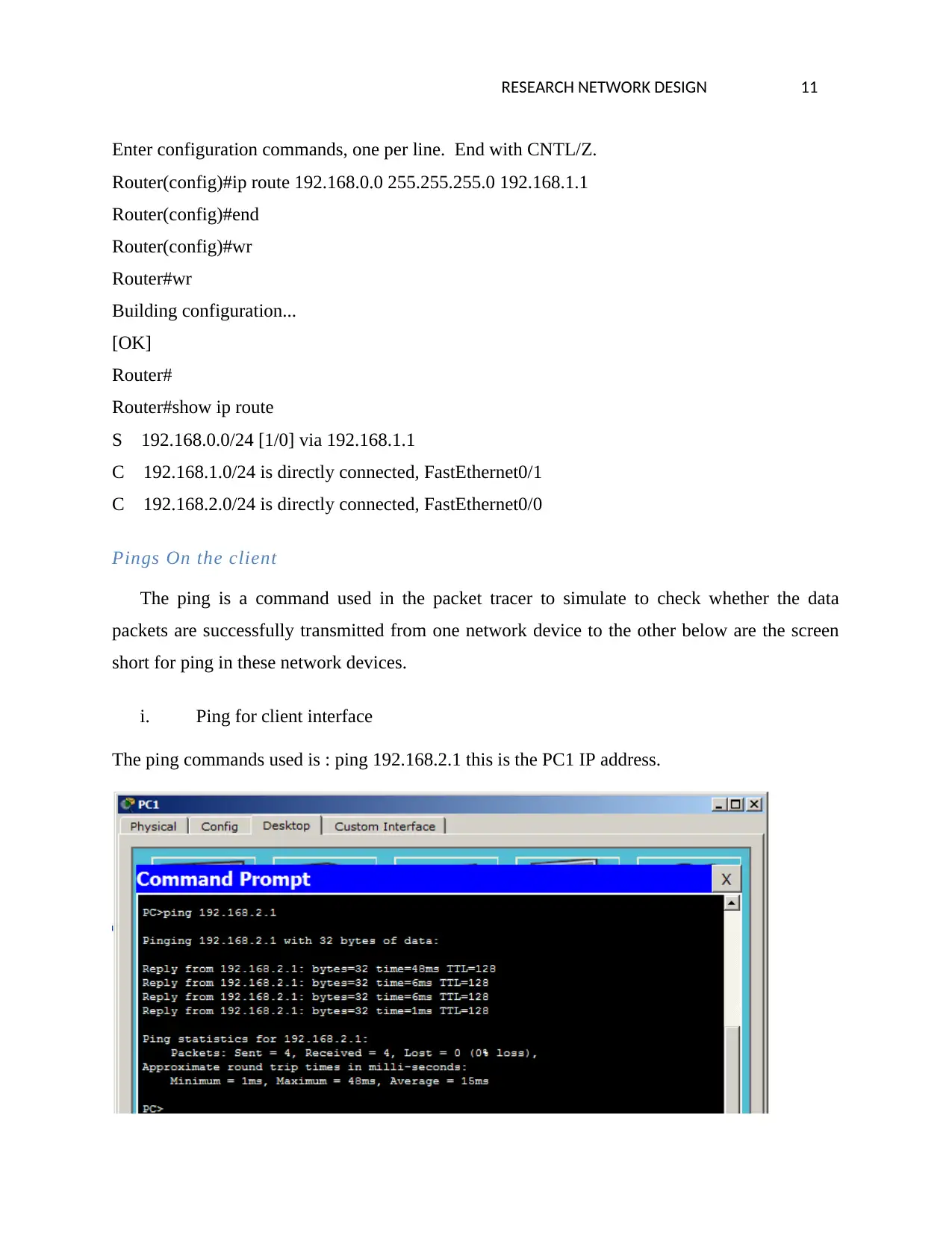
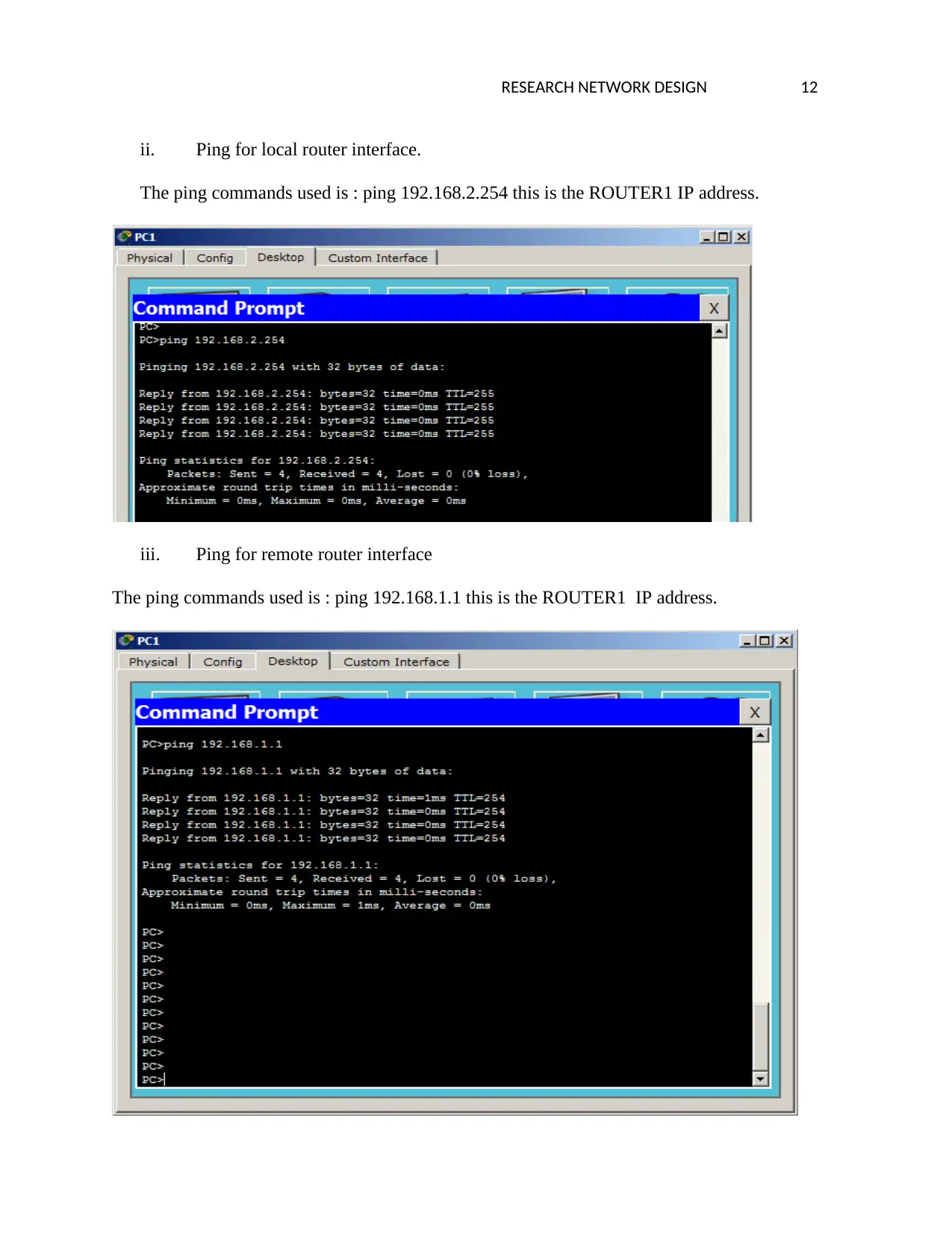
This report details the design and implementation of a network, encompassing the configuration of network devices, including routers, computers, and servers. It begins with an executive summary outlining the report's scope, which involves designing an IP address scheme, configuring routers to connect two local area networks, and setting up servers for DHCP, web services, and DNS. The report then presents the network setup, detailing device configurations with IP addresses, subnet masks, and default gateways. It includes screenshots of the configured devices and the ICL codes used for router configurations, specifically focusing on interface setup, IP addressing, and routing protocols. Task 1 covers the configuration of PCs, servers, and routers, including screenshots of the configuration process. Task 2 focuses on configuring network services, including DHCP server setup, web server configuration, DNS server configuration, and firewall implementation to block TCP traffic. The report includes ping and traceroute tests to verify network functionality and concludes with a list of references to support the information presented.
Document Page
Running Head: RESEARCH NETWORK DESIGN 1
Research Network Design
[Assessment No]
[Student Names]
[Student ID]
[Student Email]
[Institution Name]
tabler-icon-diamond-filled.svg

Paraphrase This Document

Need a fresh take? Get an instant paraphrase of this document with our AI Paraphraser
Document Page
RESEARCH NETWORK DESIGN 2
Executive summary
This is a report which entails the various network configurations; however it involves the
designing of the network address scheme where the various network devices are assigned some
specific web addresses.
However the report covers the configuration of the network devices where there are two
routers that links two local area networks and the servers, all these are configured and the ip
addresses are assigned.
Each network router is also configured to enable the communication between all the
network devices where the functionality is tested by ping command which is done using one
computer to the routers and the connected servers.
The network also is linked with servers which are configured as DHCP servers ,web
servers, and DNS servers respectively this is to improve the services offered in the network. The
network also is configured by setting up the firewall to ensure the signals cannot be transmitted
in unintended locations.
Document Page
RESEARCH NETWORK DESIGN 3
TASK 1
Setting up a Network
Below is the set network that is having two subnetworks with two routers which links
them ,however there are three computers and two servers as shown below.
Configuration of the PC, Server and Router
The below is the illustration of the configured Pcs, server and the routers this
is implemented using the following table indicating the addressing scheme used.
This network address was class c network and the network gateway used is
255.255.255.0 below is the summary of the respectively.
Device name Ip address Subnet mask Default Gateway
Pc1 192.168.2.2 255.255.255.0 192.168.2.254
Pc1 192.168.2.1 255.255.255.0 192.168.2.254
Document Page
RESEARCH NETWORK DESIGN 4
Pc2 192.168.0.2 255.255.255.0 192.168.0.254
Server 1 192.168.0.1 255.255.255.0 192.168.0.254
Server 2 192.168.0.3 255.255.255.0 192.168.0.254
Router1 192.168.2.254
192.168.1.2
255.255.255.0
255.255.255.0
192.168.2.254
192.168.2.254
Router 2 192.168.0.254
192.168.1.1
255.255.255.0
255.255.255.0
192.168.2.254
192.168.2.254
Below is the screenshots for the configured devices.
1. COMPUTERS
Computer 1 –PC0
tabler-icon-diamond-filled.svg

Paraphrase This Document

Need a fresh take? Get an instant paraphrase of this document with our AI Paraphraser
Document Page
RESEARCH NETWORK DESIGN 5
Computer 2-pc1
Computer 3 –PC2
Document Page
RESEARCH NETWORK DESIGN 6
DHCP Server 1
WEB / DNS SERVER 2.
Document Page
RESEARCH NETWORK DESIGN 7
2. ROUTERS
i. Router 1
Below are the codes used in the ICL to configure the ROUTER 1
Press RETURN to get started!
Router>enable
Router#config t
Enter configuration commands, one per line. End with CNTL/Z.
Router(config)#int fa 0/0
Router(config-if)#ip address 192.168.2.254 255.255.255.0
Router(config-if)#no shutdown
Router(config-if)#exit
Router(config)#exit
Router#config t
Enter configuration commands, one per line. End with CNTL/Z.
Router(config)#int fa 0/1
tabler-icon-diamond-filled.svg

Paraphrase This Document

Need a fresh take? Get an instant paraphrase of this document with our AI Paraphraser
Document Page
RESEARCH NETWORK DESIGN 8
Router(config-if)#ip address 192.168.1.2 255.255.255.0
Router(config-if)#no shutdow
ii. ROUTER 2
Below are the codes used in the ICL to configure the ROUTER 2
Press RETURN to get started!
Router>enable
Router#config t
Enter configuration commands, one per line. End with CNTL/Z.
Router(config)#int fa 0/0
Router(config-if)#ip address 192.168.1.1 255.255.255.0
Router(config-if)#no shutdown
Router(config-if)#exit
Router(config)#exit
Router#config t
Enter configuration commands, one per line. End with CNTL/Z.
Document Page
RESEARCH NETWORK DESIGN 9
Router(config)#int fa 0/1
Router(config-if)#ip address 192.168.0.254
% Incomplete command.
Router(config-if)#no shutdown
Configuring the routing on routers;
i. Router 1 routing configuration.
Below are the codes used in the ICL to configure the routing in the ROUTER 1 this is to
enable it to send signals to the router 2 and other connected devices.
Router#config t
Enter configuration commands, one per line. End with CNTL/Z.
Router(config)#ip route 192.168.0.0 255.255.255.0 192.168.1.1
Router(config)#end
Router(config)#wr
Router#wr
Building configuration...
[OK]
Router#
Router#show ip route
Document Page
RESEARCH NETWORK DESIGN 10
S 192.168.0.0/24 [1/0] via 192.168.1.1
C 192.168.1.0/24 is directly connected, FastEthernet0/1
C 192.168.2.0/24 is directly connected, FastEthernet0/0
ii. Router 2 routing configuration.
Below are the codes used in the ICL to configure the routing in the ROUTER 1 this is to
enable it to send signals to the router 2 and other connected devices.
Router#config t
Enter configuration commands, one per line. End with CNTL/Z.
Router(config)#ip route 192.168.2.0 255.255.255.0 192.168.1.2
Router(config)#end
Router(config)#wr
Router#wr
Building configuration...
[OK]
Router#
Router#show ip route
Router#config t
tabler-icon-diamond-filled.svg

Paraphrase This Document

Need a fresh take? Get an instant paraphrase of this document with our AI Paraphraser
Document Page
RESEARCH NETWORK DESIGN 11
Enter configuration commands, one per line. End with CNTL/Z.
Router(config)#ip route 192.168.0.0 255.255.255.0 192.168.1.1
Router(config)#end
Router(config)#wr
Router#wr
Building configuration...
[OK]
Router#
Router#show ip route
S 192.168.0.0/24 [1/0] via 192.168.1.1
C 192.168.1.0/24 is directly connected, FastEthernet0/1
C 192.168.2.0/24 is directly connected, FastEthernet0/0
Pings On the client
The ping is a command used in the packet tracer to simulate to check whether the data
packets are successfully transmitted from one network device to the other below are the screen
short for ping in these network devices.
i. Ping for client interface
The ping commands used is : ping 192.168.2.1 this is the PC1 IP address.
Document Page
RESEARCH NETWORK DESIGN 12
ii. Ping for local router interface.
The ping commands used is : ping 192.168.2.254 this is the ROUTER1 IP address.
iii. Ping for remote router interface
The ping commands used is : ping 192.168.1.1 this is the ROUTER1 IP address.
chevron_up_icon
1 out of 24
circle_padding
hide_on_mobile
zoom_out_icon
[object Object]