AS1684.4 Timber-Framed Construction: Code Compliance and Analysis
VerifiedAdded on 2023/06/16
|12
|2705
|385
Homework Assignment
AI Summary
This document presents a student's solution to an assessment focused on AS1684.4, addressing various aspects of residential timber-framed construction. The assessment covers topics such as floor framing, including compliance with wind classification, plan considerations, number of stories, width, wall height, rafter overhang, and roof types. It also examines the applicability of AS1684 for floor design, concrete slab edge beam depth, drainage requirements, the role of fill, controlled and rolled fill, bearing pressure, external wall details, damp-proof courses, flashing, and the appropriate fixation of nails for hardwoods and softwoods. Furthermore, it delves into specific fixing requirements based on rafter span and wind classification, common stud specifications, and bracing requirements according to wind direction, offering a comprehensive overview of key considerations in timber-framed residential building design and construction, as well as the importance of consulting Desklib for additional resources.
ASSESSMENT 7
Student’s Name:
Institutional Affiliation:
Student’s Name:
Institutional Affiliation:
Paraphrase This Document
Need a fresh take? Get an instant paraphrase of this document with our AI Paraphraser
Floor framing
Question 1(Using AS1684)
i) According to the architectural plans, the maximum width of the building is 8.150
meters. The width falls within the maximum allowable width designated for N2 areas
by clause 1.4.5 which is 12m.The recommendation is outlined in clause 1.4.2 which
deals with cyclonic and non-cyclonic areas.
ii) According to the plans, the building can be designed in the area. Clause 1.4.3 states
that the building should be of either rectangular, square or L-shapes, or a combination
of rectangular elements. From the plan, the building is a combination of 3 rectangular
shapes and therefore no restriction.
iii) Clause 1.4.4 limits the number of storeys to 2 and as such, the building is in a safe
position with 0 storeys.So yes, the building can be designed
iv) The maximum width of the building is 8.150 meters. Therefore, the building falls
within the maximum allowable width of 12.0 meters, as stipulated by clause1.4.5.
v) The section A-A indicates that the height of the wall can be obtained from 12.450 –
9.750 which equals 2700mm, the maximum height as stipulated by clause 1.4.6.
vi) Clause 1.4.7 recommends that the maximum rafter overhang should be 750
mm.Acccording to the drawing plans and approximations, the overhang can be
estimated by adding 380+250=630.The approximation falls within the required
maximum.
vii) The roof types recommended by clause 1.4.10 are: hip, gable.skillion.cathedral,
trussed, pitched or any suitable combination. According to the plans of the building,
the most suitable combination, according to the varying ridges and valleys, would be

that of a gable, hip and pitched roofs. The cathedral roofing system is suitable for the
patio.
Question 2
According to AS1684, clause 4.1.2, the standards stipulates that the material to be used for
the flooring system should be timber regardless of the species. Furthermore, the AS1684
outlines the practice design for timber floors but does not consider concrete anywhere. In line
with designing the building, it is not possible to use this standard because the building has a
concrete floor.
Question 3
A class S site refers to a place where the clay is slightly reactive and the ground movements
are minimal. As per BCA volume 2-2010 figure 5.2.3(a) and the table, the depth of a site S
edge beam for masonry veneer as well as articulated masonry veneer is 300mm.
Question 4
There are three specifications when it comes to the drainage specifications. BCA 2010
volume 2 clause 3.1.2.3 outlines the height of the slab above the finished ground level in:
areas of low intensity rainfall, impermeable surfaces and any other cases. In this scenario, the
most appropriate height is 150mm
Question 5
Fill may have been a necessity during the earth works and this is indicated by sharp
gradients as described by the contours. According to BCA volume 2 clause 3.1.1.4, filling
may be necessary where: fill is deeper than the existing soil level and for protection of the
⊘ This is a preview!⊘
Do you want full access?
Subscribe today to unlock all pages.
Trusted by 1+ million students worldwide
footing system.Furthermore,fill is necessary for drainage of the area and as such, it cannot be
simply overlooked in this case.
Question 6
Controlled fill refers to material that has been placed and compacted in layers using
compaction equipment within a defined moisture range to a defined density while rolled fill
refers to material that has been placed in layers and compacted by continuous rolling by an
excavator.
kPa is a measurement unit that defines the ability of a material to withstand a force over a
specified area. It is used to define bearing pressure which is the strength of the soil and its
ability to withstand loads applied through the foundation.
The bearing pressure on which the slab edge beam is to be connected should not be less than
50kPa in natural soils. This is in accordance to clause 3.2.2.3 BCA volume 2
Question 7
The figure 3.2.5.3 of BCA volume 2-2010 resembles the external detail of the external wall
because of the construction methodology employed.Accordinmg to the figures, the
foundations is made up of internal and edge beams which are to ensure that the loads from
the load bearing walls are distributed appropriately into the ground
Question 8
A DPC is a membrane that prevents the penetration of water and moisture into a building.
The membrane forms a continuous barrier around the building, walls and piers below
Paraphrase This Document
Need a fresh take? Get an instant paraphrase of this document with our AI Paraphraser
suspended walls, therefore preventing the ground water from penetrating into the
aforementioned elements.
Question 9
According to BCA volume 2,flashing refers to a strip or sleeve of impervious material
dressed, fitted or built-in to provide a barrier to moisture movement, or to divert the
travel of moisture, or to cover a joint where water would otherwise penetrate to the
interior of a building.
Question 10
There are a number of instances that may require installation of flashing. Some of the places
where flashing is observed include: chimney, roof butting a wall, sill and head flashing, the
base of cavity walls
Question 11
AS1684 table
used
Timber
stress grade
Span
mm
Spacing
mm
Single or
continuous
span used for
sizing?
Size
(mm x mm)
Post (note:
footing
type 2)
3.2
F11 xxxx 1800 xxxx 100 100
Bearers A7 Unseasoned
F11 1800 1500 Continuous 125 75
Joist A8 Unseasoned
F11 3600 450 continuous 175 38
Decking Outdoor
structures
Australia
Australian
Spotted gum 1800 20 xxxx 65 19
Question 12
There are four types of walls that use brickwork. Brick veneer, reverse brick veneer, double
brick and the solid. The first case involves covering the external wall surface with a bricks
while the reverse case involves covering the internal surfaces with bricks. Basically, these are
insulation measures and provide the wall surface with an exquisite finish. In Australia, brick
veneer has been the widely adopted system for brick walling but the cavity sizes as well as
the sizes of openings have been greatly studied and revised in most standards. It has been
stated that the walls with the appropriate cavities are very effective in ventilation and drying.
As a matter of fact, walls with cavities have the ability to dry three times faster than those
without cavities. It is this factor that makes them effective water barriers.
AS 3700:2001 requires that the openings should be about 76mm by breadth with the centers
at a maximum of 1200mm.Therefore, the system equates to 633m2 opening area for every
meter of brick wall. These standards may also be found in the BCA.
Question 13
AS1684 provides a platform for the designer to ensure that there is appropriate fixation of
nails to both the hardwoods and softwoods. Clause 9.5 details the nominal fixings. In this, the
clause tries to indicate the diameters of the nails to be used for the framing of both softwoods
and hardwoods. As the clause indicates, there is a minimum requirement for the diameter for
the nailing that are machine driven. The diameter for hardwood is 3.05mm while that for
softwood is 3.33mm.The difference in diameter arises from the ease as well as the difficulty
of penetration. Furthermore, the clause indicates the types as well as the length of nails that
will be used in each scenario. However, the designer has to consider the wind classification
system into which the building falls. Some nominal fixing of the buildings as per the design
are indicated below.
⊘ This is a preview!⊘
Do you want full access?
Subscribe today to unlock all pages.
Trusted by 1+ million students worldwide
A) The nominal fixing requirements from the bottom plate to the slab. The requirements are
indicated in table 9.3 and in this, the table indicates that the nails needed have to be
75mm and of the masonry type (hand driven at the edge of the slab).Furthermore, the
maximum spacing of screwing and bolting from center to center is 1200mm.
B) .C). The nominal fixing requirement from the studs to the bottom plate are specified in
table 9.3.however, AS1684.4-2006 does not consider the difference in direction. The
standards does not separate the fixing requirements of the studs to the bottom plate and
the studs to the top plate. As a general rule, the table indicates the fixing requirements of
the plates to the studs. There are two types of plates that are defined by table 9.3:plates up
to 38mm thick and plates whose thickness is between 38mm and 50mm.The former
plates require 2/75 3.05mm nails through the plate while the latter require 2/90 3.05mm
nails through the plate. Furthermore, 2/75 3.05mm nails may be skewed through the stud and
into the plate.
Question 14
The specific fixing requirements of a building are outlined by AS1638 clause 9.6.1 and
detailed in table 9.4.The specific fixing requirements are an addition to the nominal fixing
requirements and determined by the roofing system as well as the wind classification.
A) To begin with, we need to determine the specific fixing requirements from the bottom
plate to the slab. The only requirement is the rafter or truss spanning. In this case, the
details given are that the truss span is 7830mm and the fixing are 600mm center to center.
Therefore, because there are only four spans offered in table 9.6 (3000, 6000, 9000 and
12000), the span to be employed in the design is that of 9000mm.The fixing requirements
are as follows: 30 0.8mm G.I strap or one framing anchor.
Paraphrase This Document
Need a fresh take? Get an instant paraphrase of this document with our AI Paraphraser
B) The second specific fixing requirements pertain the bottom plates to the studs. As in the case of
the nominal fixing requirements, the specific fixing requirements do not separate the fixing
requirements of the bottom plate to the stud with the fixing requirements of the studs to the top
plate. The requirements for the 7830mm rafter span and 600mm center to center fixing are
covered under in table 9.4 and are as follows: 30 0.8mm G.I strap at 1200 mm maximum
centers along wall with 3/30 2.8 mm diameter nails to each end of the strap
Question 15
There are two types of 450mm center to center common studs. The first type is described in
AS16784 table A9 and provides the necessary detail on the 70/75mm common stud supporting single
storey and the storeys supporting external bearing walls. The second type is described in table A10
and describes the 90/100mm frames that support the single storey bearing walls. Furthermore, they
describe the studs supporting upper storey load bearing walls. Therefore, it depends on the location of
the studs and basing our argument on the frames which support single storeys the table of use is the
A10.Using the 7830 span and the sheet type roofing system, the size of the F5 seasoned timber would
be 90 35.it is important to consider that this timber has a maximum notch of 20mm.
Question 16
Still basing our argument on the sizes offered in table A10, the size of the MGP10 would still be 90
35. This indicates that the size of the MGP10 is very intricate, in this scenario, and that altering the
size may have detrimental effects. Therefore, using a smaller size will not suffice the requirements of
the studs.
Question 17
The size will not be sufficient for the western gable end wall studs and proper design will have to be
considered prior to the actual construction. As per my opinion, I would suggest the 70 45 F5,
unseasoned grade. As per table A19, the timber should have a maximum notching of 20mm and the
frame should be 70/75mm.Furthermore, my recommendation is that the average stud height should be
2700mm.
Question 18
The house elevation for different wind options. As per AS16874 clause 8.3.2.2, the procedure begins
by first establishing the wind classification in which the building considered falls. The category
determines the bracing system required and the distribution on the walling. There are 6 options
available when it comes to building design: S1, S2, S3 and L1, L2 and L3.As per the building, the
following are the options presented:
Wind direction Number of type A bracing Units required
East-West S2
North-south S3
Question 19
The bracing depends on the wind direction and more bracing units are required on the side
with the dominant wind direction. As stated before, bracing prevents the building from
collapse and in extreme case getting blown away by the wind. In design of timber framed
buildings, some of the specifications for bracing have been outlined with the purpose of
helping the designer and builder to provide sufficient bracing systems to the building.
Wind direction Number of type A bracing Units required
⊘ This is a preview!⊘
Do you want full access?
Subscribe today to unlock all pages.
Trusted by 1+ million students worldwide
East-West 42
North-south 24
Question 20
Bracing is of fundamental importance to any building structure as per the stability
requirements .it is in this regard that it cannot be ignored, especially in timber framed
structures.AS1864 specifies the different types of bracing to be accorded to the various types
of construction as can be illustrated in the table below.However,all this depends on the house
location and typically, areas that are more windy require a more elaborate and detailed
bracing system that building in areas that are that are more calm. In AS1864, the elevation,
construction and the wind classification determines the type of bracing that a building is
accorded.
Type of bracing Minimum length of wall(with no openings)
required for installation
Two diagonally opposed pairs of timber
or metal angle braces
1800mm
Metal straps - tensioned 1800 mm
Timber and metal angle braces 1800mm
Diagonal timber wall lining or cladding 2100mm
Plywood 50mm
Decorative plywood - nailed 100mm
Hardboard 80mm
Paraphrase This Document
Need a fresh take? Get an instant paraphrase of this document with our AI Paraphraser
In the standards, table 8.3 demonstrates the above aspects of design and furthermore specifies
the minimum and maximum lengths required for the bracing system to be effective.
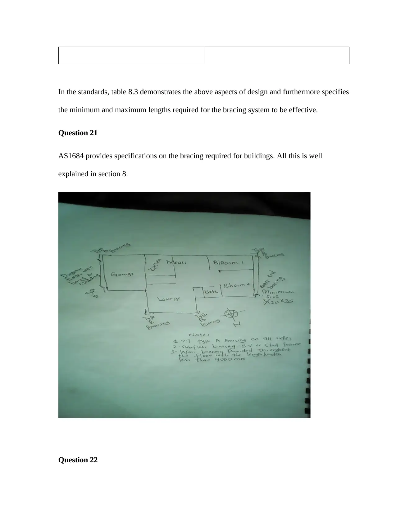
Question 21
AS1684 provides specifications on the bracing required for buildings. All this is well
explained in section 8.
Question 22
the minimum and maximum lengths required for the bracing system to be effective.
Question 21
AS1684 provides specifications on the bracing required for buildings. All this is well
explained in section 8.
Question 22
A) The span of the ceiling joist should be about 2400mm but in this case, it will be
continuous.
B) The span of the hanging beam will be 3000.
C) Using MGP10 ,and a span of 3000mm,the size of the hanging beam may be 140 35mm
Question 23
A) Considering that the maximum length to be covered by the roof is 14.74m.the roof
span may be approximated to be greater than this, therefore, it should be a minimum
of 14740mm.
B) The rafter span may be taken to be 1800mm, seasoned F5 timber.
C) An under purlin is not a requirement since the rafter and all other members ensure
that the roof loads are effectively transferred to the joists.
D) Providing an under purlin at the midspan, the 70 45 MGP10 rafter would be sufficient.
E) The overhang would be 630-450=180mm.All this has been described in calculating the total
rafter length.
F) The overhang is compatible .AS1684 clause 7.2.11.2.
G) The type B bracing units, as per As1684 clause 8.3.2.8 are suitable for the gable end of the
roofs
H) The bracing requirements of trussed roofs can be obtained from Australian building
standards that major on roof construction and design.
⊘ This is a preview!⊘
Do you want full access?
Subscribe today to unlock all pages.
Trusted by 1+ million students worldwide
1 out of 12
Related Documents


Your All-in-One AI-Powered Toolkit for Academic Success.
+13062052269
info@desklib.com
Available 24*7 on WhatsApp / Email
![[object Object]](/_next/static/media/star-bottom.7253800d.svg)
Unlock your academic potential
Copyright © 2020–2026 A2Z Services. All Rights Reserved. Developed and managed by ZUCOL.