Physics Lab Work: Analysis of Resistors and Circuit Behavior

Verified

Added on  2020/05/16

|21
|1576
|140
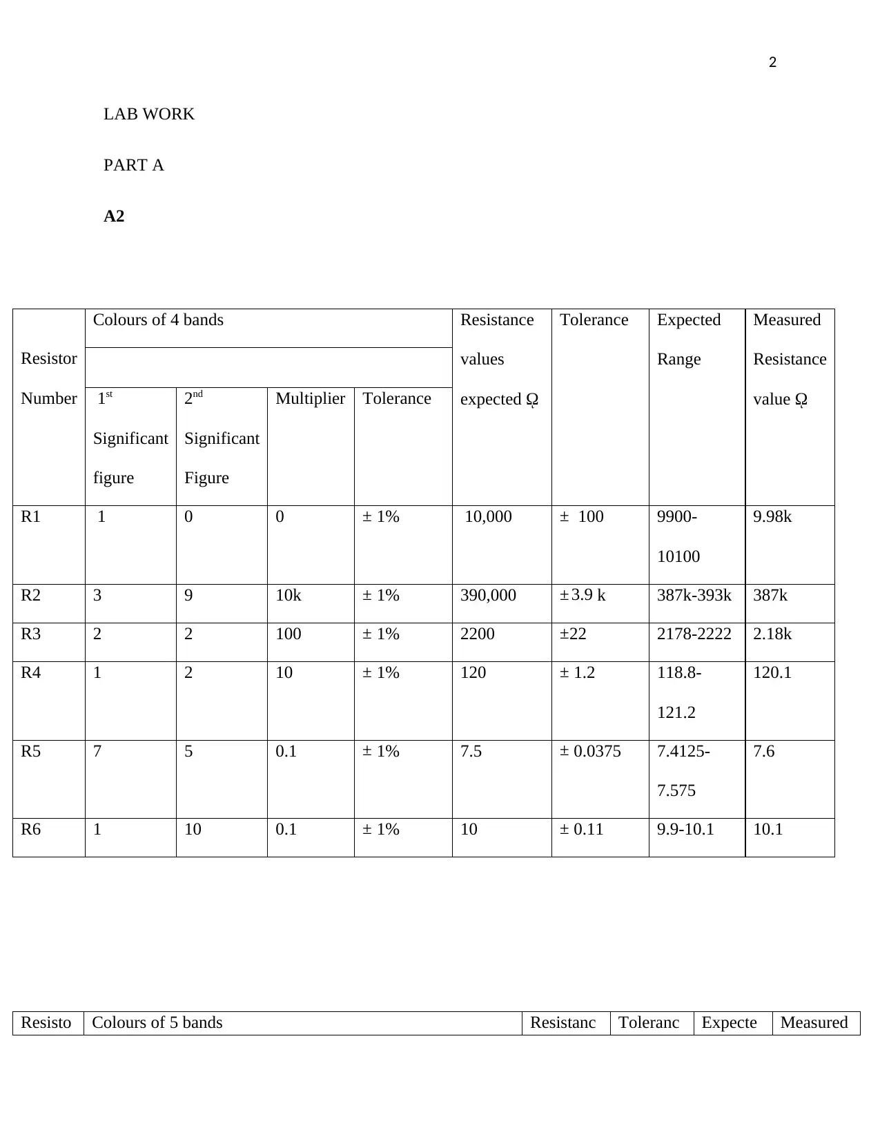
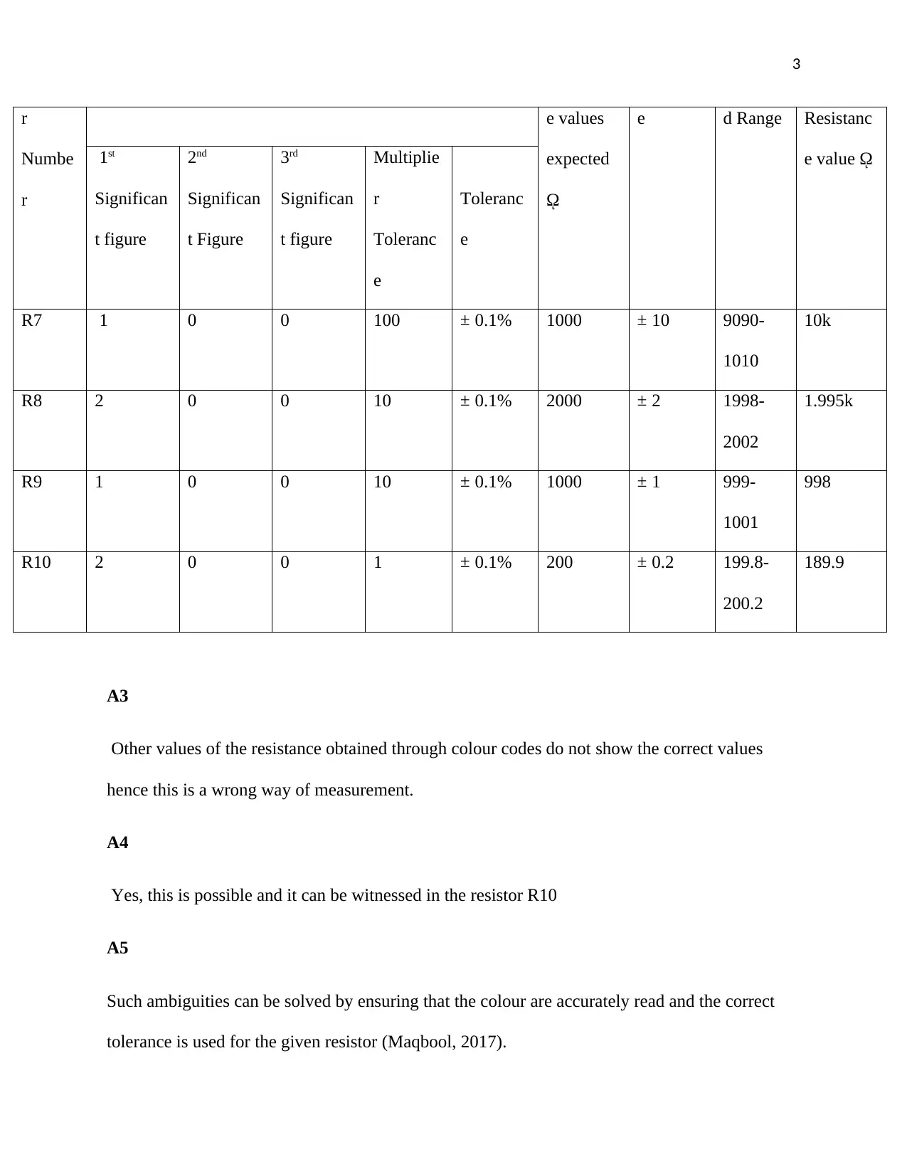
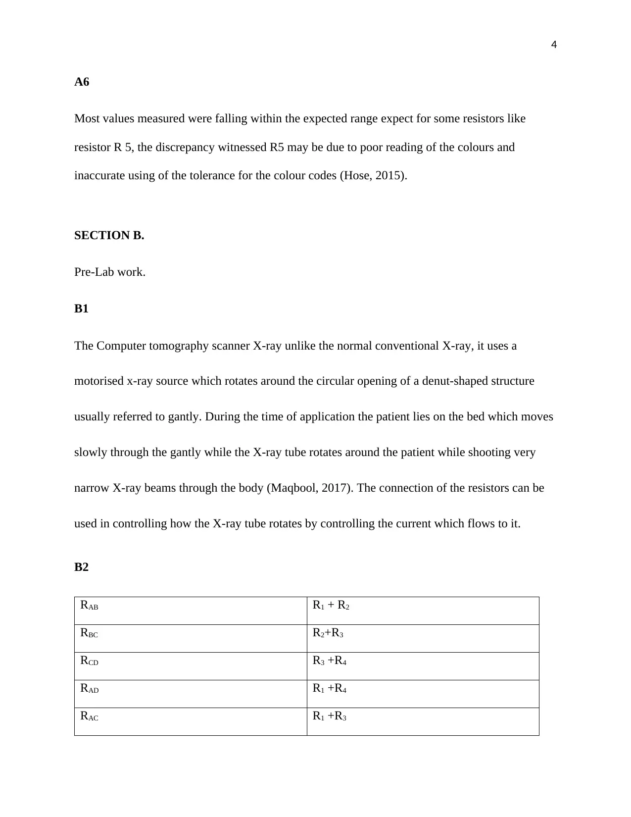
Practical Assignment
AI Summary
This physics lab report encompasses a comprehensive analysis of resistors and circuits, including practical experiments and theoretical calculations. The lab work begins with an examination of resistor color codes, comparing expected and measured resistance values, and identifying potential discrepancies. It then delves into pre-lab work, focusing on the application of resistors in X-ray technology and circuit analysis using series and parallel combinations. The report further explores circuit calculations, including voltage and resistance in various configurations, and examines the behavior of triangular elements in circuits. The analysis includes both theoretical predictions and experimental measurements, with a focus on understanding the relationship between voltage, resistance, and current in different circuit setups. The report also addresses methods for ensuring accurate measurements and troubleshooting common issues in circuit analysis. This assignment provides a detailed exploration of fundamental concepts in electrical circuits and their practical applications.
Document Page
1
PHYSICS WITH MEDICAL PHYSICS
Name of Student
Institution Affiliation
tabler-icon-diamond-filled.svg

Paraphrase This Document

Need a fresh take? Get an instant paraphrase of this document with our AI Paraphraser
Document Page
2
LAB WORK
PART A
A2
Resistor
Number
Colours of 4 bands Resistance
values
expected ῼ
Tolerance Expected
Range
Measured
Resistance
value ῼ1st
Significant
figure
2nd
Significant
Figure
Multiplier Tolerance
R1 1 0 0 ± 1% 10,000 ± 100 9900-
10100
9.98k
R2 3 9 10k ± 1% 390,000 ± 3.9 k 387k-393k 387k
R3 2 2 100 ± 1% 2200 ±22 2178-2222 2.18k
R4 1 2 10 ± 1% 120 ± 1.2 118.8-
121.2
120.1
R5 7 5 0.1 ± 1% 7.5 ± 0.0375 7.4125-
7.575
7.6
R6 1 10 0.1 ± 1% 10 ± 0.11 9.9-10.1 10.1
Resisto Colours of 5 bands Resistanc Toleranc Expecte Measured
Document Page
3
r
Numbe
r
e values
expected

e d Range Resistanc
e value ῼ1st
Significan
t figure
2nd
Significan
t Figure
3rd
Significan
t figure
Multiplie
r
Toleranc
e
Toleranc
e
R7 1 0 0 100 ± 0.1% 1000 ± 10 9090-
1010
10k
R8 2 0 0 10 ± 0.1% 2000 ± 2 1998-
2002
1.995k
R9 1 0 0 10 ± 0.1% 1000 ± 1 999-
1001
998
R10 2 0 0 1 ± 0.1% 200 ± 0.2 199.8-
200.2
189.9
A3
Other values of the resistance obtained through colour codes do not show the correct values
hence this is a wrong way of measurement.
A4
Yes, this is possible and it can be witnessed in the resistor R10
A5
Such ambiguities can be solved by ensuring that the colour are accurately read and the correct
tolerance is used for the given resistor (Maqbool, 2017).
Document Page
4
A6
Most values measured were falling within the expected range expect for some resistors like
resistor R 5, the discrepancy witnessed R5 may be due to poor reading of the colours and
inaccurate using of the tolerance for the colour codes (Hose, 2015).
SECTION B.
Pre-Lab work.
B1
The Computer tomography scanner X-ray unlike the normal conventional X-ray, it uses a
motorised x-ray source which rotates around the circular opening of a denut-shaped structure
usually referred to gantly. During the time of application the patient lies on the bed which moves
slowly through the gantly while the X-ray tube rotates around the patient while shooting very
narrow X-ray beams through the body (Maqbool, 2017). The connection of the resistors can be
used in controlling how the X-ray tube rotates by controlling the current which flows to it.
B2
RAB R1 + R2
RBC R2+R3
RCD R3 +R4
RAD R1 +R4
RAC R1 +R3
tabler-icon-diamond-filled.svg

Paraphrase This Document

Need a fresh take? Get an instant paraphrase of this document with our AI Paraphraser
Document Page
5
RBD R2 +R4
B3
RAB = R1 + R2
RBC = R2+R3
RCD = R3 +R4
RAD = R1 +R4
RAC = R1 +R3
RBD = R2 +R4
Solving simultaneously;
R1= R2 - RAB
R4 = R2 - RBD
R1 = (R3 - RBC) - RAB
R2 = R3 - RBC
R2 = (R4 - RCD)- RBC
R3 = R4 - RCD
R3 = (R2 - RBD) - RCD
R4 = R2 - RBD
R4 = R2 - RBD
Document Page
6
R4 = (R3 - RBC) - RBD
B4
Phantom X Phantom Y
RAB 4 Ω 3Ω
RBC 3 Ω
RCD 4 Ω 5Ω
RAC 3Ω
RAD 4Ω 5Ω
RBD 3Ω 2Ω
B5
RAB = 4 Ω
RBC = 3 Ω
RCD = 4 Ω
RAC =
RAD = 4Ω
RBD = 3Ω
R1 = (RCD - RBC) + RAB
= 4 Ω - 3 Ω + 4Ω
Document Page
7
R1 = 5 Ω
R2 = (RBC + RCD) - RAB
=3 Ω + 4 Ω - 4 Ω
R2 = 3 Ω
R3 = (RBC - RBD) + RCD
R3 = 3 Ω - 3Ω +4 Ω
=4 Ω
R4 = (RCD + RBC) - RBD
R4= 4 Ω + 3 Ω - 3Ω
=4 Ω
B6
R1 = (RCD - RBC) + RAB
R1 = 5Ω - 4Ω + 3Ω
R1= 4Ω
tabler-icon-diamond-filled.svg

Paraphrase This Document

Need a fresh take? Get an instant paraphrase of this document with our AI Paraphraser
Document Page
8
R2 = (RBC + RCD) - RAB
= 4Ω + 5Ω -3Ω
= 6Ω
R3 = (RBC - RBD) + RCD
=4Ω - 5Ω
= 5Ω
R4 = (RCD + RBC) - RBD
=5Ω + 4Ω -2Ω
= 7 Ω
B7
RAB = RW.(RX +RY +RZ)
RW + RX + RY + RZ
RBC =RX.( RW +RY +RZ)
RX + RW+ RY + RZ
RCD = RY.( RW +RX +RZ)
RY + RW+ RX + RZ
Document Page
9
RAD = RZ.( RW +RX +RY
RZ + RW+ RX + RY
RAC =RX.( RW +RY +RZ)
RX + RW+ RY + RZ
RCD = RX.( RW +RY +RZ)
RY + RW+ RX + RZ
B9
Document Page
10
tabler-icon-diamond-filled.svg

Paraphrase This Document

Need a fresh take? Get an instant paraphrase of this document with our AI Paraphraser
Document Page
11
B10
Ensuring a good test.
First one is required to test the resistance on the components and not in the test in the circuit.
Once the resistance of a component is measured while in the circuit there is a great possibility of
getting in correct data (Hose, 2015).
Only the components which are turned off are to be tested.
Document Page
12
All the capacitors in the circuit which are to be tested should be discharged before testing. The
discharged capacitors can absorb charge from the multimeter’s current which will result in a
momentary fluctuations of the results.
One should check for the diodes in the circuit. And determine the resistance which is recorded.
B11
Phantom z
RAB 3 Ω
RBC 6Ω
RCD 4 Ω
RAC 3 Ω
RAD 4 Ω
RBD 3 Ω
B12
R1 = (RCD - RBC) + RAB
= 4 Ω - 3 Ω + 4Ω
R1 = 5 Ω
R2 = (RBC + RCD) - RAB
=3 Ω + 4 Ω - 4 Ω
chevron_up_icon
1 out of 21
circle_padding
hide_on_mobile
zoom_out_icon
[object Object]