COIT20248 - Information System Analysis and Design: RME Report

Verified

Added on  2022/11/09

|22
|2221
|242
Report
AI Summary
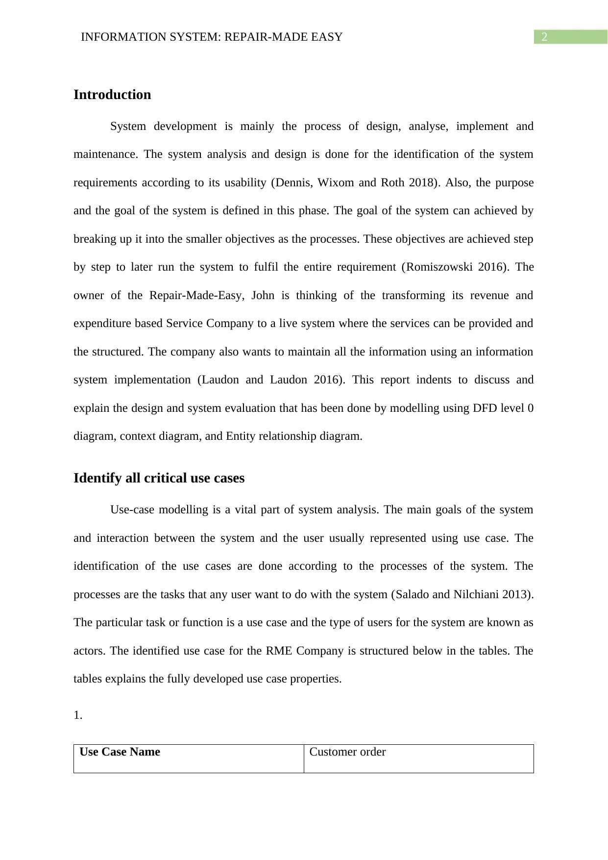
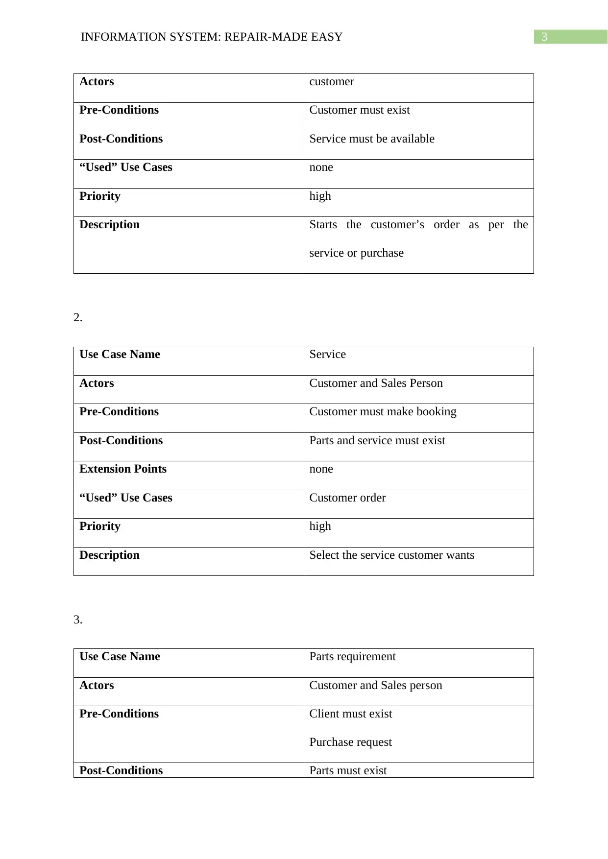
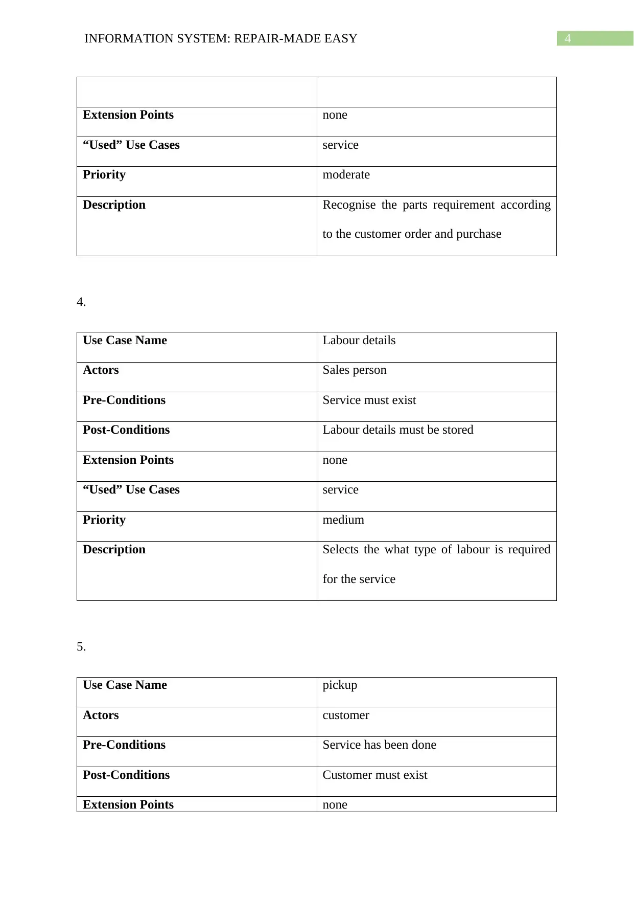
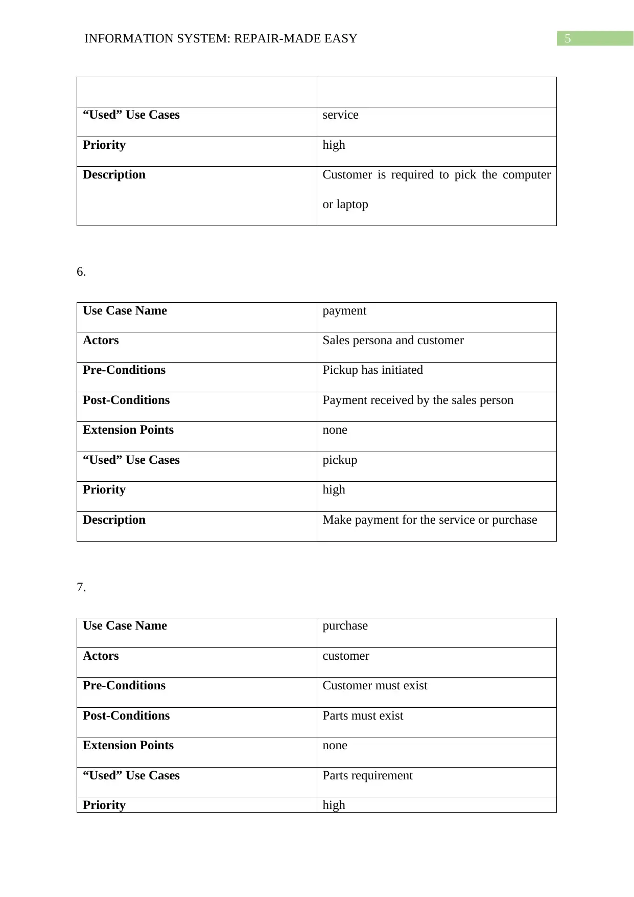
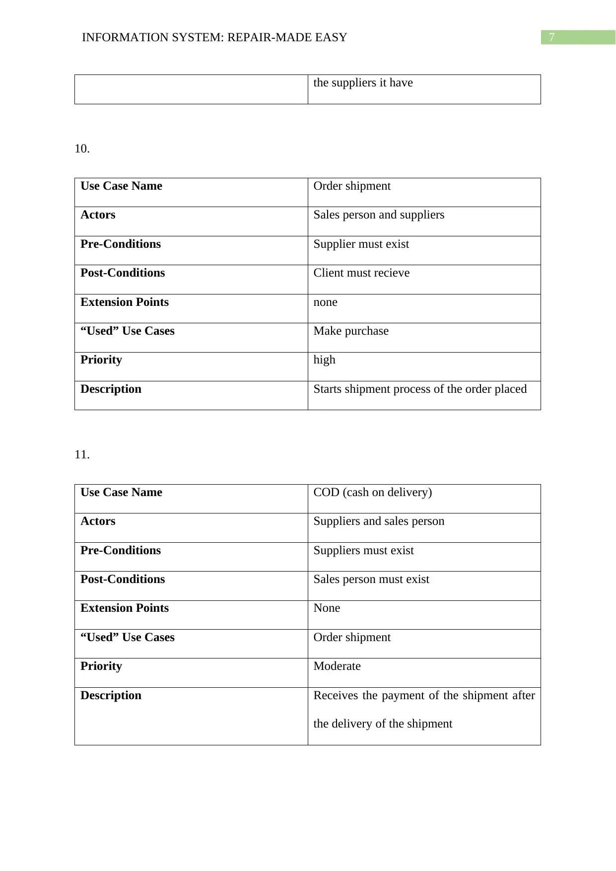
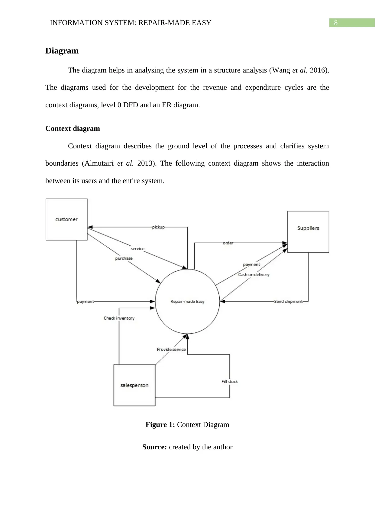
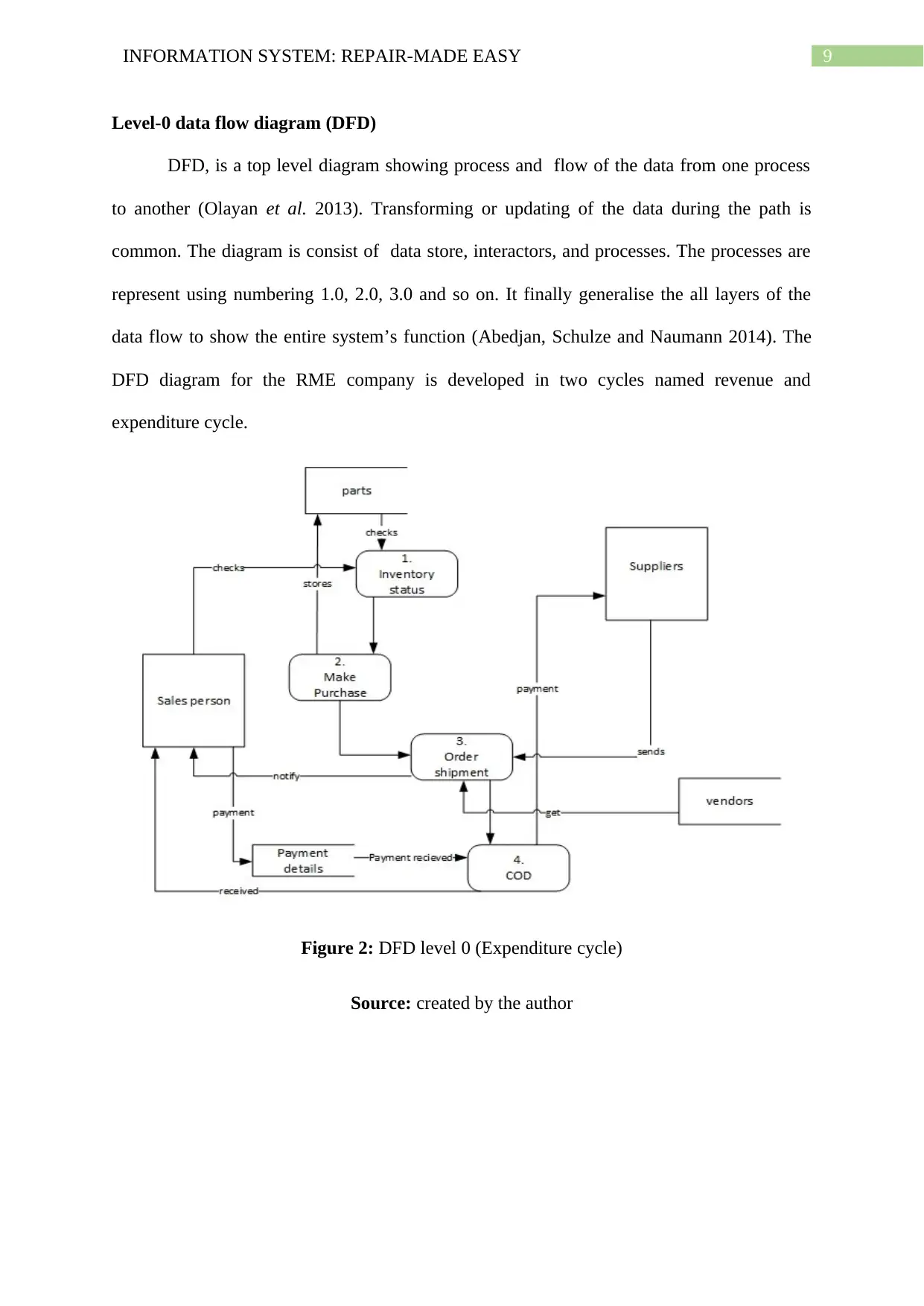
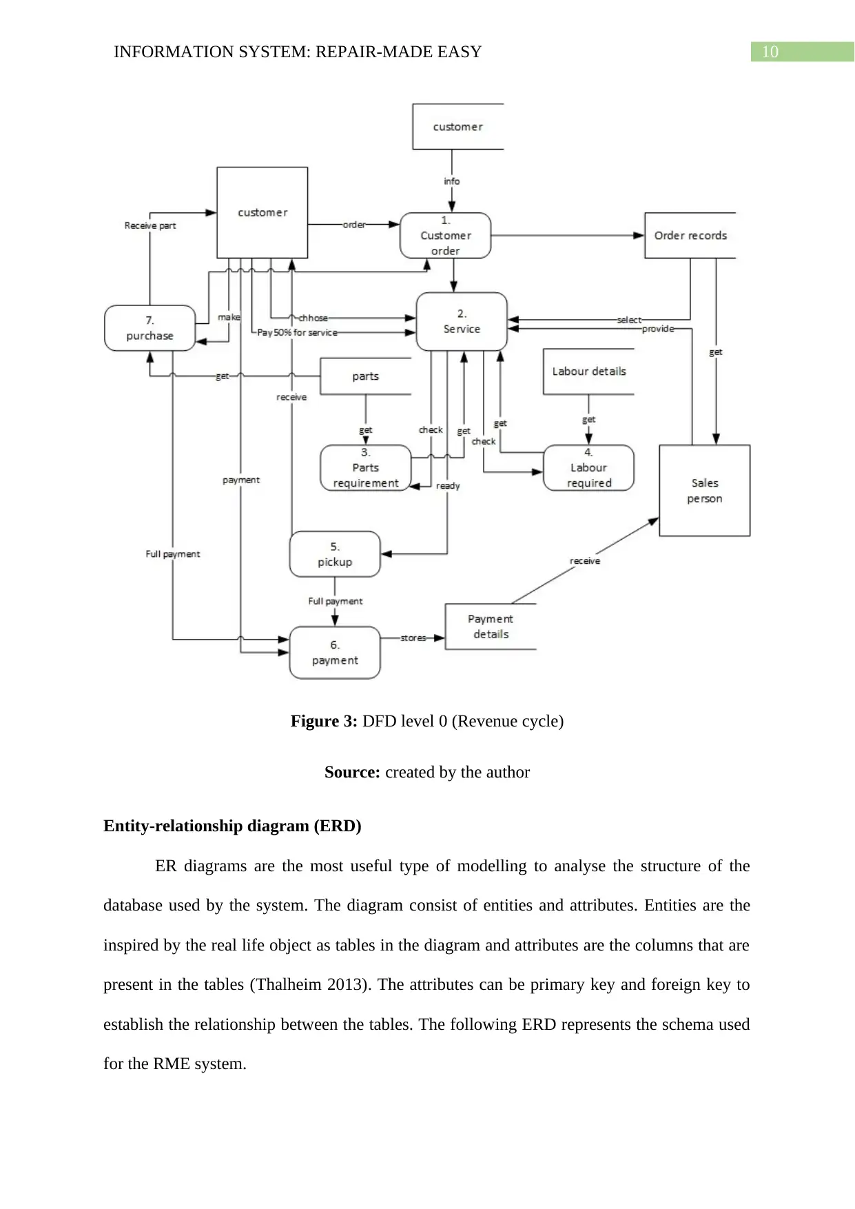
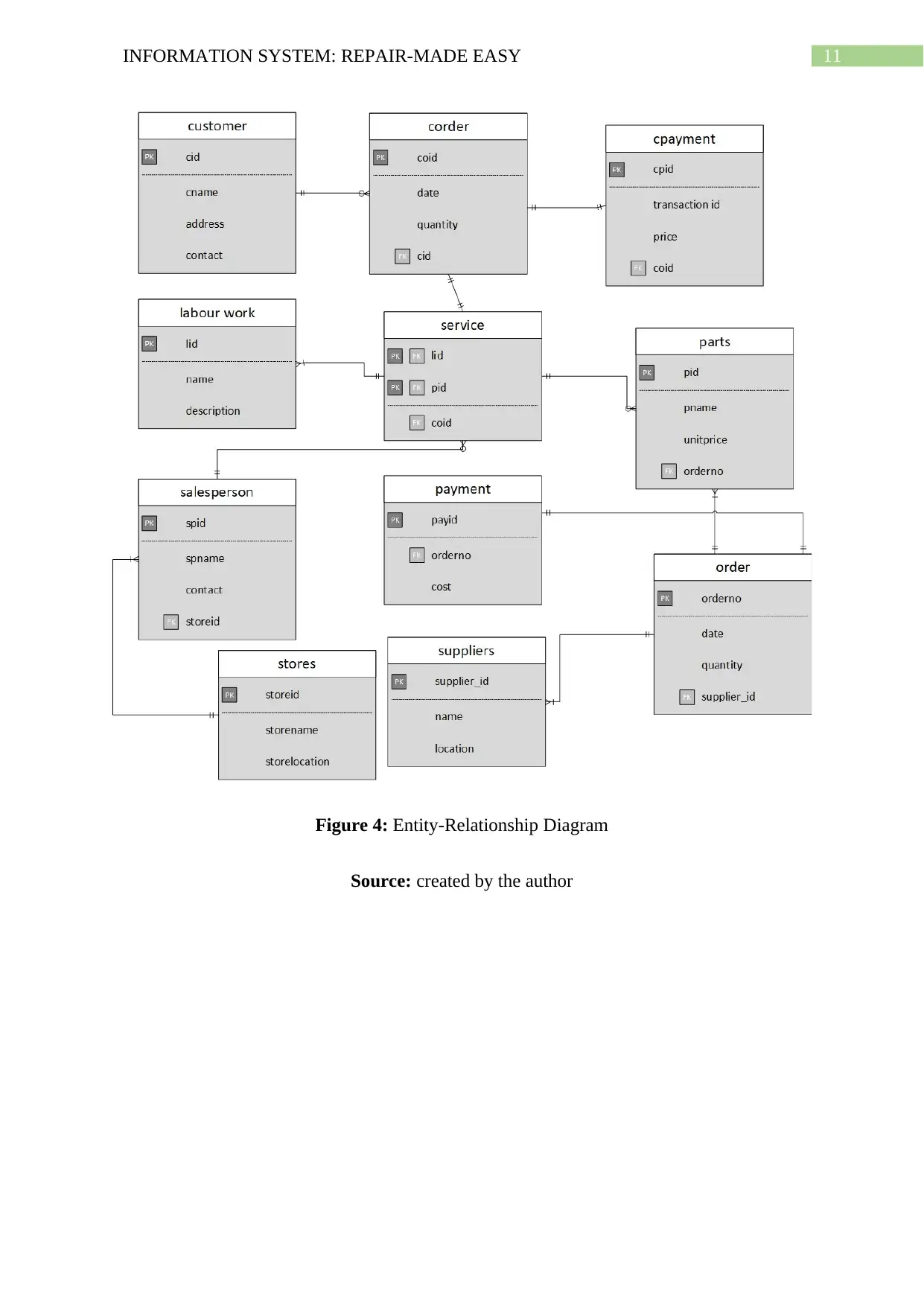
This report presents a comprehensive system analysis and design for Repair-Made-Easy (RME), a service company seeking to implement an information system. The analysis includes the identification of critical use cases, crucial for understanding system interactions and user needs. The report then details the creation of system diagrams, including a context diagram, level-0 data flow diagrams (DFDs) for both revenue and expenditure cycles, and an entity-relationship diagram (ERD) to model the database structure. Data elements required for the system are clearly defined, followed by a CRUD (Create, Read, Update, Delete) diagram illustrating data operations. A prototype of the website design and architecture is also provided, offering a visual representation of the user interface. Finally, the report includes details on individual group member contributions and concludes with a summary of the system design and analysis process, emphasizing the successful completion of the project's objectives. The report utilizes various system analysis and design tools and techniques to provide a holistic overview of the RME information system.
Document Page
Running head: INFORMATION SYSTEM: REPAIR-MADE EASY
Information System: Repair-Made Easy
Name of the Student
Name of the University
Author Note
tabler-icon-diamond-filled.svg

Paraphrase This Document

Need a fresh take? Get an instant paraphrase of this document with our AI Paraphraser
Document Page
1INFORMATION SYSTEM: REPAIR-MADE EASY
Table of Contents
Introduction................................................................................................................................2
Identify all critical use cases......................................................................................................2
Diagram......................................................................................................................................8
Context diagram.....................................................................................................................8
Level-0 data flow diagram (DFD)..........................................................................................9
Entity-relationship diagram (ERD)......................................................................................10
Data elements requirement...................................................................................................12
CRUD diagram.....................................................................................................................15
Prototype of website design and architecture...........................................................................16
Contribution.............................................................................................................................18
Conclusion................................................................................................................................19
References................................................................................................................................20
Document Page
2INFORMATION SYSTEM: REPAIR-MADE EASY
Introduction
System development is mainly the process of design, analyse, implement and
maintenance. The system analysis and design is done for the identification of the system
requirements according to its usability (Dennis, Wixom and Roth 2018). Also, the purpose
and the goal of the system is defined in this phase. The goal of the system can achieved by
breaking up it into the smaller objectives as the processes. These objectives are achieved step
by step to later run the system to fulfil the entire requirement (Romiszowski 2016). The
owner of the Repair-Made-Easy, John is thinking of the transforming its revenue and
expenditure based Service Company to a live system where the services can be provided and
the structured. The company also wants to maintain all the information using an information
system implementation (Laudon and Laudon 2016). This report indents to discuss and
explain the design and system evaluation that has been done by modelling using DFD level 0
diagram, context diagram, and Entity relationship diagram.
Identify all critical use cases
Use-case modelling is a vital part of system analysis. The main goals of the system
and interaction between the system and the user usually represented using use case. The
identification of the use cases are done according to the processes of the system. The
processes are the tasks that any user want to do with the system (Salado and Nilchiani 2013).
The particular task or function is a use case and the type of users for the system are known as
actors. The identified use case for the RME Company is structured below in the tables. The
tables explains the fully developed use case properties.
1.
Use Case Name Customer order
Document Page
3INFORMATION SYSTEM: REPAIR-MADE EASY
Actors customer
Pre-Conditions Customer must exist
Post-Conditions Service must be available
“Used” Use Cases none
Priority high
Description Starts the customer’s order as per the
service or purchase
2.
Use Case Name Service
Actors Customer and Sales Person
Pre-Conditions Customer must make booking
Post-Conditions Parts and service must exist
Extension Points none
“Used” Use Cases Customer order
Priority high
Description Select the service customer wants
3.
Use Case Name Parts requirement
Actors Customer and Sales person
Pre-Conditions Client must exist
Purchase request
Post-Conditions Parts must exist
tabler-icon-diamond-filled.svg

Paraphrase This Document

Need a fresh take? Get an instant paraphrase of this document with our AI Paraphraser
Document Page
4INFORMATION SYSTEM: REPAIR-MADE EASY
Extension Points none
“Used” Use Cases service
Priority moderate
Description Recognise the parts requirement according
to the customer order and purchase
4.
Use Case Name Labour details
Actors Sales person
Pre-Conditions Service must exist
Post-Conditions Labour details must be stored
Extension Points none
“Used” Use Cases service
Priority medium
Description Selects the what type of labour is required
for the service
5.
Use Case Name pickup
Actors customer
Pre-Conditions Service has been done
Post-Conditions Customer must exist
Extension Points none
Document Page
5INFORMATION SYSTEM: REPAIR-MADE EASY
“Used” Use Cases service
Priority high
Description Customer is required to pick the computer
or laptop
6.
Use Case Name payment
Actors Sales persona and customer
Pre-Conditions Pickup has initiated
Post-Conditions Payment received by the sales person
Extension Points none
“Used” Use Cases pickup
Priority high
Description Make payment for the service or purchase
7.
Use Case Name purchase
Actors customer
Pre-Conditions Customer must exist
Post-Conditions Parts must exist
Extension Points none
“Used” Use Cases Parts requirement
Priority high
Document Page
6INFORMATION SYSTEM: REPAIR-MADE EASY
Description Purchase the parts directly for home use or
repair
8.
Use Case Name Inventory status
Actors Sales person
Pre-Conditions Sales person must exist
Post-Conditions Parts must exist in inventory
Extension Points None
“Used” Use Cases None
Priority Moderate
Description Checks the status of the parts in inventory
9.
Use Case Name Make purchase
Actors Sales person
Pre-Conditions Sales person must exist
Post-Conditions Suppliers must exist
Extension Points None
“Used” Use Cases Inventory status
Priority High
Description Purchase request from the sales person to
tabler-icon-diamond-filled.svg

Paraphrase This Document

Need a fresh take? Get an instant paraphrase of this document with our AI Paraphraser
Document Page
7INFORMATION SYSTEM: REPAIR-MADE EASY
the suppliers it have
10.
Use Case Name Order shipment
Actors Sales person and suppliers
Pre-Conditions Supplier must exist
Post-Conditions Client must recieve
Extension Points none
“Used” Use Cases Make purchase
Priority high
Description Starts shipment process of the order placed
11.
Use Case Name COD (cash on delivery)
Actors Suppliers and sales person
Pre-Conditions Suppliers must exist
Post-Conditions Sales person must exist
Extension Points None
“Used” Use Cases Order shipment
Priority Moderate
Description Receives the payment of the shipment after
the delivery of the shipment
Document Page
8INFORMATION SYSTEM: REPAIR-MADE EASY
Diagram
The diagram helps in analysing the system in a structure analysis (Wang et al. 2016).
The diagrams used for the development for the revenue and expenditure cycles are the
context diagrams, level 0 DFD and an ER diagram.
Context diagram
Context diagram describes the ground level of the processes and clarifies system
boundaries (Almutairi et al. 2013). The following context diagram shows the interaction
between its users and the entire system.
Figure 1: Context Diagram
Source: created by the author
Document Page
9INFORMATION SYSTEM: REPAIR-MADE EASY
Level-0 data flow diagram (DFD)
DFD, is a top level diagram showing process and flow of the data from one process
to another (Olayan et al. 2013). Transforming or updating of the data during the path is
common. The diagram is consist of data store, interactors, and processes. The processes are
represent using numbering 1.0, 2.0, 3.0 and so on. It finally generalise the all layers of the
data flow to show the entire system’s function (Abedjan, Schulze and Naumann 2014). The
DFD diagram for the RME company is developed in two cycles named revenue and
expenditure cycle.
Figure 2: DFD level 0 (Expenditure cycle)
Source: created by the author
tabler-icon-diamond-filled.svg

Paraphrase This Document

Need a fresh take? Get an instant paraphrase of this document with our AI Paraphraser
Document Page
10INFORMATION SYSTEM: REPAIR-MADE EASY
Figure 3: DFD level 0 (Revenue cycle)
Source: created by the author
Entity-relationship diagram (ERD)
ER diagrams are the most useful type of modelling to analyse the structure of the
database used by the system. The diagram consist of entities and attributes. Entities are the
inspired by the real life object as tables in the diagram and attributes are the columns that are
present in the tables (Thalheim 2013). The attributes can be primary key and foreign key to
establish the relationship between the tables. The following ERD represents the schema used
for the RME system.
Document Page
11INFORMATION SYSTEM: REPAIR-MADE EASY
Figure 4: Entity-Relationship Diagram
Source: created by the author
chevron_up_icon
1 out of 22
circle_padding
hide_on_mobile
zoom_out_icon
[object Object]