Road Design: Horizontal and Vertical Alignment Report Analysis

Verified

Added on  2022/09/18

|6
|1084
|26
Report
AI Summary
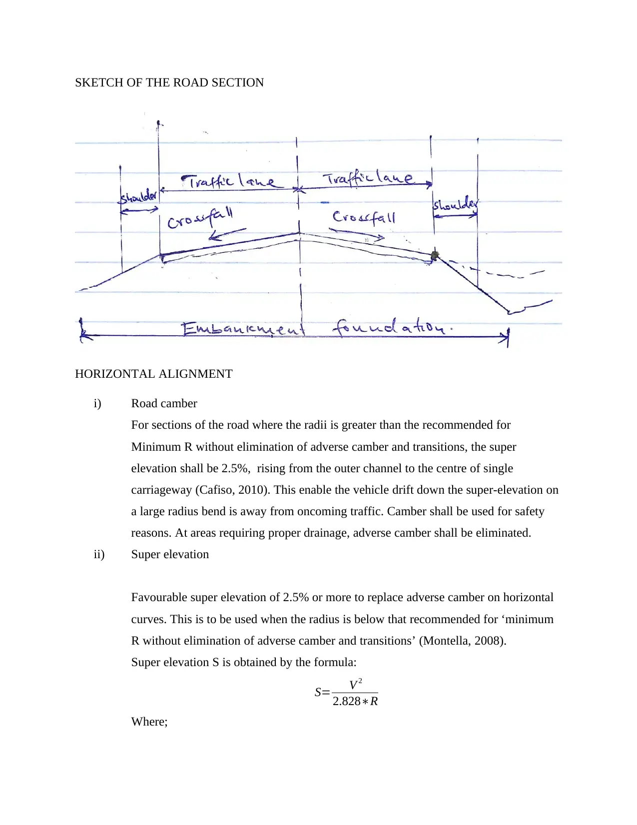
This report presents a detailed analysis of the horizontal and vertical alignment design for a road section. It covers critical aspects such as road camber, super elevation calculations based on design speed and curve radius, and the development length of super elevation. The report also addresses horizontal alignment for cycle facilities, including desirable minimum radii and considerations for tight curves. Furthermore, it examines vertical alignment, including maximum and minimum gradients for motorized vehicles and cycle facilities, along with vertical curve design, k-values, and relaxations in vertical alignment, such as crest and sag curves. References to relevant research papers support the design choices and methodologies employed in this report.
Document Page
SKETCH OF THE ROAD SECTION
HORIZONTAL ALIGNMENT
i) Road camber
For sections of the road where the radii is greater than the recommended for
Minimum R without elimination of adverse camber and transitions, the super
elevation shall be 2.5%, rising from the outer channel to the centre of single
carriageway (Cafiso, 2010). This enable the vehicle drift down the super-elevation on
a large radius bend is away from oncoming traffic. Camber shall be used for safety
reasons. At areas requiring proper drainage, adverse camber shall be eliminated.
ii) Super elevation
Favourable super elevation of 2.5% or more to replace adverse camber on horizontal
curves. This is to be used when the radius is below that recommended for ‘minimum
R without elimination of adverse camber and transitions’ (Montella, 2008).
Super elevation S is obtained by the formula:
S= V 2
2.828R
Where;
tabler-icon-diamond-filled.svg

Paraphrase This Document

Need a fresh take? Get an instant paraphrase of this document with our AI Paraphraser
Document Page
R is the radius of curve in metres.
V is the design speed in km/h.
The design speed is 100 km/h and the radius of curve of 1000 m (assumed).
Thus, super elevation S will be;
S= 1002
2.8281000 =3.5 %
The super elevation obtained is adequate because it is below 7%.
Super elevation development length Le is obtained from Austroads table 7.11 and
obtained by the formula:
Le=100 W e2e1
Gr
Where;
W is the maximum width from axis of rotation to edge of running lane in m.
Gr is the allowable relative grade.
e1 ,e2 are super elevation at ends of development length.
From the road design manual, Gr = 0.7 for two lanes, W = 3m , e1=3.5 % and
e2=3.5 %. Substituting the values we get;
Le= 10033.53.5
0.7 =3000 m
iii) Horizontal alignment for cycle facilities
Sufficient horizontal radii shall be provided to ensure that safety and comfort-ability
is achieved while cycling. The horizontal radii must be large enough to allow the
cyclist to keep balance as well as maintaining momentum while approaching the
curve. Tight horizontal radii interferes with the safety and aesthetic value of the cycle
facility.
Tight horizontal radii shall be used in major junctions to act as speed inhibitor.
Warning signs and traffic indicators must be erected in this regions.
iv) Desirable minimum Radius
From the value of super elevation of 3.5% obtained, the desirable minimum radii
shall be 1020 m.
v) Relaxations in Horizontal alignment
Document Page
There will be 3 design speed step since the road is type 2 single carriageway. There
shall be a reduction of one design speed step proximately succeeding an overtaking
section (Lord, 2007).
vi) Widening on Curves
On low radius curves, pavement widening shall be done at curves on lines and
junctions to permit swept path of heavy/long automobiles.
For 50 m curve radius, we use 4.65 m minimum lane width along the curve.
vii) Coordinates and distances.
Coordinates of the intersections will be as follows;
Angle between IP2 and IP1 is as:
θ1=tan1
( 4350042650
9550096750 )=34.220
Angle between IP3 and IP2 is as:
θ2=tan1
( 4265041840
9675097900 )=35.160
Angle between IP4 and IP3 is as:
θ1=tan1
( 4100041840
9910097900 )=34.990
Distance between the intersections will be as follows;
Distance between IP1 and IP2 will be;
x1= 115112.5
sin34.220 =4.445 km
Distance between IP2 and IP3 will be;
x2= 116112.5
sin 35.160 =6.078 km
Distance between IP3 and IP4 will be;
x3= 143116
sin 34.990 =47.08 km
Document Page
viii) Chainages
Chainage Sub
Chord
EDM Coordinates Deflection
East North Mins
0 0 0 0 0 0 0
1194.5 1194.5 1124.6 632.4 929.9 2053.2 340 13 ' 12 ' '
2421.8 2421.8 1871.9 1752 659.2 4162.8 690 22' 48 ' '
3643.2 3643.2 1937.4 1876.8 -480.9 6262.3 1040 22 ' 10 ' '
VERTICAL ALIGNMENT
i) Gradients for Motorised Vehicles
a) Maximum Gradients
Will be obtained from the table below:
Desirable Maximum Grade
Type 1 dual carriageway 3%
Type 2 and 3 dual carriageway 4%
Type 1 and 2 single carriageway 5%
Type 3 single carriageway 6%
Other local roads 7%
The road under design is type 2 single carriageway and thus will have a desirable
maximum grade of 5%.
In hilly regions, steeper gradients will be used.
b) Minimum Gradient
A minimum gradient of 1% will be maintained to improve drainage. For gently
sloping regions, vertical alignment should be unchanged. Vertical curvature shall
tabler-icon-diamond-filled.svg

Paraphrase This Document

Need a fresh take? Get an instant paraphrase of this document with our AI Paraphraser
Document Page
not be introduced. Kerb and drainage system of minimum gradients of 1% shall
be used to provide longitudinal drainage paths.
ii) Gradients for cycle facilities
Shallow gradient shall be used on cycle facilities to promote comfort and aesthetic
values.
A gradient of 5% shall be used.
iii) Vertical curves
All changes in gradient shall be accompanied by vertical curves. It must be able to
offer comfort and sufficient sight distance for safety purposes. Stopping sight distance
must also be appropriate to enable safe stopping (Bella, 2013).
A. K values
The k values for 100 km/h will be as follows:
Desirable minimum crest K value = 182
One step below desirable minimum crest K value = 100
The length of crust curve will be:
Desirable Min = 182 * 3.5 = 637 m
One step below desirable minimum = 100 * 3.5 = 350 m.
iv) Relaxations in Vertical Alignment
a) Crest Curves
2 design speed steps shall be used.
For sections exceeding 1.5 km with a gradient of more than 4%, one additional
design speed step shall be used. This will have a large impact on reduced velocity
uphill.
b) Sag curves
Two deign speed steps below the desirable minimum will be acceptable.
However, this will not be acceptable on the immediate approaches to junctions.
References
Document Page
Bella, F., 2013. Driver perception of roadside configurations on two-lane rural roads: Effects on
speed and lateral placement. Accident Analysis & Prevention, 50, pp.251-262.
Cafiso, S., Di Graziano, A., Di Silvestro, G., La Cava, G. and Persaud, B., 2010. Development of
comprehensive accident models for two-lane rural highways using exposure, geometry,
consistency and context variables. Accident Analysis & Prevention, 42(4), pp.1072-1079.
Lord, D. and Bonneson, J.A., 2007. Development of accident modification factors for rural
frontage road segments in Texas. Transportation Research Record, 2023(1), pp.20-27.
Montella, A., Colantuoni, L. and Lamberti, R., 2008. Crash prediction models for rural
motorways. Transportation Research Record, 2083(1), pp.180-189.
chevron_up_icon
1 out of 6
circle_padding
hide_on_mobile
zoom_out_icon
[object Object]