Research Project: Line Tracer Robotic Car Design and Implementation
VerifiedAdded on 2023/06/05
|42
|6741
|146
Project
AI Summary
This research project details the design and implementation of a line tracer robotic car, aimed at automating transportation in various environments such as hospitals and industries. The project proposes an autonomous system that utilizes IR sensors to detect a predefined black line on a white surface, guiding the robot's movement. The design incorporates an Arduino UNO microcontroller as the central processing unit, controlling the robot's actions based on sensor input. Key components include the chassis, DC brushed motors, a motor driver, and a power supply. The methodology involves defining system aims, objectives, and key concepts, along with a comprehensive review of hardware and software requirements. The hardware section elaborates on the selection and function of the microcontroller, chassis, sensors (specifically IR sensors), actuators, motor drivers, and the power supply. The software section focuses on the Arduino UNO software and Proteus for simulation. The project also includes a literature review, design considerations, and future scope, concluding with a discussion of the robot's functionality, including its ability to navigate turns and stop at designated points. The project emphasizes the potential of robotics to improve efficiency and reliability in goods transportation, addressing the limitations of manual processes.
Research Project 1
RESEARCH PROJECT
By Name
Course
Instructor
Institution
Location
Date
RESEARCH PROJECT
By Name
Course
Instructor
Institution
Location
Date
Paraphrase This Document
Need a fresh take? Get an instant paraphrase of this document with our AI Paraphraser
Research Project 2
ABSTRACT
A quick tour to most industries, hospitals and hotels will expose the
vulnerability in goods delivery experienced in the mentioned areas.
Autonomous goods delivery therefore becomes essential to enhance efficient
transportation of goods or equipment to the required destination. The
manual form of transportation involving humans leads to delays, monotony
and even fatigue when heavy goods are to be conveyed. This study proposes
a line following robot that can detect and follow a line drawn on the floor.
The pre-defined path will be a black line on a white surface. The robot follows
the line using Infra-Red Ray sensors installed under the robot at the front
end. The sensors detect the line position and the read data is transmitted to
the microcontroller which then controls the robot to move straight, left or
right by use of a motor driver. The speed of the robot will be controlled
according to the lane condition which means that for a curvy lane, the speed
of the robot is decreased in order to obtain a smooth turn.
Table of Contents
ABSTRACT........................................................................................................2
Research Project 3
TOPIC OF THE PROPOSAL.................................................................................5
INTRODUCTION................................................................................................5
AIM OF THE PROPOSAL....................................................................................6
System Aims.................................................................................................6
System Objectives........................................................................................7
DEFINITION OF KEY CONCEPTS........................................................................7
BACKGROUND INFORMATION..........................................................................8
THESIS STATEMENT.........................................................................................9
Problem Statement.......................................................................................9
Proposed Solution.......................................................................................10
RESEARCH METHODOLOGY...........................................................................10
Hardware requirement for the design.........................................................10
Microcontrollers.......................................................................................11
Body and Chassis....................................................................................12
Sensors....................................................................................................13
Actuators.................................................................................................15
Motor driver.............................................................................................16
Power supply...........................................................................................18
Software requirements...............................................................................19
Arduino UNO software.............................................................................19
Proteus....................................................................................................25
⊘ This is a preview!⊘
Do you want full access?
Subscribe today to unlock all pages.
Trusted by 1+ million students worldwide
Research Project 4
Literature Review...........................................................................................26
Design.........................................................................................................26
Driver controller......................................................................................27
Working of the line tracer robotic car............................................................28
The Quadratic Line-Detection Algorithm.....................................................31
Final design....................................................................................................32
Research methods and approaches to primary and secondary research......33
Types of communication approaches to present research outcomes............33
Future scope of the line tracer robotic car.....................................................34
Conclusion.....................................................................................................35
Appendix........................................................................................................40
TOPIC OF THE PROPOSAL
Paraphrase This Document
Need a fresh take? Get an instant paraphrase of this document with our AI Paraphraser
Research Project 5
LINE TRACER ROBOTIC CARS
INTRODUCTION
A line tracing robotic car is really a robot made to trace a way
which is predetermined by the user. This line can be a white path or
dark path on the floor or as complex way inspection plans e.g. drawn
path, good markers and laser direct paths. In arrange to classify these
specific paths, different noticing plans should be used. These tactics
may shift from straightforward taken a toll noticing circuit to
comprehensive vision outlines. The choice of this tactic could be
subordinate upon noticing precision and adaptableness needed. From
a mechanical point of view, line tracer automated car has been
implemented to entirely independent plants.
For this research project, these robots abilities as materials
carrier to provide items from one fabricating put to another where rail,
conveyer and scaffold preparations are not conceivable. Separated
from line taking after cap abilities, these robotic line tracer should to
have the capability to discover connections and select on which
connection to turn and which connection to disregard. To include on to
the complexity of the issues sensor positioning moreover plays a part
in optimizing the execution of the robot for errands said prior. A line
Tracer robotic car with choose- and- situation capabilities are
commonly utilized in fabricating plants.
Research Project 6
They move on an indicated way to choose the components m
designated zones and put them on wanted regions. Fundamentally, a
line taking after the robot could be a self-operating robot which
identifies and takes after a line drained on the floor. So, all in all, it can
be said that Line Tracer car may be a machine which takes after a line,
either a dark line or white line. Essentially there are two sorts of line
tracer robots: one is dark line tracer which takes after dark line and
moment is white line tracer which takes after the white line. Line tracer
really faculties the line and run over it.
AIM OF THE PROPOSAL
System Aims
The complete line following robotic system should be able to generate a
signal upon detection of the robot’s deviation from the desired line
position and send the signal to the microcontroller which then controls the
motor driver to bring the robot back to the pre-defined line.
System Objectives
The complete system should be able to;
i. Follow a black line on a white surface.
ii. Take various degrees of turns.
⊘ This is a preview!⊘
Do you want full access?
Subscribe today to unlock all pages.
Trusted by 1+ million students worldwide
Research Project 7
iii. Stop if the surface is all black.
iv. Be insensitive to environmental factors such as noise and
lighting.
DEFINITION OF KEY CONCEPTS
IR – Infrared
LDR – Light Dependent Resistor
LED – Light Emitting Diode
RF – Radio Frequency
CPU – Central Processing Unit
DC – Direct Current
TTL – Transistor-Transistor Logic
BJT – Bipolar Junction Transistor
MOSFET – Metal-oxide-semi-conductor field-effect transistor
IC – Integrated Circuit
Paraphrase This Document
Need a fresh take? Get an instant paraphrase of this document with our AI Paraphraser
Research Project 8
BACKGROUND INFORMATION
Transportation of goods from one point to another may it be in a
hospital, hotel or even an industry is very vital. The transportation is
carried out every single day by people who at most times are extremely
exhausted especially at the close of the day (Al-Tai, 2015, p. 121). In a
hospital when the patient is supposed to take medication, there might
delay in delivering medicine by the nurse in charge as I experienced two
years ago when I was admitted. For industries, we have heavy and risky
products which need to be carried and they pose a major threat to
workers transporting them may it be by hand or even by pushing a cart.
With the increasing improvement in innovation and research revolving
around robotics, we take advantage of this technology to come up with a
robot which is more efficient and practical (Alipanahi, 2013, p. 1210).
Robotics is a part of engineering and science that deals with the
learning of robots and is intricate with a robot’s building, production,
application and structural disposition. In our day to day interaction with
ants which we strive to emulate we have seen how they usually moves in
a line, tracing an unseen path in look for food or even as they return to
their homes (Bajpai, 2016, p. 764). Human beings also follow defined
paths such as sidewalks on roads to avoid collision either with fellow
humans or even with vehicles which also follow lanes to avoid accidents
(Bany, 2012, p. 751). What about a robot that also follows a line? It would
Research Project 9
just be imitating mother-nature. A robot is basically a control system that
attempts to regulate several positional quantities in order to achieve
physical tasks to emulate the human being. Thus with the help of the line
following robot, it is believed that time and manpower can be saved when
it is largely adopted in various industries (Baker, 2011, p. 982).
THESIS STATEMENT
Problem Statement
Transportation of goods, products or equipment in hotels, hospitals and
industries by people can lead to inefficiency in service delivery as human
beings get tired easily. Unreliability by humans is also a major
shortcoming as sometimes they may get asleep when required to carry
goods from one point to another. Pushing of carts or driving of trucks
which might be repetitive work to the driver might cause a slowdown in
the work as it becomes boring after executing it for a while. Therefore
there is a need to find a solution to the manual transportation which
seems to be inefficient and unreliable (Belmans, 2010, p. 132).
Proposed Solution
This study proposes an automated line following a robotic system to
automate transportation. A line tracker sensor within the robot system
shall monitor the line position of the robot. The system shall keep
comparing the actual line position against the desired line position in
⊘ This is a preview!⊘
Do you want full access?
Subscribe today to unlock all pages.
Trusted by 1+ million students worldwide
Research Project 10
order for the robot to move straight, turn left or turn right in accordance
with the pre-defined line to be followed.
RESEARCH METHODOLOGY
Hardware requirement for the design
i. Microcontrollers
ii. Arduino UNO module
iii. DC brushed motors
iv. IR sensor
v. Motor Driver
vi. Source of power
The design of the line tracer robotic car involves several parameters and
components, some of the components which will be employed in the
design of this project are:
Microcontrollers
These are compact integrated circuits designed to control a specific
operation in an embedded system (Bhatt, 2012, p. 902). A typical
microcontroller constitutes a memory, inputs/ outputs, processors and
peripherals in one single chip. There are several microcontrollers which
can be employed in the design of a line tracer robotic, some of these
microcontrollers includes; PIC (peripheral Integral Controllers), PID
Paraphrase This Document
Need a fresh take? Get an instant paraphrase of this document with our AI Paraphraser
Research Project 11
(proportion, Integral and derivative controllers ), Arduino UNO, Arduino
YUN, Arduino mega, programmable logic controllers among other types of
controllers. In this specific project, we will employ the use of Arduino UNO
as our microcontroller.
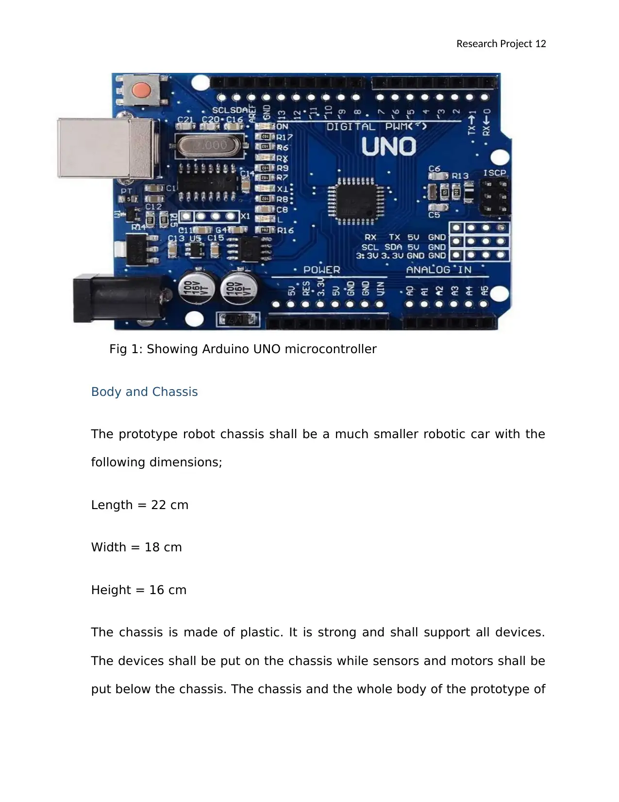
Arduino microcontroller is preferred in this design because it is
relatively easy to program as compared to other types of
microcontrollers. Arduino Uno R3 based on Atmega 328P has been
chosen as it contain fourteen digital output/ input pins, 6 analogue I/Ps, a
16 MHZ quartz crystal, a universal Serial Bus linking, a power jack, an
ICSP header and a reset button. The Arduino can be programmed by
merely through joining it to a computer with a cable of USB. The Arduino
controls all the robot's actions (Bilmate, 2013, p. 1210). Basically, the
microcontroller is the brain of the robotic device, it is in the
microcontroller where all the decision will be made hence the robotic car
will follow the line and negotiate corners based on the decision made here
(Bizuayehu, 2014, p. 677).
(proportion, Integral and derivative controllers ), Arduino UNO, Arduino
YUN, Arduino mega, programmable logic controllers among other types of
controllers. In this specific project, we will employ the use of Arduino UNO
as our microcontroller.
Arduino microcontroller is preferred in this design because it is
relatively easy to program as compared to other types of
microcontrollers. Arduino Uno R3 based on Atmega 328P has been
chosen as it contain fourteen digital output/ input pins, 6 analogue I/Ps, a
16 MHZ quartz crystal, a universal Serial Bus linking, a power jack, an
ICSP header and a reset button. The Arduino can be programmed by
merely through joining it to a computer with a cable of USB. The Arduino
controls all the robot's actions (Bilmate, 2013, p. 1210). Basically, the
microcontroller is the brain of the robotic device, it is in the
microcontroller where all the decision will be made hence the robotic car
will follow the line and negotiate corners based on the decision made here
(Bizuayehu, 2014, p. 677).
Research Project 12
Fig 1: Showing Arduino UNO microcontroller
Body and Chassis
The prototype robot chassis shall be a much smaller robotic car with the
following dimensions;
Length = 22 cm
Width = 18 cm
Height = 16 cm
The chassis is made of plastic. It is strong and shall support all devices.
The devices shall be put on the chassis while sensors and motors shall be
put below the chassis. The chassis and the whole body of the prototype of
⊘ This is a preview!⊘
Do you want full access?
Subscribe today to unlock all pages.
Trusted by 1+ million students worldwide
1 out of 42
Your All-in-One AI-Powered Toolkit for Academic Success.
+13062052269
info@desklib.com
Available 24*7 on WhatsApp / Email
![[object Object]](/_next/static/media/star-bottom.7253800d.svg)
Unlock your academic potential
Copyright © 2020–2026 A2Z Services. All Rights Reserved. Developed and managed by ZUCOL.