Analysis of Roller Bearings: Finite Element Analysis Report
VerifiedAdded on 2020/05/28
|10
|1900
|98
Report
AI Summary
This report presents a Finite Element Analysis (FEA) of lightly loaded high-speed roller bearings, focusing on lubricant starvation and slip, which affect bearing life. It explores Hertzian contact stress, deformation, and the influence of cage speed on the bearing-inner race interface. The report discusses linear and nonlinear stress analysis methods, emphasizing the suitability of linear analysis for the presented problem. It covers stress concentrations, limitations of linear FEA, and the importance of considering material properties. The document includes calculations for maximum contact stress, utilizing formulas to determine contact pressure. The conclusion highlights the similarities between the experimental design and numerical/analytical models, suggesting avenues for further exploration into the behavior of bearing elements and the prediction of failure locations. This report is a valuable resource for understanding the application of FEA in mechanical engineering design.
Running head: FINITE ELEMENT ANALYSIS
FINITE ELEMENT ANALYSIS
[Author Name(s), First M. Last, Omit Titles and Degrees]
[Institutional Affiliation(s)]
FINITE ELEMENT ANALYSIS
[Author Name(s), First M. Last, Omit Titles and Degrees]
[Institutional Affiliation(s)]
Paraphrase This Document
Need a fresh take? Get an instant paraphrase of this document with our AI Paraphraser
2
FINITE ELEMENT ANALYSIS
Introduction
Lightly loaded high-speed roller bearings are in most cases prone lubricant starvation and
slip especially at the interface where the inner circle comes into contact with the rollers. The
bearing life of the roller is affected therefore by these two factors, slip and starvation of the
lubricant, as these factors affect the thickness of the film of oil. Of the most important life factor
is the speed of the cage in the estimation of the contact pressure. This is because any
modification that happens to the bearing-inner race interface is affected by the speed at which the
cage moves (Weisenberger, 2013).
Finite Element Analysis
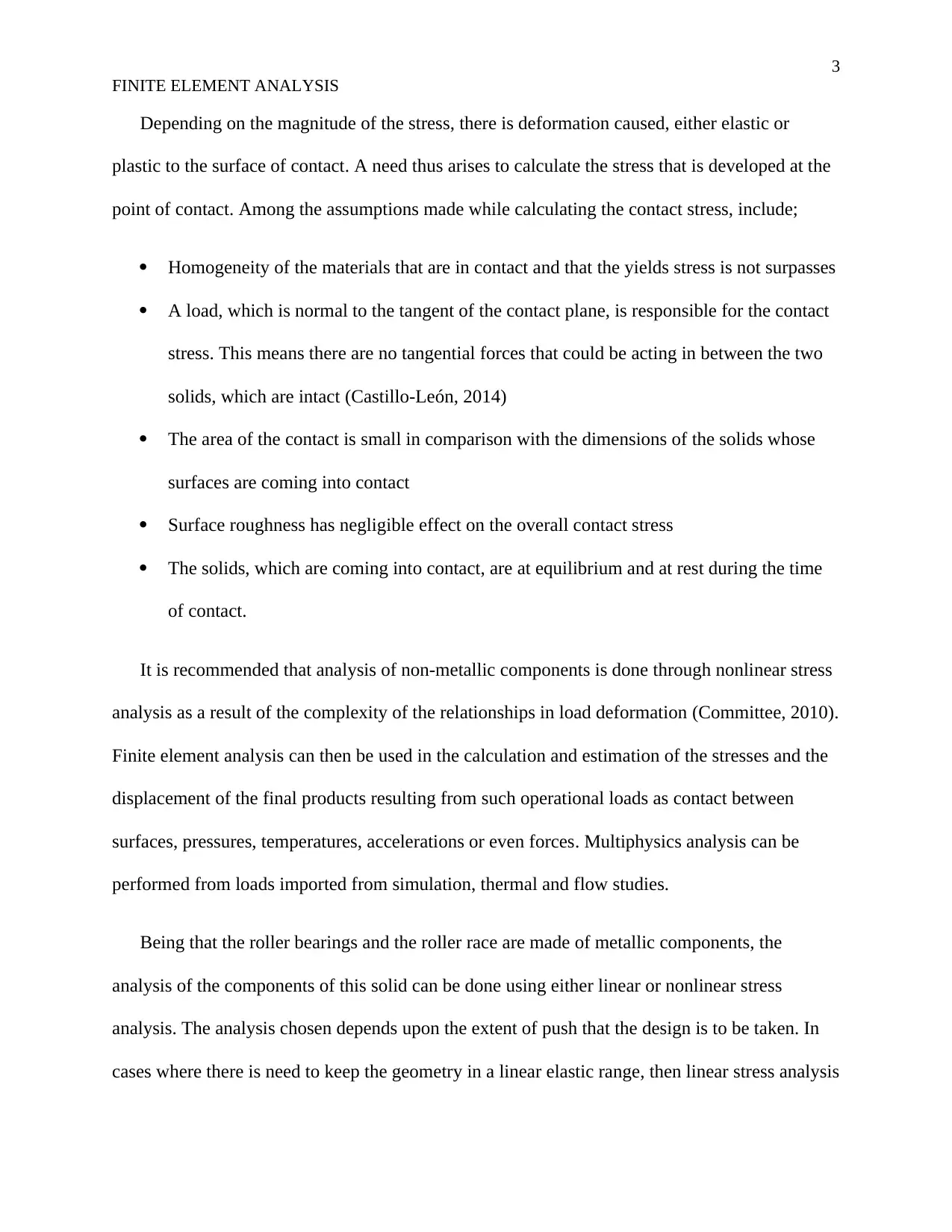
The stress developed when the two surfaces come into contact is defined by Hertzian
contact stress. The extent of deformation on the point of contact when the two surface come
together is dependent on the normal contact force, the elasticity modulus of the two surfaces
coming into contact as well as the radii of curvature of the two surfaces that have come into
contact. Using the equation po = 3. F
2 π a2 , the maximum contact pressure between the two surfaces
can be established (Singh, 2006).
Fig. 1 Points of deformation on the inner circle of the roller
FINITE ELEMENT ANALYSIS
Introduction
Lightly loaded high-speed roller bearings are in most cases prone lubricant starvation and
slip especially at the interface where the inner circle comes into contact with the rollers. The
bearing life of the roller is affected therefore by these two factors, slip and starvation of the
lubricant, as these factors affect the thickness of the film of oil. Of the most important life factor
is the speed of the cage in the estimation of the contact pressure. This is because any
modification that happens to the bearing-inner race interface is affected by the speed at which the
cage moves (Weisenberger, 2013).
Finite Element Analysis
The stress developed when the two surfaces come into contact is defined by Hertzian
contact stress. The extent of deformation on the point of contact when the two surface come
together is dependent on the normal contact force, the elasticity modulus of the two surfaces
coming into contact as well as the radii of curvature of the two surfaces that have come into
contact. Using the equation po = 3. F
2 π a2 , the maximum contact pressure between the two surfaces
can be established (Singh, 2006).
Fig. 1 Points of deformation on the inner circle of the roller
3
FINITE ELEMENT ANALYSIS
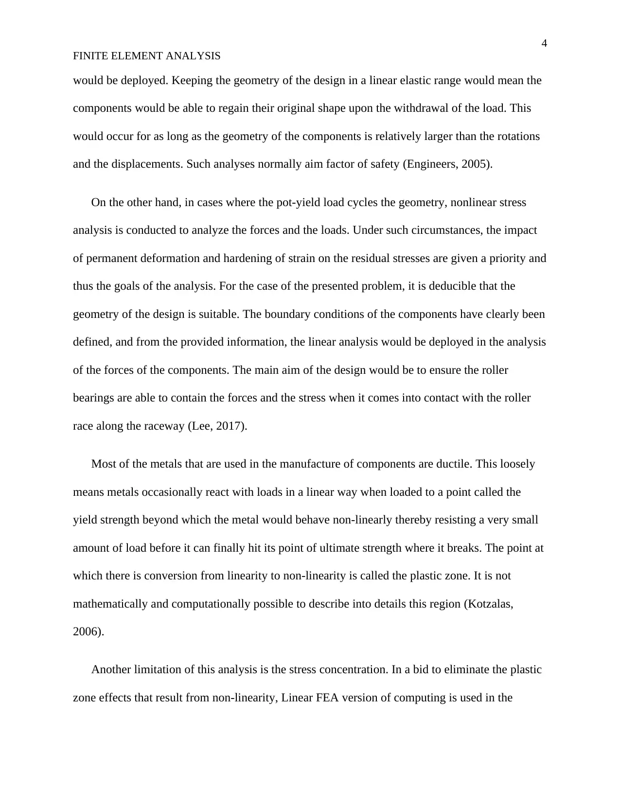
Depending on the magnitude of the stress, there is deformation caused, either elastic or
plastic to the surface of contact. A need thus arises to calculate the stress that is developed at the
point of contact. Among the assumptions made while calculating the contact stress, include;
Homogeneity of the materials that are in contact and that the yields stress is not surpasses
A load, which is normal to the tangent of the contact plane, is responsible for the contact
stress. This means there are no tangential forces that could be acting in between the two
solids, which are intact (Castillo-León, 2014)
The area of the contact is small in comparison with the dimensions of the solids whose
surfaces are coming into contact
Surface roughness has negligible effect on the overall contact stress
The solids, which are coming into contact, are at equilibrium and at rest during the time
of contact.
It is recommended that analysis of non-metallic components is done through nonlinear stress
analysis as a result of the complexity of the relationships in load deformation (Committee, 2010).
Finite element analysis can then be used in the calculation and estimation of the stresses and the
displacement of the final products resulting from such operational loads as contact between
surfaces, pressures, temperatures, accelerations or even forces. Multiphysics analysis can be
performed from loads imported from simulation, thermal and flow studies.
Being that the roller bearings and the roller race are made of metallic components, the
analysis of the components of this solid can be done using either linear or nonlinear stress
analysis. The analysis chosen depends upon the extent of push that the design is to be taken. In
cases where there is need to keep the geometry in a linear elastic range, then linear stress analysis
FINITE ELEMENT ANALYSIS
Depending on the magnitude of the stress, there is deformation caused, either elastic or
plastic to the surface of contact. A need thus arises to calculate the stress that is developed at the
point of contact. Among the assumptions made while calculating the contact stress, include;
Homogeneity of the materials that are in contact and that the yields stress is not surpasses
A load, which is normal to the tangent of the contact plane, is responsible for the contact
stress. This means there are no tangential forces that could be acting in between the two
solids, which are intact (Castillo-León, 2014)
The area of the contact is small in comparison with the dimensions of the solids whose
surfaces are coming into contact
Surface roughness has negligible effect on the overall contact stress
The solids, which are coming into contact, are at equilibrium and at rest during the time
of contact.
It is recommended that analysis of non-metallic components is done through nonlinear stress
analysis as a result of the complexity of the relationships in load deformation (Committee, 2010).
Finite element analysis can then be used in the calculation and estimation of the stresses and the
displacement of the final products resulting from such operational loads as contact between
surfaces, pressures, temperatures, accelerations or even forces. Multiphysics analysis can be
performed from loads imported from simulation, thermal and flow studies.
Being that the roller bearings and the roller race are made of metallic components, the
analysis of the components of this solid can be done using either linear or nonlinear stress
analysis. The analysis chosen depends upon the extent of push that the design is to be taken. In
cases where there is need to keep the geometry in a linear elastic range, then linear stress analysis
⊘ This is a preview!⊘
Do you want full access?
Subscribe today to unlock all pages.
Trusted by 1+ million students worldwide
4
FINITE ELEMENT ANALYSIS
would be deployed. Keeping the geometry of the design in a linear elastic range would mean the
components would be able to regain their original shape upon the withdrawal of the load. This
would occur for as long as the geometry of the components is relatively larger than the rotations
and the displacements. Such analyses normally aim factor of safety (Engineers, 2005).
On the other hand, in cases where the pot-yield load cycles the geometry, nonlinear stress
analysis is conducted to analyze the forces and the loads. Under such circumstances, the impact
of permanent deformation and hardening of strain on the residual stresses are given a priority and
thus the goals of the analysis. For the case of the presented problem, it is deducible that the
geometry of the design is suitable. The boundary conditions of the components have clearly been
defined, and from the provided information, the linear analysis would be deployed in the analysis
of the forces of the components. The main aim of the design would be to ensure the roller
bearings are able to contain the forces and the stress when it comes into contact with the roller
race along the raceway (Lee, 2017).
Most of the metals that are used in the manufacture of components are ductile. This loosely
means metals occasionally react with loads in a linear way when loaded to a point called the
yield strength beyond which the metal would behave non-linearly thereby resisting a very small
amount of load before it can finally hit its point of ultimate strength where it breaks. The point at
which there is conversion from linearity to non-linearity is called the plastic zone. It is not
mathematically and computationally possible to describe into details this region (Kotzalas,
2006).
Another limitation of this analysis is the stress concentration. In a bid to eliminate the plastic
zone effects that result from non-linearity, Linear FEA version of computing is used in the
Paraphrase This Document
Need a fresh take? Get an instant paraphrase of this document with our AI Paraphraser
5
FINITE ELEMENT ANALYSIS
simulation exercise. This version assumes that all materials used in the making of components
would behave in a linear way even beyond the yield strength. Linear FEA tends to be inaccurate
when it comes to stress concentrations. There tends to be very large stress over a very small area
in a material at stress concentration (Gokhale, 2008). This is caused by abrupt changes in the
geometry of the component and such areas are able to experience stress that is beyond the yield
strength of the material. Due to this abrupt increase, linear FEA has been found to be inaccurate
in the prediction of the possible effects that can come with these stress concentrations.
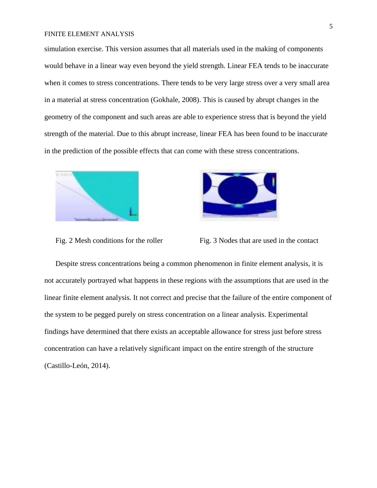
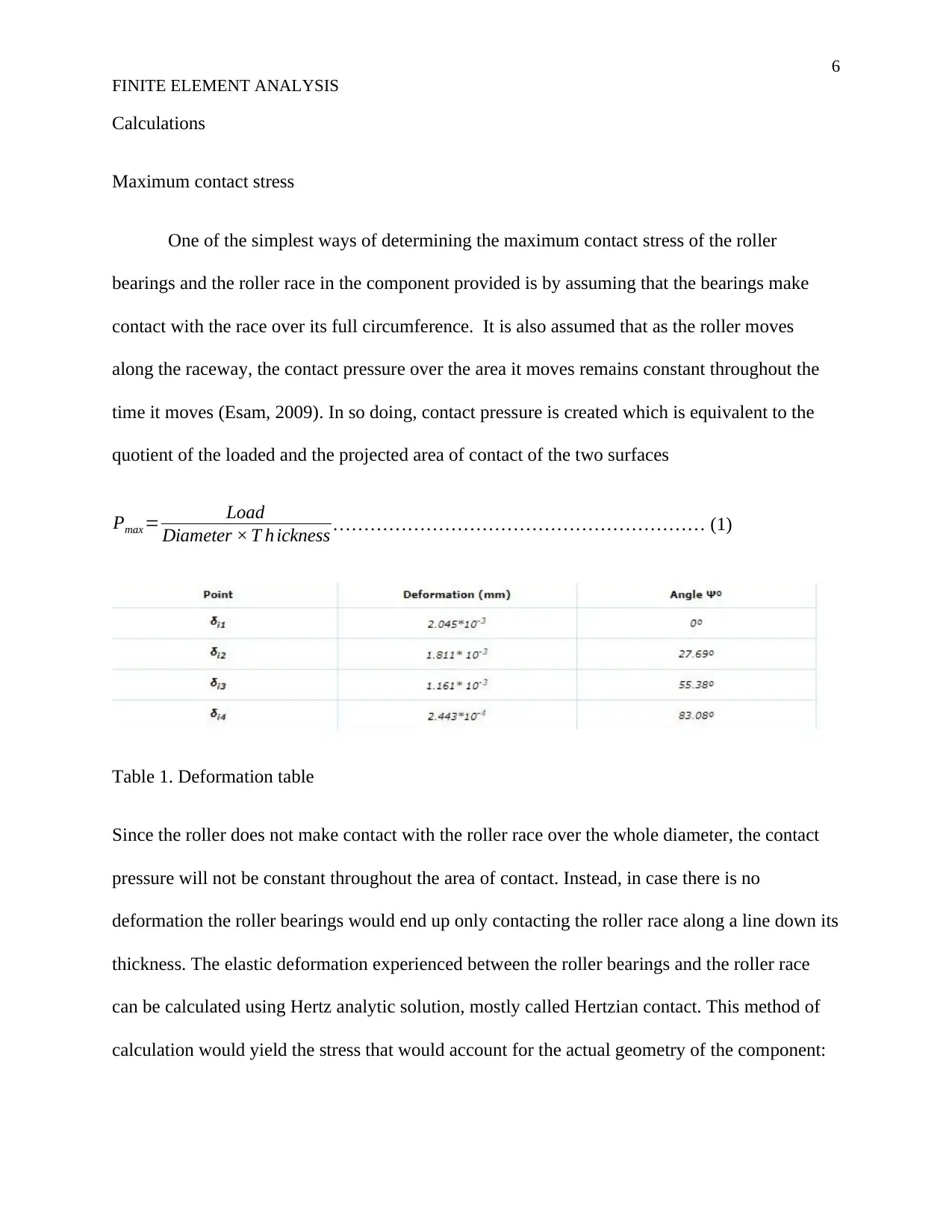
Fig. 2 Mesh conditions for the roller Fig. 3 Nodes that are used in the contact
Despite stress concentrations being a common phenomenon in finite element analysis, it is
not accurately portrayed what happens in these regions with the assumptions that are used in the
linear finite element analysis. It not correct and precise that the failure of the entire component of
the system to be pegged purely on stress concentration on a linear analysis. Experimental
findings have determined that there exists an acceptable allowance for stress just before stress
concentration can have a relatively significant impact on the entire strength of the structure
(Castillo-León, 2014).
FINITE ELEMENT ANALYSIS
simulation exercise. This version assumes that all materials used in the making of components
would behave in a linear way even beyond the yield strength. Linear FEA tends to be inaccurate
when it comes to stress concentrations. There tends to be very large stress over a very small area
in a material at stress concentration (Gokhale, 2008). This is caused by abrupt changes in the
geometry of the component and such areas are able to experience stress that is beyond the yield
strength of the material. Due to this abrupt increase, linear FEA has been found to be inaccurate
in the prediction of the possible effects that can come with these stress concentrations.
Fig. 2 Mesh conditions for the roller Fig. 3 Nodes that are used in the contact
Despite stress concentrations being a common phenomenon in finite element analysis, it is
not accurately portrayed what happens in these regions with the assumptions that are used in the
linear finite element analysis. It not correct and precise that the failure of the entire component of
the system to be pegged purely on stress concentration on a linear analysis. Experimental
findings have determined that there exists an acceptable allowance for stress just before stress
concentration can have a relatively significant impact on the entire strength of the structure
(Castillo-León, 2014).
6
FINITE ELEMENT ANALYSIS
Calculations
Maximum contact stress
One of the simplest ways of determining the maximum contact stress of the roller
bearings and the roller race in the component provided is by assuming that the bearings make
contact with the race over its full circumference. It is also assumed that as the roller moves
along the raceway, the contact pressure over the area it moves remains constant throughout the
time it moves (Esam, 2009). In so doing, contact pressure is created which is equivalent to the
quotient of the loaded and the projected area of contact of the two surfaces
Pmax = Load
Diameter × T h ickness …………………………………………………… (1)
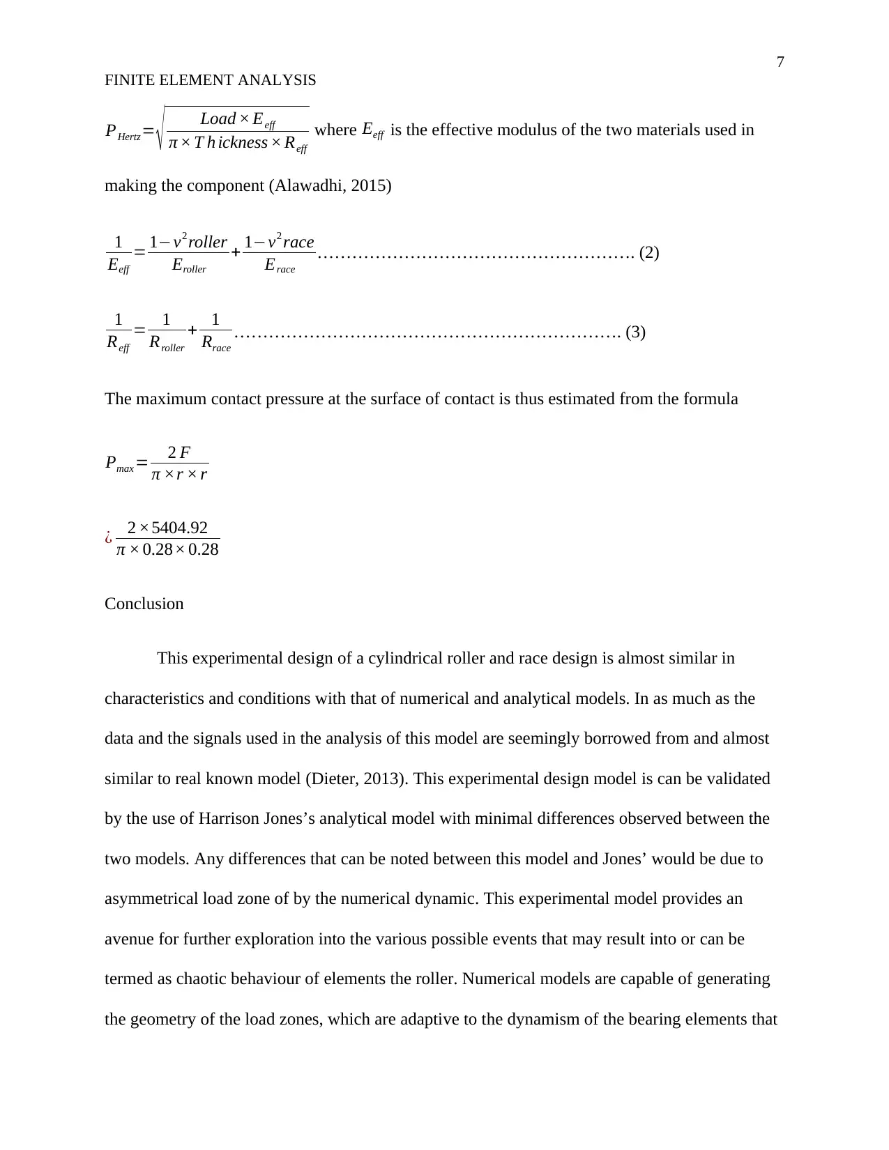
Table 1. Deformation table
Since the roller does not make contact with the roller race over the whole diameter, the contact
pressure will not be constant throughout the area of contact. Instead, in case there is no
deformation the roller bearings would end up only contacting the roller race along a line down its
thickness. The elastic deformation experienced between the roller bearings and the roller race
can be calculated using Hertz analytic solution, mostly called Hertzian contact. This method of
calculation would yield the stress that would account for the actual geometry of the component:
FINITE ELEMENT ANALYSIS
Calculations
Maximum contact stress
One of the simplest ways of determining the maximum contact stress of the roller
bearings and the roller race in the component provided is by assuming that the bearings make
contact with the race over its full circumference. It is also assumed that as the roller moves
along the raceway, the contact pressure over the area it moves remains constant throughout the
time it moves (Esam, 2009). In so doing, contact pressure is created which is equivalent to the
quotient of the loaded and the projected area of contact of the two surfaces
Pmax = Load
Diameter × T h ickness …………………………………………………… (1)
Table 1. Deformation table
Since the roller does not make contact with the roller race over the whole diameter, the contact
pressure will not be constant throughout the area of contact. Instead, in case there is no
deformation the roller bearings would end up only contacting the roller race along a line down its
thickness. The elastic deformation experienced between the roller bearings and the roller race
can be calculated using Hertz analytic solution, mostly called Hertzian contact. This method of
calculation would yield the stress that would account for the actual geometry of the component:
⊘ This is a preview!⊘
Do you want full access?
Subscribe today to unlock all pages.
Trusted by 1+ million students worldwide
7
FINITE ELEMENT ANALYSIS
PHertz= √ Load × Eeff
π × T h ickness × Reff
where Eeff is the effective modulus of the two materials used in
making the component (Alawadhi, 2015)
1
Eeff
= 1−v2 roller
Eroller
+ 1−v2 race
Erace
………………………………………………. (2)
1
Reff
= 1
Rroller
+ 1
Rrace
…………………………………………………………. (3)
The maximum contact pressure at the surface of contact is thus estimated from the formula
Pmax = 2 F
π ×r × r
¿ 2 ×5404.92
π × 0.28× 0.28
Conclusion
This experimental design of a cylindrical roller and race design is almost similar in
characteristics and conditions with that of numerical and analytical models. In as much as the
data and the signals used in the analysis of this model are seemingly borrowed from and almost
similar to real known model (Dieter, 2013). This experimental design model is can be validated
by the use of Harrison Jones’s analytical model with minimal differences observed between the
two models. Any differences that can be noted between this model and Jones’ would be due to
asymmetrical load zone of by the numerical dynamic. This experimental model provides an
avenue for further exploration into the various possible events that may result into or can be
termed as chaotic behaviour of elements the roller. Numerical models are capable of generating
the geometry of the load zones, which are adaptive to the dynamism of the bearing elements that
Paraphrase This Document
Need a fresh take? Get an instant paraphrase of this document with our AI Paraphraser

8
FINITE ELEMENT ANALYSIS
are in contact with the geometry. Such allows for prediction of the failure and location of critical
areas as well as the behaviour of the various components (Schell, 2014).
References
FINITE ELEMENT ANALYSIS
are in contact with the geometry. Such allows for prediction of the failure and location of critical
areas as well as the behaviour of the various components (Schell, 2014).
References
9
FINITE ELEMENT ANALYSIS
Alawadhi, E. M. (2015). Finite Element Simulations Using ANSYS, Second Edition. London:
CRC Press.
Castillo-León, J. (2014). Lab-on-a-Chip Devices and Micro-Total Analysis Systems: A Practical
Guide. Oxford: Springer.
Committee, A. I. (2010). ASM Handbook, Volume 22, Part 1. Chicago: ASM International.
Dieter, G. E. (2013). Handbook of Workability and Process Design. Oxford: ASM International.
Engineers, A. S. (2005). Proceedings of DETC, Volume 3, Parts 1-2. New York: American
Society of Mechanical Engineers.
Esam, A. (2009). Finite Element Simulations Using ANSYS. New York: CRC Press.
Gokhale, N. S. (2008). Practical Finite Element Analysis. Kansas: Finite To Infinite.
Kotzalas, M. N. (2006). Advanced Concepts of Bearing Technology,: Rolling Bearing Analysis,
Fifth Edition. New York: CRC Press.
Lee, H.-H. (2017). Finite Element Simulations with ANSYS Workbench 17. Sydney: SDC
Publications.
Schell, J. (2014). The Art of Game Design: A Book of Lenses, Second Edition. New York: CRC
Press.
Singh, R. (2006). Introduction to Basic Manufacturing Process and Workshop Technology.
Beijing: New Age International.
⊘ This is a preview!⊘
Do you want full access?
Subscribe today to unlock all pages.
Trusted by 1+ million students worldwide

10
FINITE ELEMENT ANALYSIS
Weisenberger, N. (2013). Coasters 101: An Engineer's Guide to Roller Coaster Design.
Macnhester: Nick Weisenberger.
FINITE ELEMENT ANALYSIS
Weisenberger, N. (2013). Coasters 101: An Engineer's Guide to Roller Coaster Design.
Macnhester: Nick Weisenberger.
1 out of 10
Your All-in-One AI-Powered Toolkit for Academic Success.
+13062052269
info@desklib.com
Available 24*7 on WhatsApp / Email
![[object Object]](/_next/static/media/star-bottom.7253800d.svg)
Unlock your academic potential
Copyright © 2020–2026 A2Z Services. All Rights Reserved. Developed and managed by ZUCOL.