Analysis of Rolls-Royce Aircraft Engines: Design and Performance
VerifiedAdded on 2021/06/17
|11
|2786
|86
Report
AI Summary
This report offers a comprehensive analysis of several Rolls-Royce aircraft engines, including the Avon, Dart, and Trent 800 series. The study begins with an introduction to engine functionality and energy conversion, followed by detailed examinations of specific engine models. The report delves into the design features, operational characteristics, and performance parameters of each engine, such as the Rolls-Royce Avon's axial flow turbojet, the Dart turbo-prop, and the Trent 800 turbofan. It explores design innovations, including the use of stacked engine arrangements and the evolution of materials like titanium and nickel alloys. The report also covers engine monitoring systems and their benefits, providing insights into how performance is measured and analyzed. Furthermore, the report discusses the materials used in key engine components like fans, compressors, turbines, and exhausts, emphasizing their impact on efficiency, durability, and noise reduction. The analysis provides valuable insights into the evolution and technological advancements in aircraft engine design and performance.

AIRCRAFT
By Name
Course
Instructor
Institution
Location
Date
By Name
Course
Instructor
Institution
Location
Date
Paraphrase This Document
Need a fresh take? Get an instant paraphrase of this document with our AI Paraphraser
Introduction
An engine is basically a device that is built to do an energy conversion from one from to
another. Most engines burn fuel which produces heat for doing work. In most machines, an
engine provides mechanical energy that brings a bout movement.
The engines used.
Rolls-Royce Avon mk300 series
The first axial flow jet engine that was successfully designed by the Rolls Royce was the
Rolls- Royce Avon. The turbojet type engine got a wide range of applications in the aircraft.
The maritime power, civilian and military they all sought the use and application of this
design. English Electric Lightning, a supersonic aircraft was used in the periods of cold war.
This craft had several unique design features including the twin engine arrangement, low-
mounted tail plane and a notched delta wing. During this period, there was an urgent need to
minimise frontal area, provide an engine airflow that is not interfered with across a wide
velocity range and arranging of two engines that could give enough thrust for the existing
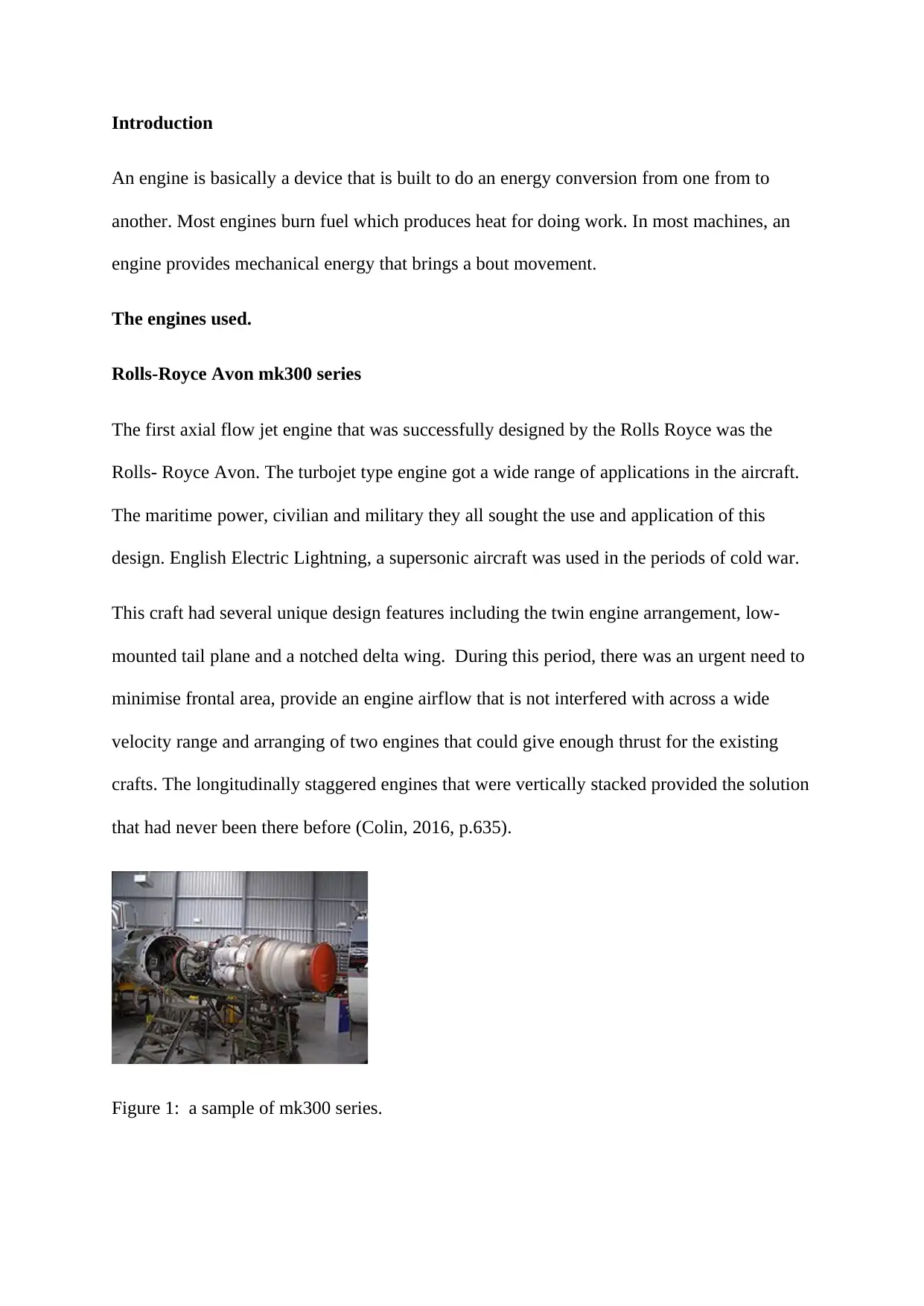
crafts. The longitudinally staggered engines that were vertically stacked provided the solution
that had never been there before (Colin, 2016, p.635).
Figure 1: a sample of mk300 series.
An engine is basically a device that is built to do an energy conversion from one from to
another. Most engines burn fuel which produces heat for doing work. In most machines, an
engine provides mechanical energy that brings a bout movement.
The engines used.
Rolls-Royce Avon mk300 series
The first axial flow jet engine that was successfully designed by the Rolls Royce was the
Rolls- Royce Avon. The turbojet type engine got a wide range of applications in the aircraft.
The maritime power, civilian and military they all sought the use and application of this
design. English Electric Lightning, a supersonic aircraft was used in the periods of cold war.
This craft had several unique design features including the twin engine arrangement, low-
mounted tail plane and a notched delta wing. During this period, there was an urgent need to
minimise frontal area, provide an engine airflow that is not interfered with across a wide
velocity range and arranging of two engines that could give enough thrust for the existing
crafts. The longitudinally staggered engines that were vertically stacked provided the solution
that had never been there before (Colin, 2016, p.635).
Figure 1: a sample of mk300 series.
This configuration allowed two thrust engines to be laid side by side or parallel but adjacent
to each other. The engines received air by a single nose inlet but the flow was vertically
directed to the cockpit with the nozzles tightly stacked. There was an excellent engine which
had no problems of asymmetrical thrust, very effective inlets and a low frontal area.
The disadvantage of this arrangement, however, was that any uncontrollable failure of one
engine could spread to the other engines. This lead to the higher cost of maintenance since
the maintenance process could call for replacement of the entire engines the initial design had
the ability to produce 50KN of thrust but with the introduction of the four -steps after burner,
the thrust was increased to 64. 2KN. This later improved with the full variable reheat
arrangement that allowed protection of aircraft structure from hot engine casing that could
otherwise be dangerous (Pam Lintott, 2011, p.275).
The stacked arrangement also complicated the maintenance work and leaking of fuel that
caused frequent fire hazards were just but reduced not eliminated. Very quick access to
certain parts of the engine was not easy. Down time maintenance increased. The main fuel
tank was contained on each side and was holding up to 1420 litres of fuel. The fuel
recuperator also had a capacity of 3200 litres. The recuperator therefore led to the increase in
the volume capacity of the engine. The major landing gear was put between the main tanks
and aft leading to the edge tanks. The gear legs reflected towards the wing tip and this
allowed thin main tyre to be filled with air to great pressure. When landing, the engine was
shut down to conserve break wearing process which was major drawback in this particular
design (Zou, 2018, p.356).
This kind of engine design allowed for the installation of a ventral weapon pack to load the
craft with different devices such as missiles and other war tools. The lightning employed
⊘ This is a preview!⊘
Do you want full access?
Subscribe today to unlock all pages.
Trusted by 1+ million students worldwide
liquid oxygen-based apparatus for the pilot, tapping of the engine compressors allowed for
the pressurisation and conditioning of the cockpit.
These design characteristics enabled it to be used as an interceptor fighter with the fastest
rate of climbing. The maximum climb height necessitated the use of the exhausts gases
during the take-off. Soon after normal take-offs, the nose level was reduced to achieve faster
acceleration of 430knots before starting a climb. Stabilisation would be realised at
450knots.The early lighting could move up to a speed of 1815km/h. Supersonic speed
threatened the effective entrance at the inlet central shock cone served as a compression
surface, thereby changing the direction of the airflow.
Design and performance of Rolls Royce dart turbo pro
The engine performance parameters are classified into different categories depending on the
parameter being targeted or under study indicated thermal efficiency. This is usually defined
as the ratio of the energy indicated on the engine to the input fuel. The mechanical efficiency
measures the break power relative to the indicated power (Lintot, 2012, p.222).
The mean effective pressure measures the no practical pressure which is usually multiplied
with the displacement to give the required work. The volumetric efficiency compares the air
fuel ratio which enters the cylinder and that which should enter in ideal conditions. The
relative efficiency gives the ratio of the normal thermal efficiency of the practical of actual
cycles to the ideal cycles (Colin, 2016, p.177). The power per unit area is usually taken as the
power per base area of the piston. And finally, specific fuel consumption which refers to the
mass of fuel consumed per power produced in kilowatts hour. Unit The brake thermal
efficiency gives the ratio produced power to the input fuel.
Paraphrase This Document
Need a fresh take? Get an instant paraphrase of this document with our AI Paraphraser
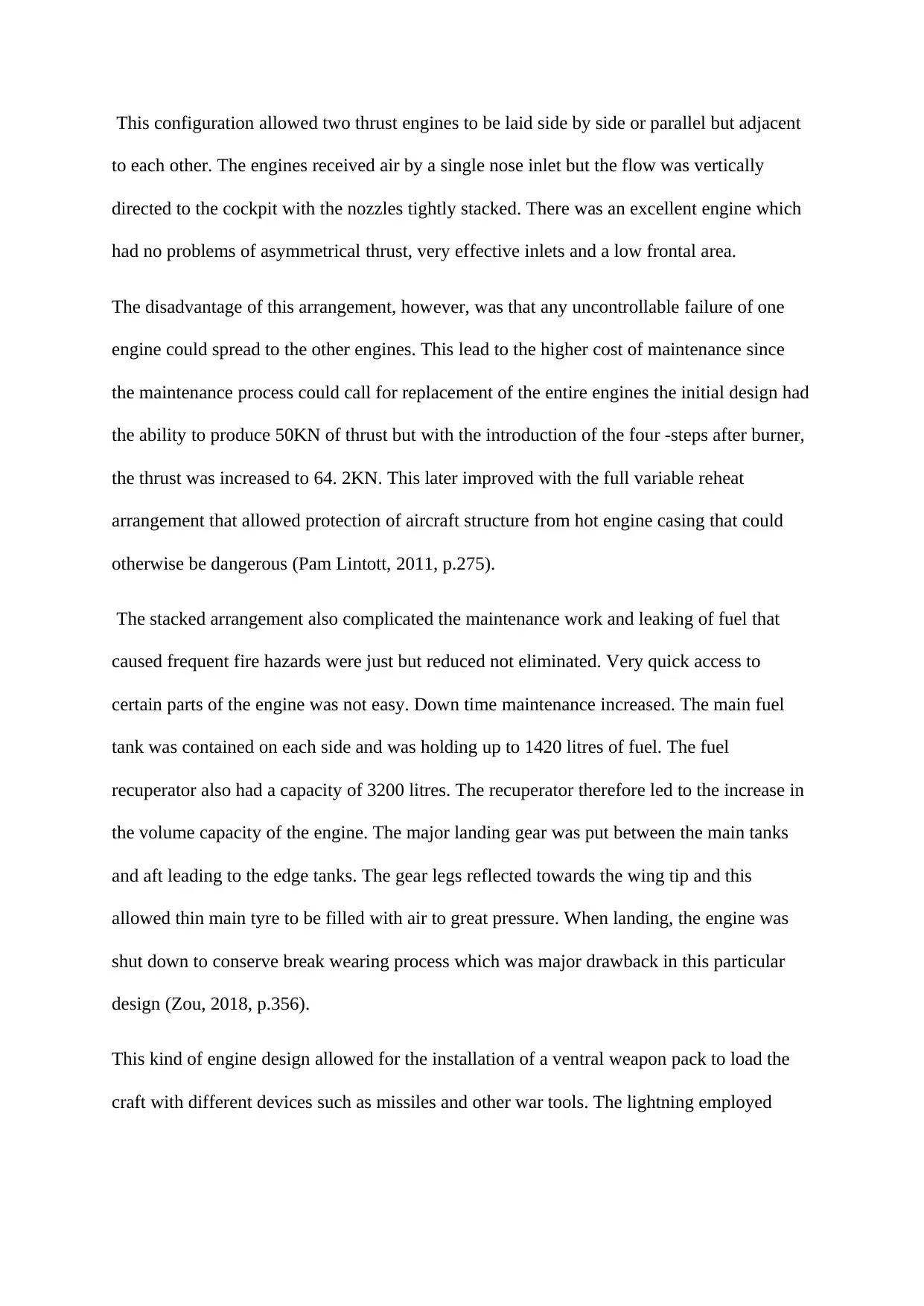
Figure 2; dart turbo engine sample.
The operation cycle of the turbo-prop is comparable to the jet engine. Air is drawn into the
engine through the pipe that is located on the front part. This air is compressed and later
allowed out of the compressor into the combustion chambers where fuel is burnt. The process
results into release of large amount of energy that forces columns of gas out of the chambers
past the turbines plates. This produces a roaring sound.
As the blades rotate, the driven compressor forces the air out of the engine. The noise
produced is just because the surfaces of the rotating parts are moving at a very high speed.
The performance of the pumps is better when the speed of the air leaving it is the same as that
coming from the craft. This explains why such engines are efficient at very high speed (El-
Sayed, 2017, p.172). The engine consisted of steps of circular compressors and turbine that
were coupled together to form a single shaft arrangement that could drive the reduction
gearbox. In order to save on weight, the reduction gearbox was redesigned with helical gear
teeth used instead of spur gears.
The magnesium was used other than aluminium for the casing parts, cooling parts and
impeller compressors. This arrangement helped in integral of oil tank. The hot oil assisted in
keeping the air intake from turning into ice under certain flight conditions.
The Vickers viscount demands were characterised by large horsepower targets. The reduction
leakage level together with a change in the internal structure improved greatly the flow of air
into the engine and thermal efficiency. The production darts had a shaft horse power of 1400
and this probably met the demands of the Vickers viscount. These engines were also
preferred because they were safe and very reliable.
Roll -Royce Trent 800
The Rolls-Royce Trent 800 refers to that high-bypass turbofan engine of the aircraft that was
specifically designed to be used on the Boeing777.In bid to expand their model 767, Boeing
launched. A thorough investigation on the possible areas of the required improvements is
done. The settled on a new larger aircraft design which was marked 777 and whose upward
push requirement was 360KN.Since the specifications available could not meet the
requirements, the Rolls proposed Trent800 (Turner, 2014, p.241).
In the year 2014, the design had incorporated technology from Trent1000 and Trent XWB
engines which includes semi-circular leading edges on the intermediate and pressure
compressor blades (Zou, 2018, p.188). The advantage of this engine is that it provides 0.7%
fuel-burn benefits. Some of the Boeing777 latest versions have thrust rating of between
334KNto 415KN.These are some of the lightest engines that are available. The maximum
thrust of the engine is 415.The thrust to weight ratio is usually taken as 5.6:1. The length the
engine is 4.37m, dry weight of 7484kg and a diameter of 2.79m, Eight-stage IP compressor
and six-stage HP compressor.
⊘ This is a preview!⊘
Do you want full access?
Subscribe today to unlock all pages.
Trusted by 1+ million students worldwide
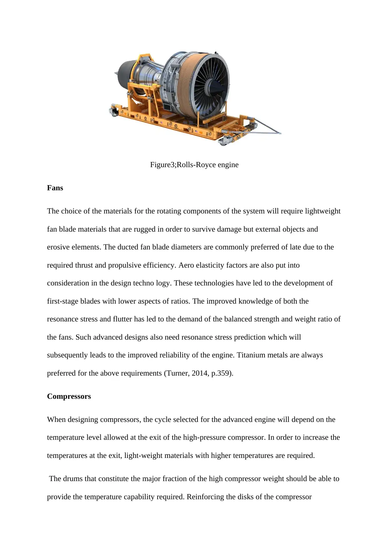
Figure3;Rolls-Royce engine
Fans
The choice of the materials for the rotating components of the system will require lightweight
fan blade materials that are rugged in order to survive damage but external objects and
erosive elements. The ducted fan blade diameters are commonly preferred of late due to the
required thrust and propulsive efficiency. Aero elasticity factors are also put into
consideration in the design techno logy. These technologies have led to the development of
first-stage blades with lower aspects of ratios. The improved knowledge of both the
resonance stress and flutter has led to the demand of the balanced strength and weight ratio of
the fans. Such advanced designs also need resonance stress prediction which will
subsequently leads to the improved reliability of the engine. Titanium metals are always
preferred for the above requirements (Turner, 2014, p.359).
Compressors
When designing compressors, the cycle selected for the advanced engine will depend on the
temperature level allowed at the exit of the high-pressure compressor. In order to increase the
temperatures at the exit, light-weight materials with higher temperatures are required.
The drums that constitute the major fraction of the high compressor weight should be able to
provide the temperature capability required. Reinforcing the disks of the compressor
Paraphrase This Document
Need a fresh take? Get an instant paraphrase of this document with our AI Paraphraser
improves its performance. Since the stress varies on the hoop direction, orienting fibres in
this direction produces a thin disc bore with a relatively faster response to the thermal
properties that leads to the reduction of thermal gradient and circumferential stresses. The
materials that are commonly used for the construction of compressor blades include nickel
alloys and titanium MMCs (Lintot, 2012, p.368).
Turbines
Turbines have greatly improved the temperature capability at the turbine inlets. Though the
temperatures cooling technology has greatly improved the allowable operating temperatures,
a lot is to be done still. The CMCs that are used in air foils, disks, and the engine cases must
enable the turbine to be operated at high temperatures without compromising on the
efficiencies of the engine itself. The material selected for this part therefore should be of high
corrosive resistance and of reduced ductility. They should have high compatibility with other
interfaces (El-Sayed, 2017, p.178).
Exhausts
The burnt gases of the engine must be sufficiently eliminated to improve on the efficiency of
the engine. To ensure that this particular objective is met, material selection is of
significance. The noise reduction from the exhaust gases must be taken into consideration.
Improved techniques of predicting load generation and subsequent structural response must
be adopted (Colin, 2016, p.261). Materials with high temperature gradients, high specific
damping and appropriate strength are recommendable. Not just for durability but also for
noise reduction.
Engine monitoring system
The engine monitoring system has data logging functions which allows the parameters to be
recorded. The loggings are done after every 6 seconds for a 100-hour depending on the
memory and arrangement of a particular system. The pilot will therefore periodically scan the
engine instruments and should there be any change in the prescribed parameters, an alarm
will be raised.
These data can be downloaded to the available computers and full analysis of the engine
displayed graphically. Trends of faults can then be followed. The benefits of fitting an engine
with engine monitoring system are numerous. The safety of the operator is highly taken care
of since the information is conveyed to the pilot (Zou, 2018, p.185). A review of the
operating parameters will help to identify if any problem is beginning to develop hence
corrective measures are taken immediately. The following steps maybe used to monitor the
performance of an engine.
Measurement of peak pressure using mechanical peak pressure gauges- This technique is
usually used in the four stroke engines where the peak pressure gauge is used to note the
pressure of the generated combustion cylinder. The gauge can be used to measure the
pressure even if the unit is not firing. This variation in the peak pressure is then taken for the
analysis (Colin, 2016, p.265). An indicator card measurement is used to check on the
performance of the engine by use of indicator drums and plotting the graph on the cards.
Another method is called Digital pressure indicator. This is an electronic garget that takes
the variation in the cylinder performance through power registration. There is use of
intelligent combustion monitoring that has the ability to check on the real time in the most
cylinder pressures. It has a very wide range of data processing for the evaluation of the
engine performance and malfunctions. The log book monitoring records the engine room
machinery that is always kept on the board mostly for the ships. In the original machines that
were used before, the aircrafts were simply equipped with a tachometer, oil pressure and oil
temperature gauge. The current designs have manifolds pressure gauge, exhaust gas gauges
and even pressure based fuel flow gauge.
⊘ This is a preview!⊘
Do you want full access?
Subscribe today to unlock all pages.
Trusted by 1+ million students worldwide

There is improved management of fuel mixture settings that subsequently saves fuel. In
certain aircrafts, the fuel saving will offset up to 500 hours of operation. The alarm function
of the engine lowers the high oil temperatures. The typical engine operating parameters are
the oil pressure, the voltage, outside air temperature, the RPM, the turbine inlet temperatures
gauges that are used on the turbocharged engines and particular cylinder head and exhaust
temperatures (Campbell, 2012, p.115).
The better engine operation is improved through reduced maintenance cost. When the
accurate data is obtained on the cause of fault and the fault is corrected in time, the cost of
maintenance will be reduced. The feedback can easily be communicated to the pilot who will
then respond by take appropriate measure.
Summary
The development of engines has undergone through different stages of development each
stage being characterised by a unique design that was an improvement on the previous one.
The increase demand of warplanes during the period of cold wars necessitated the rapid
development. Today the existing engines have high efficiency in power output and reduced
bulkiness. The size of these engines has reduced but power increased. Although certain
version of engines was faced off in the later date, their principles of operation are applicable
up to now.
References
Campbel, W.J., 2012. Speculators in Empire: Iroquoia and the 1768 Treaty of Fort Stanwi.
7th ed. New York: University of Oklahoma Press.
Campbell, W.J., 20124th. Speculators in Empire: Iroquoia and the 1768 Treaty of Fort
Stanwix. Liverpool: University of Oklahoma Press.
Paraphrase This Document
Need a fresh take? Get an instant paraphrase of this document with our AI Paraphraser
Colin, J., 2016. High Temperature Electronics Design for Aero Engine Controls and Health
Monitoring. 2nd ed. london: River Publishers.
El-Sayed, A.F., 2017. Aircraft Propulsion and Gas Turbine Engines,. 2nd ed. London: CRC
Press.
Lintot, P., 2012. Antique To Heirloom Jelly Roll Quilts: 12 Modern Quilt Patterns from
Vintage Patchwork Quilt Design. 6th ed. Moscow: "F+W Media, Inc.",.
Pam Lintott, 2011. More Layer Cake, Jelly Roll and Charm Quilts. 5th ed. New York: David
& Charles.
Turner, C., 2014. Designing and Building a Miniature Aero-Engine. 2nd ed. Manchester:
Crowood.
Zou, Z., 2018. Axial Turbine Aerodynamics for Aero-engines: Flow Analysis and
Aerodynamics . 5th ed. New York: Springer.
1 out of 11
Your All-in-One AI-Powered Toolkit for Academic Success.
+13062052269
info@desklib.com
Available 24*7 on WhatsApp / Email
![[object Object]](/_next/static/media/star-bottom.7253800d.svg)
Unlock your academic potential
Copyright © 2020–2026 A2Z Services. All Rights Reserved. Developed and managed by ZUCOL.