Analysis of Screw Pile Design Methods in Geotechnical Engineering
VerifiedAdded on 2023/06/11
|14
|2830
|357
Report
AI Summary
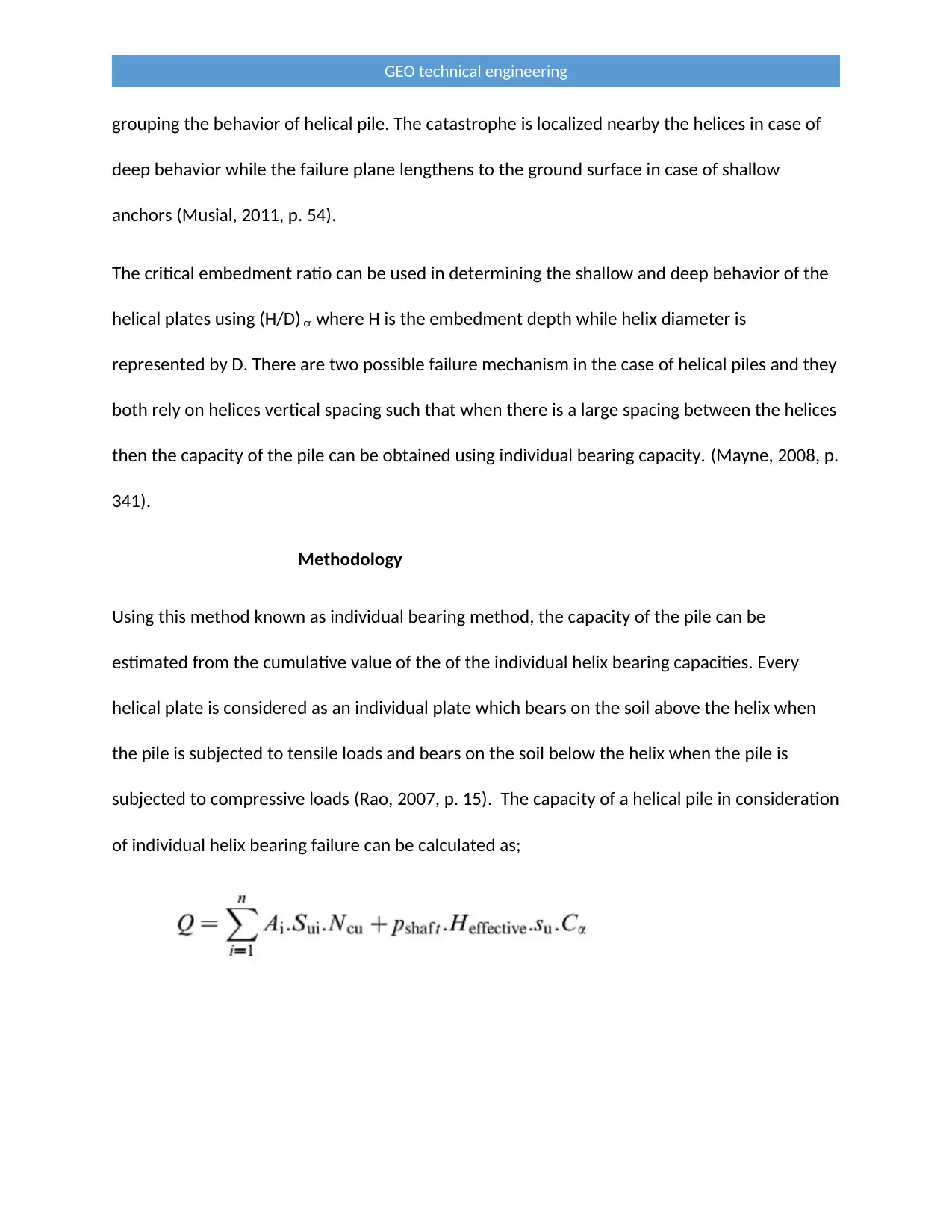
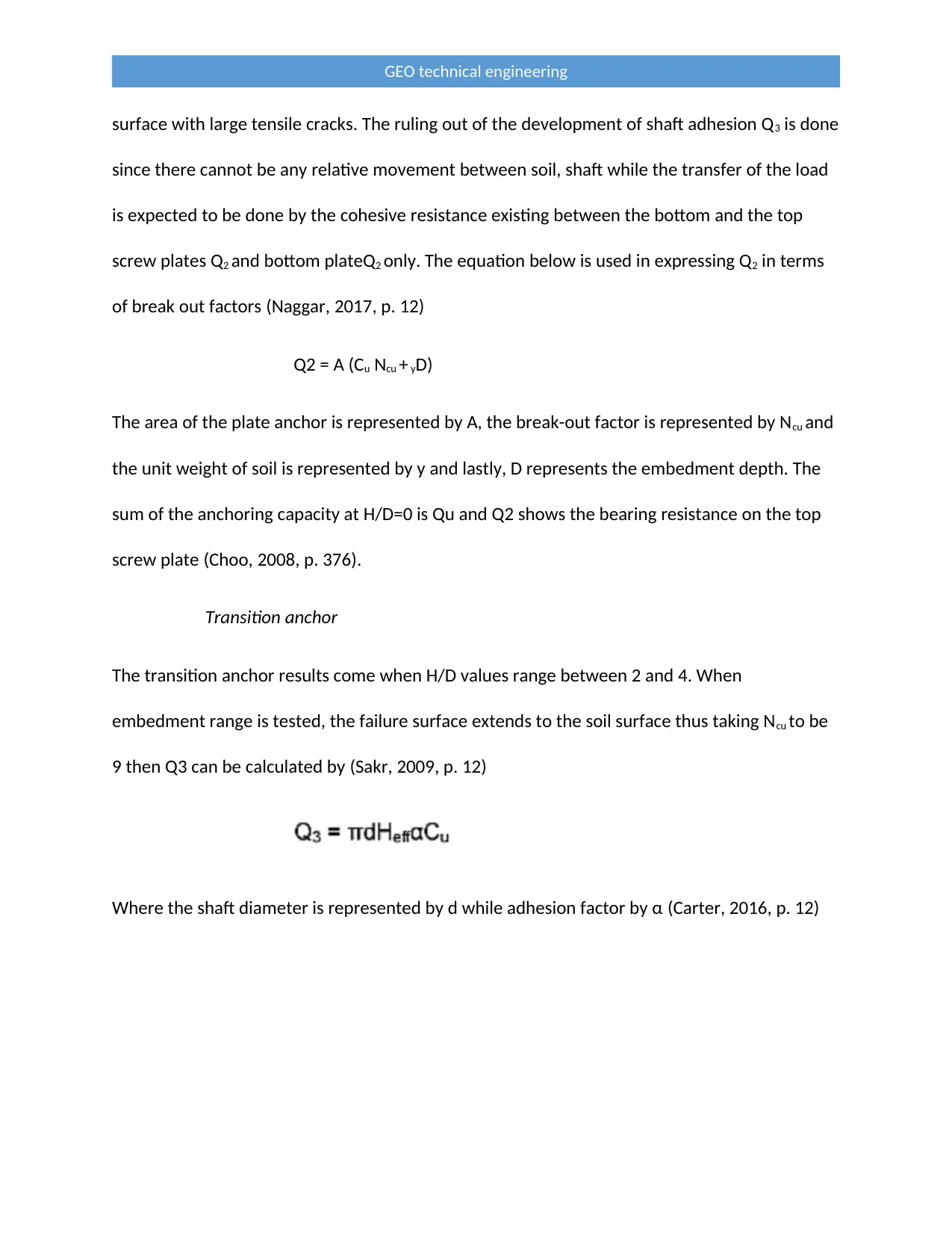
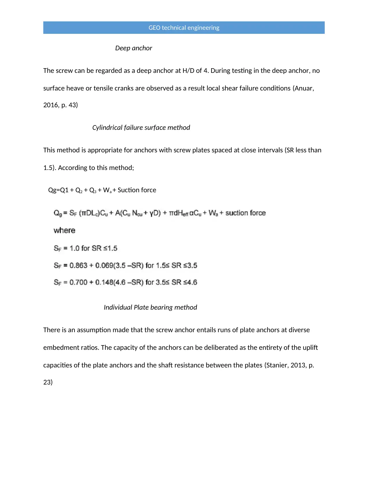
This report provides a comprehensive analysis of screw pile design methods in geotechnical engineering, focusing on axial capacity calculations using both individual bearing and cylindrical shear methods. It begins with background information on screw piles, highlighting their advantages such as environmental friendliness, ease of installation, and cost-effectiveness. The report then delves into a literature review, discussing various factors affecting screw pile performance, including soil conditions and installation techniques. Theoretical methods for calculating pile capacity are presented, considering soil strength, pile geometry, and embedment depth. The methodology section details the individual bearing method, where the capacity is estimated from the cumulative value of individual helix bearing capacities, and the cylindrical shear method, which approximates compressive capacity based on failure along a cylindrical shear surface. Experimental equipment and testing procedures are also described, including the use of model anchors, marine clay soil, and test tanks. The report concludes with a discussion of results, analyzing pullout load curves and categorizing anchors as shallow, transition, or deep based on their behavior under different conditions. This document is available on Desklib, a platform offering a wide range of study resources for students.

Name and Code of Unit:
Name of the Student
Name of the Professor
City/ State
Day/Month/Year
Introduction
GEO technical engineering
Name of the Student
Name of the Professor
City/ State
Day/Month/Year
Introduction
GEO technical engineering
Secure Best Marks with AI Grader
Need help grading? Try our AI Grader for instant feedback on your assignments.

In the first section of this proposal, background information on screw piles is discussed and also
the overview of the context of screw piles over stresses centered on the history and
insinuations of screw piles in regard to their merits and demerits. The proposal objectives are
also discussed followed by design essentials. Consequently, design methods are provided in this
proposal which is grouped axial capacity agenda via numerous methods, for example, individual
bearing method and cylindrical shear method. The project is concluded by comparing the two
different methods mentioned above.
Background information
Helical piles also known as screw piles are a steel screw- in pilling and ground anchoring system
which is applied in building foundations which are deep. The helical piles have been used
extensively in Western Canada to support superstructures mostly with applications in power
transmission towers, camps, and commercial buildings. The load structure is transmitted into
the pile by the shaft and the most commonly used material in the fabrication of helical piles is
steel and galvanized to repel corrosion. The invention of helical pile first took place by Irish
Engineer known as Alexander Mitchell and it was first used in the foundation system for river
moorings in 1830. Currently, the use of helical piles has adapted to the trends and engineers’
requirements (Phoon, 2008, p. 156).
The screw pile foundation is still used broadly and they usage has prolonged from lighthouses
to rail, roads, telecommunications and building work. The use of screw pile foundations is
necessary since they lessen the effect on the environment and it is cost efficiency (Prakash,
2006). Transportation of soil from the site is not a must since during screwing foundation there
GEO technical engineering

is less soil displacement. This method reduces the cost of transportation and reducing the
carbon footprint of the project.
The most important aspect of helical pile foundation include a reduction in carbon footprint,
risk reduction in the workforce, cost reduction, the project is accomplished in a shorter period,
accessibility and installation are very easy.
Summary of Helical piles and Anchors Advantages
Can be installed in any weather
Environmental friendly
Quick and easy to install
Immediate loading
Torque-to capacity correlation.
Aims
The objective of this proposal is to deliver better precision for entirely the project approaches
available on perpendicularly encumbered screw piles and to illustrate the contrasts and
methodology description for Individual and cylindrical bearing method.
Description and Scope
Literature Review
The screw pile according to Arup Geotechnics in the year 2005, were originally applied as
anchors and hence, were centered nearby tensile loads for example buried pipelines and
GEO technical engineering

transmission towers. The applications of screw pile have increased and currently, they are used
in structures subjected to lateral and compressive loading.
There are various conditions which are hindering the performance of the screw pile, for
example, the rocky soils, boulders, and bedrocks as discussed by Schmidt and Nasr in the year
2004. The axial capacity of the piles is reduced when some piles are trimmed for installation
assistance into gravel consisting of cobbles as discovered by the Sakr (2011). There are
dissimilar methods of design namely cylindrical shear method and individual bearing method
The downward pressure known as crowd and torque is applied during installation screw pile
but the crowd effect on the design process has not been found through the piles can arrive at
their required depth as a result of an increase in the crowd as claimed by Vito and Cook (2011).
A strong ground condition is needed before installation of screw pile since in a condition like
this the theoretical and actual base pressure is substantially less as asserted by Abramson and
Yttrium (2003).
The helical plate elevates bearing capacity can be expressed using a formula as a non-
dimensional function factors as mentioned by Maruipolshii & Trofimenkov (2005). In the case of
multi-helix anchors, the most methods which are used in calculating the pullout capacity are
the cylindrical shear method and individual bearing method (Musial, 2011, p. 34).
Theoretical methods of calculating pile capacity
The soil strength, geometry of the pile, overburden pressure and embedment depth influence
the axial capacity of the helical pile.The shallow and depth failure modes can be used in
GEO technical engineering
Secure Best Marks with AI Grader
Need help grading? Try our AI Grader for instant feedback on your assignments.

grouping the behavior of helical pile. The catastrophe is localized nearby the helices in case of
deep behavior while the failure plane lengthens to the ground surface in case of shallow
anchors (Musial, 2011, p. 54).
The critical embedment ratio can be used in determining the shallow and deep behavior of the
helical plates using (H/D) cr where H is the embedment depth while helix diameter is
represented by D. There are two possible failure mechanism in the case of helical piles and they
both rely on helices vertical spacing such that when there is a large spacing between the helices
then the capacity of the pile can be obtained using individual bearing capacity. (Mayne, 2008, p.
341).
Methodology
Using this method known as individual bearing method, the capacity of the pile can be
estimated from the cumulative value of the of the individual helix bearing capacities. Every
helical plate is considered as an individual plate which bears on the soil above the helix when
the pile is subjected to tensile loads and bears on the soil below the helix when the pile is
subjected to compressive loads (Rao, 2007, p. 15). The capacity of a helical pile in consideration
of individual helix bearing failure can be calculated as;
GEO technical engineering

When the spacing ratio is small, then the catastrophe tends to take place laterally the
cylindrical failure surface confined by the helices. To approximate the compressive capacity of
helical piles then the cylindrical shear model is recommended. In this particular method, the
occurrence of failure takes place along the surface of cylindrical shear with an equivalent
diameter to the average diameters of the helix (White, 2010, p. 456).
The pile capacity would be equal to the sum of the mobilized shear strength along the surface
of cylindrical shear, shaft resistance and soil bearing beneath the bottom helix for a pile in
compression as well as the bearing capacity of the soil above the uppermost helix in the case of
uplifting piles. From the cylindrical shear model, the calculation of axial capacity can be done
by;
GEO technical engineering

The torque correlation factor can be used in an approximation of helical piles where the
estimation of the capacity is done centered on correlation and installation torque factor (Henry,
2009).
Experimental
Equipment used in carrying out the experiment
The model anchors
Two sets of model anchors made with mild steel pipes welded using steel screw plates were
investigated. The set 1 anchors were a bit smaller compared to Set 2 anchors. The screw plates
had different diameters of 75mm and 33mm (Paulo, 2016, p. 6)
The soil used.
A marine clay soil from a coastal deposit was used in this experiment and this type of soil
consisting of silt and sand approximately 90% and 30% respectively. The plastic and liquid limit
for the soil were 32% and 82% respectively (Henry, 2009, p. 173).
The test Tanks
In this particular experiment, two types of test tanks were used; a cylindrical test tank of
300mm diameter and 600mm high was used in set 1 while in set 2 anchors rectangular test
tank 1200 x 1000 x 1200m was used. Elimination of boundary effect was necessary that is why
these sizes were used (Goswami, 2014, p. 54).
GEO technical engineering
Paraphrase This Document
Need a fresh take? Get an instant paraphrase of this document with our AI Paraphraser

Testing procedure
The test was performed in a soil bed prepared at a soft consistency of 0.28-0.60 which
appropriate during anchors installation in the field
Fig: Showing experimental setup
At the end of each test, the shear strength Cu of the soil bed which are undrained was measured
using field in-situ vane shear apparatus. Different depth locations were used in conducting the
test and the average value obtained was treated as Cu. The homogeneity and saturation were
also being tested for a few random samples that were taken out (Frikha, 2017, p. 110).
Testing programme
Anchors A1-A4 were tested in soil bed prepared at consistency indices of 0.28 and 0.45. The
influence of the consistency of soil on the model anchors having been elucidated anchors A5-A7
were tested at b1c =0.6 and with values of H/D between 0 and 8 (Fellenius, 2017, p. 78).
GEO technical engineering

Results and Discussions
Typical pullout load against upward movement curves of anchor A3 (SR =15, D=33mm and Ic of
o.45 as shown in the table below corresponding to H/D values of 0,1,2,3,4,6,8 and 10. Using
these values, it is noted that capacities increases with an increase in the H/D yet the H/D is zero
(Duncan, 2014). The gross ultimate uplift capacity Qg is contributed to by the cohesive
resistance along with cylinder. As a result of an increase in H/D from 0, there is an additional
contribution to Qg from bearing resistance on the top screw plate Q2 and the shaft adhesion above
the top plate. The value of anchor at Q g upward movement corresponding to H/D= 0 is about
15%-20% of screw diameter, at H/D=10 it is about 40%-50% (Das, 2007, p. 32).
The variation of net ultimate uplift capacity Qu with H/D shows all the test results for the set 1
anchor and in figure 10, the variation in soil consistency index of 0.28 is shown. An increase in
H/D from 0 to 2 will make an increase in Qu significant and in case of a further increase in H/D
then the rate of increase is considerably lower. The formation of well-developed cylindrical
failure planes having the same length (149mm) in anchors with SR less than 1.5 then will make
the capacities in respect to anchors A3 (SR=1.5) and A4 (SR=1.1) to be identical for all values of
all values of H/D ratio (Hicks, 2013, p. 6).
The anchors can be grouped as deep, shallow and transition based on the initial gradient,
transitional area and final gradient of the curve (Clemence, 2003, p. 561).
Shallow anchor
Up to H/D=2, there is a significant increase in Qu with H/D thus the screw anchor is considered
to be shallow. In the period of testing, the failure zones are found to be extending to the
GEO technical engineering

surface with large tensile cracks. The ruling out of the development of shaft adhesion Q3 is done
since there cannot be any relative movement between soil, shaft while the transfer of the load
is expected to be done by the cohesive resistance existing between the bottom and the top
screw plates Q2 and bottom plateQ2 only. The equation below is used in expressing Q2 in terms
of break out factors (Naggar, 2017, p. 12)
Q2 = A (Cu Ncu + yD)
The area of the plate anchor is represented by A, the break-out factor is represented by Ncu and
the unit weight of soil is represented by y and lastly, D represents the embedment depth. The
sum of the anchoring capacity at H/D=0 is Qu and Q2 shows the bearing resistance on the top
screw plate (Choo, 2008, p. 376).
Transition anchor
The transition anchor results come when H/D values range between 2 and 4. When
embedment range is tested, the failure surface extends to the soil surface thus taking Ncu to be
9 then Q3 can be calculated by (Sakr, 2009, p. 12)
Where the shaft diameter is represented by d while adhesion factor by α (Carter, 2016, p. 12)
GEO technical engineering
Secure Best Marks with AI Grader
Need help grading? Try our AI Grader for instant feedback on your assignments.

Deep anchor
The screw can be regarded as a deep anchor at H/D of 4. During testing in the deep anchor, no
surface heave or tensile cranks are observed as a result local shear failure conditions (Anuar,
2016, p. 43)
Cylindrical failure surface method
This method is appropriate for anchors with screw plates spaced at close intervals (SR less than
1.5). According to this method;
Qg=Q1 + Q2 + Q3 + Wa + Suction force
Individual Plate bearing method
There is an assumption made that the screw anchor entails runs of plate anchors at diverse
embedment ratios. The capacity of the anchors can be deliberated as the entirety of the uplift
capacities of the plate anchors and the shaft resistance between the plates (Stanier, 2013, p.
23)
GEO technical engineering

Conclusion
The paper has attempted to provide a succinct summary regarding helical anchors modeling
and also the installation effect of the helical plates on the soil penetrated which is the major
reason for the discrepancy between the measured and anticipated enactment of helical
anchors.
GEO technical engineering

Bibliography
Allen, E., 2011. Fundamentals of Building Construction Materials and Methods. s.l.:Grupo Planeta.
Anuar, H., 2016. Design and Construction of Soil Anchor. s.l.:Adventure Works Press.
Carter, M., 2016. Soil Properties and Their Correlations. s.l.:Readers Digest.
Choo, Y. S., 2008. Marine Operations Specialty Symposium. s.l.:Haufe Gruppe.
Clemence, S., 2003. Uplift Behavior of anchor foundations in soil. s.l.:Sanoma.
Das, B., 2007. Theoretical Foundations Engineering. s.l.:Informa.
Duncan, M., 2014. Soil Strength and Slope Stability. s.l.:Informa.
Frikha, W., 2017. Soil Testing, Soil Stability and Ground Improvement. s.l.:Wiley.
Henry, J., 2009. Significant Changes to the International Building Code. s.l.:Adventure Works Press.
Hicks, M., 2013. Installation Effects in Geotechnical Engineering. s.l.:McGraw-Hill Education.
Langer, J., 2007. Laterally Loaded Deep foundations. s.l.:Reed Elsevier.
Mayne, P., 2008. Geotechnical and Geophysical Site Characterization. s.l.:HarperCollins.
Musial, W., 2011. Large-Scale Offshore Wind Power in the United State. s.l.:Pearson.
Naggar, F. B. &. E., 2017. The Journal of Deep Foundations Institiute. Effects of Installation disturbance
on behavior of multi-helix piles in structured clays, 11(12), p. 13.
Paulo, U. o. S., 2016. Helical Anchors. Physical Modelling of the Behaviour of Helical Anchors, Issue 7, p.
20.
Phoon, K.-K., 2008. Reliability-Based Design in Geotechnical Engineering. s.l.:Media Participation .
Prakash, S., 2006. Pile Foundation in Engineering Practice. s.l.:Wolters Kluwer.
Rao, N., 2007. Indian Geotechnical Journal. Pullout Behavior of Screw and Sunction Anchors in Soft
Marine Clays, Volume 1, p. 37.
Ratay, R., 2012. Temporary Structures in Constructions. s.l.:Cambridge University press.
Sakr, M., 2009. Geotechnical Engineering. Performance of helical piles in oil sand, Volume 2, p. 17.
Stanier, J. B. &. S., 2013. Geotechnical Engineering. Modelling helical screw piles in soft clay and design
implications, 167(5), p. 14.
Tappenden, K., 2007. Predicting the Axial Capacity of Screw Piles in Western. s.l.:Random House.
GEO technical engineering
Paraphrase This Document
Need a fresh take? Get an instant paraphrase of this document with our AI Paraphraser

GEO technical engineering
1 out of 14
Related Documents

Your All-in-One AI-Powered Toolkit for Academic Success.
+13062052269
info@desklib.com
Available 24*7 on WhatsApp / Email
Unlock your academic potential
© 2024 | Zucol Services PVT LTD | All rights reserved.