A Research Paper on Screw Piles: Design, Applications, and Analysis
VerifiedAdded on 2020/05/08
|53
|16641
|80
Report
AI Summary
This research paper provides a comprehensive overview of screw piles, beginning with their introduction and historical context, including the invention by Alexander Mitchell. It delves into the description, applications, and uses of screw piles across various construction projects such as residential and commercial buildings, offshore wind turbines, and transmission towers. The paper explores the environmental sustainability of screw piles, including their ability to reduce noise pollution during installation and their potential for removal and reuse. It examines different types of screw piles, their configuration, and the parameters influencing their capacity, such as pile anchor length, installation torque, and geotechnical factors. Furthermore, the paper discusses the advantages of screw piles, including their ease of installation, resistance to earthquakes, and adaptability to various soil types, while also acknowledging their disadvantages. The conclusion summarizes the key findings and offers recommendations for future research and applications of screw piles within the field of civil engineering.

Screw Piles 1
RESEARCH PAPER ON SCREW PILES
A Research Paper on Screw Piles By
Student’s Name
Name of the Professor
Institutional Affiliation
City/State
Year/Month/Day
RESEARCH PAPER ON SCREW PILES
A Research Paper on Screw Piles By
Student’s Name
Name of the Professor
Institutional Affiliation
City/State
Year/Month/Day
Paraphrase This Document
Need a fresh take? Get an instant paraphrase of this document with our AI Paraphraser
Screw Piles 2
TABLE OF CONTENT
Item Page
INTRODUCTION……………………………………………………………….…….4
Description……….……………………………………………………….…...5
Invention ……………………………………………………………….……...6
Applications and Uses of Screw Piles………..……………………………….…….…7
Environmental sustainability……………………………………….……………….....10
Types of Screw Piles................................................................................................…...11
Configuration of Different Screw Piles..........................................................................12
Parameters Influencing the Capacity of Piles…………………………….…….……..17
Pile anchor length……………………………………………………………..17
Pile installation torque or minimum capacity………………………………...17
Geotechnical factors…………………………………………………………..18
The usage of Screw Piles in different types of soil……………………………………25
How Screw Pile Improve the Capacity of different Types of Soil……………………29
Potential advantages of using the crew piles and helical anchors……………………..37
Disadvantages of using the screw piles……………………………………………….41
Conclusion and Recommendation………………………………………….…………43
Bibliography………………………………………………………………..…………47
Screw Piles 3
INTRODUCTION
With the growing demand for the energy in the world of today, the companies of the energy are
looking for a cheap, reliable and new system of the foundation. Nowadays many wind turbines
of the offshore have been supported on the foundation of the monopile with the structures of the
jacket being the alternative. Because of the large sizes of foundation and the equipment of the
specialist needed to piles of large diameter gives the cheap and the solution of environmental
friendliness where the piles of high capacity can be installed without difficulty from smaller
vessels hence removing issues around window weathers ad transportation. The screw piles can
also be removed after they have reached the life of service, the can be removed from the site and
deployed through the action of the simple crew. Since they have a large resistance of pulling
capacity and vertical bearing, they might be the best solution for the structures that floats for
projects of as and deepwater oil. They are commonly used for the structure of onshore as the
towers for transmission and the pipeline anchor.
Many of the piles that are used in the offshore are driven open-ended and the steel tubes and their
sizes range from the conductors' standards, diameter of 0.76m to above diameter of 6m like the
ones in the turbines of the winds. Developments in the offshore renewable have produced more
concern about the effect of the noises of underwear on different species of fish and mammals of
marine species for the driving pile for the wind turbine. The noise that is being produced when
the pile is driven should be measured and it is known that the noise of underwater is up to a
distance of 70km. it is true that the noise is audible to the mammals of the marine over the entire
range.
Many methods have been invented to mitigate the produced noise by the driving of the pile such
as the screen of noise mitigation and curtain bubbles. Screw piles are the long shaft of tubular
⊘ This is a preview!⊘
Do you want full access?
Subscribe today to unlock all pages.
Trusted by 1+ million students worldwide
Screw Piles 4
diameter and small with single helix near many plates arranged at the interval on the shaft.
Helical plates enable the pile to be screwed to the placed by the application of the torque to the
shaft of the pile and this reduced the vibration and noise when fitting and reduces the
disturbances to the life of a marine. Screw piles have raised the capacity of the axial compression
when compared to the foundation of the conventional piles. The main benefit of using the screw
piles is the increase in the capacity of the uplift because of the effects of anchoring of the plates.
Also, they don’t release wastes soil, they don’t require the slurry of grout, can be used as the
piles of battered and are resistance to earthquakes and deformation.
Factors that influence the torque of installation of the pile are: the pressure of downward applied,
rate of soil advancement, level of the torque applied, installation depth, installation angle and the
type of the soil. Because of the action of push-pull, the mechanism failure covering the limit of
ultimate state response of the offshore turbines of the winds. Factors that affect the screw piles in
the uplift are geometrical properties of the screw piles, the ratio of the helix to the shaft, the
capacity of the structural type of the connection type of the helix plate. A significant aspect of
the geometry of the screw pile that has been subjected to investigations is the diameter of the
helical and the ratio between the diameter of the pile shaft and the diameter of the plate. The
torque for the installation increases with the increases in diameter of the plate, the thickness of
the plate, and plate numbers.
Screw piles are sometimes known as helical piles, screw anchor or helical anchor and are steel
crew in anchoring ground and piling systems used for constructing deep foundations. They are
valuable components in the belt of geotechnical too and can be improved to maintain many
dissimilar configurations with the more challenging condition of the subsurface. Their frequent
installation is easy and can lead to saving costs capacity and can be proved to the great point of
Paraphrase This Document
Need a fresh take? Get an instant paraphrase of this document with our AI Paraphraser
Screw Piles 5
certainty. The pile shaft structure’s load into the pile and screw pile plates are soldered to the
shaft pile in accordance with the condition of the ground intended. They can be designed to a
specific pitch or comprise of the flat plates welded at the identified pitches to the shaft of the
pile. Current use of the screw piles is foundations for residential and commercial building, light
standards, restoration of the failed foundations, retaining tieback walls, supports and bridge
abutments.
Description of Screw Piles
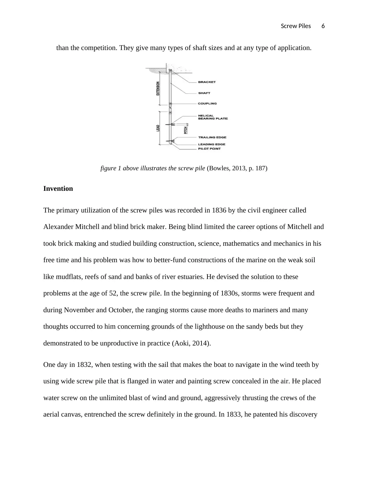
Screw piles are synthetic foundations of steel rotated to the ground to maintain the structures.
The constituents of screw piles comprise extension, lead, pile cap and plates of the helical
bearing. The first segment to the ground is the lead section, its pilot point is tapered and normally
have one or many plates of the helical bearing. The extension section advances the section of
lead deeper into the grounds till the required stratum of the bearing is attained. Extension section
may possess extra helical bearing plates but mostly are encompassed of the coupling and
dominant shaft (Abdelghany, 2012).
Screw piles have been used throughout the world in the projects and its uses such as foundations
for buildings, houses, bridges of the pedestrians, light poles and sound walls. Screw piles are also
used in the supporting essentials for the renovation of the unsuccessful foundations or to
supplement the present foundations for the support of the original load. They can be fitted at any
position or horizontally and compressive loads and tensile can be supported and are used for
retaining the systems of the walls, system of membrane roof, control of the pipeline buoyancy
and towers for transmission. The screw piles is a steel shaft with more or one helical plates
joined around (Ahmed, 2016). They are known as the deep foundation and are used to support
any type of load. The central shaft is contrived with grade tubing steel giving it high strength
certainty. The pile shaft structure’s load into the pile and screw pile plates are soldered to the
shaft pile in accordance with the condition of the ground intended. They can be designed to a
specific pitch or comprise of the flat plates welded at the identified pitches to the shaft of the
pile. Current use of the screw piles is foundations for residential and commercial building, light
standards, restoration of the failed foundations, retaining tieback walls, supports and bridge
abutments.
Description of Screw Piles
Screw piles are synthetic foundations of steel rotated to the ground to maintain the structures.
The constituents of screw piles comprise extension, lead, pile cap and plates of the helical
bearing. The first segment to the ground is the lead section, its pilot point is tapered and normally
have one or many plates of the helical bearing. The extension section advances the section of
lead deeper into the grounds till the required stratum of the bearing is attained. Extension section
may possess extra helical bearing plates but mostly are encompassed of the coupling and
dominant shaft (Abdelghany, 2012).
Screw piles have been used throughout the world in the projects and its uses such as foundations
for buildings, houses, bridges of the pedestrians, light poles and sound walls. Screw piles are also
used in the supporting essentials for the renovation of the unsuccessful foundations or to
supplement the present foundations for the support of the original load. They can be fitted at any
position or horizontally and compressive loads and tensile can be supported and are used for
retaining the systems of the walls, system of membrane roof, control of the pipeline buoyancy
and towers for transmission. The screw piles is a steel shaft with more or one helical plates
joined around (Ahmed, 2016). They are known as the deep foundation and are used to support
any type of load. The central shaft is contrived with grade tubing steel giving it high strength
Screw Piles 6
than the competition. They give many types of shaft sizes and at any type of application.
figure 1 above illustrates the screw pile (Bowles, 2013, p. 187)
Invention
The primary utilization of the screw piles was recorded in 1836 by the civil engineer called
Alexander Mitchell and blind brick maker. Being blind limited the career options of Mitchell and
took brick making and studied building construction, science, mathematics and mechanics in his
free time and his problem was how to better-fund constructions of the marine on the weak soil
like mudflats, reefs of sand and banks of river estuaries. He devised the solution to these
problems at the age of 52, the screw pile. In the beginning of 1830s, storms were frequent and
during November and October, the ranging storms cause more deaths to mariners and many
thoughts occurred to him concerning grounds of the lighthouse on the sandy beds but they
demonstrated to be unproductive in practice (Aoki, 2014).
One day in 1832, when testing with the sail that makes the boat to navigate in the wind teeth by
using wide screw pile that is flanged in water and painting screw concealed in the air. He placed
water screw on the unlimited blast of wind and ground, aggressively thrusting the crews of the
aerial canvas, entrenched the screw definitely in the ground. In 1833, he patented his discovery
⊘ This is a preview!⊘
Do you want full access?
Subscribe today to unlock all pages.
Trusted by 1+ million students worldwide
Screw Piles 7
in London and named the machine screw pile and its initial use was for ship anchorage. The pile
was rotated to the ground by animals and human power by the huge handled wood wheel called a
captain. In 1838, the utilization the helical piles for the groundwork of the lighthouse of Maplin
sands on the bank close to the river entry in the UK that was not stable (Aydin, 2012).
In 1858, Eugenius birch used the technology of screw pile of Mitchell to support the seaside
piers in England, every bridge pier had interconnected columns supported by the screw pile. The
piles sustained the weight of the carts, pedestrian, the ancillary structures and building. The
foundation had to support wind loads, tidal forces and frequent flows of ice. During the
expansion of the empire of the British, the helical piles were employed to sustain fresh bridges in
numerous continents and states (Bowles, 2013).
Between the 1850s and 1890s, more than one hundred lighthouses were built on the screw piles
foundations along the Gulf of Mexico and the coast of US. From 1900 to 1950, the use of the
screw piles reduced because there were many developments in the drilling equipment and
mechanical pile driving. Deep foundations like foundations of the Raymond drilled, Franki piles,
and belled piers were established. With the establishment of the current hydraulic torque, motors
improved the manufacturing and new methods of galvanization. Hydraulic torque was present in
the 1960s which enabled easy installation of the screw piles and they became the favoured
products for resisting tensile forces. Companies of electric utilities started using the screw pile
for tie-down piles on the towers for transmission on the utility pole for the guy wire (Budhu,
2014).
Paraphrase This Document
Need a fresh take? Get an instant paraphrase of this document with our AI Paraphraser
Screw Piles 8
Applications and Uses of Screw Piles
Screw piles have more current applications, in the market for the electrical effectiveness, screw
piles are utilized as the guy wire anchor and foundation for the transmission towers. A solitary
screw pile has the ability to sustain the tensile load usually on the order of 25 tons and anchors
and helical piles can minimize The screw piles can also be removed after they have reached the
life of service, the can be removed from the site and deployed through the action of the simple
crew. Since they have a large resistance of pulling capacity and vertical bearing, they might be
the best solution for the structures that floats for projects of as and deepwater oil. They are
commonly used for the structure of onshore as the towers for transmission and the pipeline
anchor e the quantity of the needed concrete and hence result in the saving cost more so in the
isolated places (Canadian Geotechnical Society, 2013).
In building a house, screw piles are used in the foundation's decks, additions, and shelters to
renovate the present foundation. They are installed for the addition of the single-story mountain
home. Controllable fitting apparatus and low cost of mobilization make the screw piles ideal for
places with small access to the backyard and narrow lots. These aspects joined with the
installation speed makes the screw piles cost-effective. They are used for the decks because of
the depth and pervasiveness of the frost and one of the features of screw piles its explosive soil
and resistance to the heave of the frost (Clemence, 2014).
There are many possibilities with the screw piles in the commercial building, the little effect of
the fitting apparatus and lightweight has made the screw piles substitute for the sensitive
wetlands area in the environment. Environment walks can be made by utilizing screw pile fitting
apparatus reinforced on the finalized walkway’s portion to prevent the apparatus from disturbing
Screw Piles 9
the delicate natural area. Some of the nature walks are fitted during the winter when the ground
is frozen to lessen the effect of the installation equipment (Das, 2011).
The capability of the screw piles to be fitted without a tremor in the low bedrooms areas within
the building has increased their uses inside the building where new loads are intended. Many
advantages of the screw piles like easy to install and speed made the construction of foundation
in the retail or the building of the warehouse be done in the off hours minus disturbance of the
administrator. The area of working may be partitioned off from the remaining building areas
with the visual or dust barrier and compressed, equipment of little noise can be used
(Geotechnics, 2013).
Screw piles are utilized in supporting the staircases and elevators to fulfil the requirements of the
new moneymaking structure for a variety of usage. They are also been utilized in supporting
dense equipment for developed within the commercial building. The slim screw piles have the
high ratio of dampening for the resistance of the vibrations of the machines. They can be
combined to form the group to carry large and heavy loads for the building construction and a
minimum of three piles are used to form group top carry the loads. Three piles can support the
load up to 600 tons and in this way, they have been used in many projects of high to low
constructions and can be installed in all weather conditions (Hanna, 2015).
Screw piles are also used in excavation shoring and underground structures. They are used in the
tie backs of many systems of shoring like soldier piling and sheet piling. Screw piles may also be
utilized as the nail soil by putting the screw plates of bearing alongside the shaft length. The
main function of screw pile is to transfer the load to the soil. Currently, they are used in many
applications in lateral loads, tension and compression. The pension applications of the screw
piles include guy anchor for the towers and poles, tiebacks for permanent and temporary
⊘ This is a preview!⊘
Do you want full access?
Subscribe today to unlock all pages.
Trusted by 1+ million students worldwide
Screw Piles 10
retaining walls and foundations tiebacks. They can be used in the foundations of the
underpinning sinking lifts, an element of deep foundation to support the boardwalks and
walkways, and braces of tilt-up walls. Also screw piles have become the choice of the foundation
for lateral application of load comprising stabilization of load, fences, towers, and poles (Zhang,
2010).
Environmental sustainability
Screw piles are practices of environmentally sustainable and conscientious. Their construction
needs less truck and uses less raw materials compared to other deep foundations types.
Replacement of the screw piles for other materials for deep foundations decreases the footprints
of carbon of the foundation and also reduces disturbances in the natural areas that are sensitive.
The arrangement of screw piles comprising a slender shaft and large bearing surface is a good
way to uses less raw materials. Their construction needs on order of sixty-five percent fewer raw
materials by heaviness to build than the steel screw piles and ninety-five percent fewer raw
materials by mass than the auger cast piles or drilled shafts (Zhang, 2013).
The foundation of the screw piles need few trips of the truck to and from the site of construction
and its installation need the shipping of the piles from the supplier to the place and utilization of
the machine for installation. Few truck tips mean less tear and wear of street, roads, and
highways, less pollution and less traffics. They reduce the overall footprints of carbon of the
projects, even though they are shipped for long distances to the construction site from the
supplier, the benefit is they need less raw materials by mass and fewer trips of the trucks that
reduce the intake of energy. They can also be installed with equipment with a low economy of
fuel and shorter duration than the other of deep foundations, saving fuel and reducing pollution
reduce carbon further (Vito, 2012).
Paraphrase This Document
Need a fresh take? Get an instant paraphrase of this document with our AI Paraphraser
Screw Piles 11
Screw piles can be used in low impact foundation projects that are sited in the sensitive areas like
historical sites, prairies, and wetlands, lightweight installation equipment reduced the
disturbances making few effects on the fragile ecosystems.
Types of Screw Piles
Shaft types of screw piles
There are four types of the screw piles available. They are explained briefly as followed
Square shaft: they are effective compared to pipe shafts with respects to the capacity gotten from
the installation energy. They will possess great axial capacity compared to the pipe shaft pile
fitted with the identical quantity of the energy of torsion into the similar soil profile. The shaft
piles are enhanced at the passing thick material compared to pipes shaft screw pipes. The cross-
sections of the square piles are slender hence, they don't have difficulty to resist fastening under
loads of compression without the soil support of surrounding. As long as there is good pressure
of the passive soil around the pile to avoid the bucking (Vickars, 2013)
Pipe shafts: these are not good in regard to the capacity of the load derived from the energy
installation but have greater sections magnitude when fastening of the square shaft or
unsubstantiated possible dimension is concerned. Their lead section doesn't penetrate dense
materials as the lead section for the square shaft.
Combo pile: a combo shafts or the combination shaft is the crew pile which possess the
advantage of the square and pipe shafts. Its section of lead is well at penetrating thick materials
and producing the capacities of the load. And is transmitted to the pipe shaft for extension of the
plain where the overload soils are soft and greater modulus sections are preferred for the
resistance of buckling or when the lateral resistance of the load is needed (Terzaghi, 2014).
Screw Piles 12
Helical pull-down micropile is a square shaft foundation with the plain section of extension
encased in the small diameter of the grout column. Pipe shafts can also be encased in less grout
column. Similar to combo, this type of screw pile also have the advantages of lead section of the
square shaft that penetrates dense materials. The added column of grout provides larger sections
modulus for the resistance of buckling and lateral resistance in the soft soil. And needs the case
of the steel. The grout in the soil develop the capacity of friction through the bond zone in a
good stratum of soil and greatly increases the total axial capacity of the pile and stiffness of the
load reaction of the pile. The pier of the grout also offers guard of the deterioration to the shaft of
steel (Tappenden, 2016).
Configuration of Different Screw Piles
There are least of one design constituent that must be put into consideration when selecting the
performance of the screw pile:
The mechanical capability of the specific screw plates: the automated strength or capacity of the
helical plate depends on the steel grade, thickness. Strength and diameter of the seal that joins it
to the pile. In most occasions, type automated capability is a distance of the helical plate
increases with the increase the shaft diameter. There should be more screw plates so the addition
of their specific capabilities may share the required pile load. The routine centred on the
requirement would need that the least quantity of the screw plates be given that is important in
sharing the load. The dimension of every plate should be left to the installation contractor as long
as the least number of given and other necessities are fulfilled like torque and least deepness
(Seider, 2015).
⊘ This is a preview!⊘
Do you want full access?
Subscribe today to unlock all pages.
Trusted by 1+ million students worldwide
1 out of 53

Your All-in-One AI-Powered Toolkit for Academic Success.
+13062052269
info@desklib.com
Available 24*7 on WhatsApp / Email
![[object Object]](/_next/static/media/star-bottom.7253800d.svg)
Unlock your academic potential
Copyright © 2020–2026 A2Z Services. All Rights Reserved. Developed and managed by ZUCOL.