Seabed Stability Analysis for Cross-Sea Bridge Pier Construction
VerifiedAdded on 2023/06/07
|19
|5796
|245
Report
AI Summary
This report explores the critical issue of seabed stability surrounding cross-sea bridge piers, focusing on the challenges posed by tidal and wave flows. It presents a physical study model of scour and countermeasures for sea-crossing bridge piers. The report details preliminary designs, including jack-up barges, temporary working platforms, and marine-based floating equipment, along with construction safety zones. It outlines the construction process, covering cofferdam and pile installation, concrete foundation construction, and scour protection placement. Pile drilling techniques and pier foundation design are also discussed, alongside hydrothermal and morphologic background. The report further delves into experimental setups and the analysis of scours around bridge dock assemblies, concluding with findings on ensuring the stability of seabed around cross-sea bridge piers. Desklib offers similar solved assignments for students.

Stability of Seabed around the Cross Sea ridge iers- B P 1
STABILITY OF SEABED AROUND THE CROSS SEA BRIDGE PIERS
A Research Paper on Bridge By
Student’s Name
Name of the Professor
Institutional Affiliation
City/State
Year/Month/Day
STABILITY OF SEABED AROUND THE CROSS SEA BRIDGE PIERS
A Research Paper on Bridge By
Student’s Name
Name of the Professor
Institutional Affiliation
City/State
Year/Month/Day
Paraphrase This Document
Need a fresh take? Get an instant paraphrase of this document with our AI Paraphraser
Stability of Seabed around the Cross Sea ridge iers- B P 2
Table of Contents
R D CINT O U TION...........................................................................................................................................3
R M AR D STHE P ELI IN Y E IGN..........................................................................................................................4
ack up bargeJ ...........................................................................................................................................5
emporary working platform supported on the temporary pilesT ..............................................................5
emporary working platform supported on the permanent pilesT .............................................................5
Marine based fl oating equipment- ...............................................................................................................6
emporary and permanent man made islandsT - .......................................................................................6
Construction safety zones and navigation protection....................................................................................6
C S R C R C SSON T U TION P O E ...........................................................................................................................6
Cofferdam installation..................................................................................................................................6
ile installationP ..........................................................................................................................................7
Concrete foundation construction...............................................................................................................8
he removal of cofferdamT .........................................................................................................................9
lacement of the scour protection around the perimeterP .........................................................................9
Suspension cable construction................................................................................................................10
ile drilling techniquesP ..........................................................................................................................11
ier and foundation designP ......................................................................................................................11
DR RMA A D M R C AC R DHY OTHE L N O PHOLOGI B KG OUN .............................................................................11
R M A SEXPE I ENT L ET UP..............................................................................................................................12
SC RS AR D R D D C ASS M S S A R DOU OUN THE B I GE O K E BLIE OF THE E B I GE...................................................14
C C SON LU ION.............................................................................................................................................17
RABIBLIOG PHY...........................................................................................................................................18
Stability of Seabed around the Cross Sea ridge iers- B P 3
INTRODUCTION
There are many problems in putting the sea overpass bridge piers in extra or less superficial
marine and coastal seawaters since as good as taking to endure the tidal and wave flows the piers
of the bridge have to be steady on the seabed that might be changing constantly. One of the main
problem experienced by the constructors is how to prevent, foresee scours of the seabed
sediments nearby the sea crossing bridge piers. This research paper present the physical study
model of the scour and the counter measurements of the scours for the sea crossing bridge piers.
Bridge is the combination of many distinct highlighted bridges and main bridges comprise the
continue tower of the ridge bridge. Scours is the normal occurrence initiated by the erosive act of
the water flowing on the banks and beds of sedimentary waterway.
There is scour that take place at the coastal places caused by the passage of the currents and
waves. Many recent scour related bridges catastrophes throughout the world have gotten
attention and more bridges failed due to the extreme scours around the piers. The
countermeasures of the local scours at the bridge piers can be divided into two groups namely;
flow altering and armoring devices. The armoring devices comprise the riprap, tetrapod, and
cable tied blocks. . Flow altering techniques can be used to protect the piers from the scours like
the deflectors, sacrificial piles and submerged vanes.
THE PRELIMINARY DESIGN
The design of the south-west anchor block consist of the 45by 44by 21 deep cap of concrete
supported by the grid of 1800mm concrete filled pile pipes. The bridge cap is hollow to
accommodate the spray chamber where the cable of the bridge strands are anchored to the cap
(Alton, 2012). The piles are battered at the slop of 4; 10 in the longitudinal direction of the
bridge. The piles are driven through the overburden materials down to the bedrock. Providing the
⊘ This is a preview!⊘
Do you want full access?
Subscribe today to unlock all pages.
Trusted by 1+ million students worldwide
Stability of Seabed around the Cross Sea ridge iers- B P 4
enough access to the foundation of marine is the primary consideration, considering the marine
foundation for the bridge is sizeable fairly and will need more working area for the construction
and the significant portion of the overall schedule for the construction of the bridge. Several
options for the providing the needed amount of the construction access are the self-elevating
platforms, temporary platforms of the working given support on the temporary piles, marine-
based methods using the floating equipment and the temporary man-made islands (Association,
2013).
Jack up barge
The jack barge comes equipped with the legs that can be lowered to the seabed and used to
lift the barge up above the sea level giving the large fixed platform for the working not affected
by the tides and swells. The barges can be fitted with large canes to support the anticipated
driving and the foundation of concrete anticipated for the bridge marine foundation. The
challenge of this site is the depth of weak structure above the bedrock. The bearing of the seabed
may not be sufficient to support the concentrated loads from the spuds when the large barges are
elevated making the barge spuds to sink in the mud. To resupply the work front and also to
accommodate the tidal windows, the supply barges would transit daily between onshore area of
staging and the site of work (Banks, 2015).
Temporary working platform supported on the temporary piles
The temporary piles supported the platform for the working gives the fixed structure upon
which the crane and the equipment can be put to install the foundation of the bridge. The
platform would be supported on many additional temporary piles and would extend around the
area of the foundation to give the adequate access for the foundation construction. The platform
allows the work of construction to process independent of the tides (Bridge, 2013).
Paraphrase This Document
Need a fresh take? Get an instant paraphrase of this document with our AI Paraphraser
Stability of Seabed around the Cross Sea ridge iers- B P 5
Temporary working platform supported on the permanent piles
The use of the permanent bridge foundation piles for the support of the platform gives
the advantage of not having to remove the piles after installing. The first few permanent piles are
fitted through the marine-based methods using the equipment that float on water. Once the
enough permanent piles are fitted the area of working can be erected and used to fit the balance
of the permanent piles and foundation work from the platform that is fixed. As the pile rows are
completed, the platform for working can be moved from one pile row to the next until all the
foundation piles are completed (Bridge, 2014).
Marine-based floating equipment
For the floating marine-based, method of construction, the material, cranes and equipment
are all brought to the front work on the floating deck barges. The marine derrick that is a flat
deck barge that has the duty cycle crawler crane mounted on it is normally needed (Centre,
2014).
Temporary and permanent man made islands
Because of the depth of the water at the proposed foundation of the bridge the construction
of the manmade island at every foundation site is considered to provide the uninterrupted process
of construction. The amount of materials removed and the required final elevation of the island
would depend on the intent of any offsetting measures like the creation or additional intertidal
habitats or even planting the additional grass beds or riparian vegetation (Cook, 2014)
Construction safety zones and navigation protection
Regardless of the selected method to gain the access for the bridge foundation construction.
There should be an impediment to the traffic of marine. The work faces occur in small areas in
open waters away from the channels and will be surrounded by the cofferdam (Dayaratnam,
2014)
Stability of Seabed around the Cross Sea ridge iers- B P 6
CONSTRUCTION PROCESS
Once the equipment access and a working area at the location of foundation have been
provided either through the use of a jack-up barge, platform and temporary work. The
construction of every marine foundation is presumed to follow a similar process generally. This
comprise the installation of the cofferdam. Installation of pile, work of concrete, and the pile cap
and anchor block, concrete construction, removal of the cofferdam, and the placement of the
scour protection (Dinar, 2016).
Cofferdam installation is required around every foundation of marine to allow dewatering
and excavating to the depth of the concrete pile cap soffit to facilitate work of concrete and
construction. It is anticipated the cofferdam would be fitted of steel sheet piles driven to the
depth in the sediments that are soft and extending up beyond the high level of water. The internal
bracing within the cofferdam would be used to support the sheet piles against the pressure from
outside. If the size of foundation and the poor soil at the site preclude the use of single sheet pile
cell. Utilizing a ring of the self-supporting shell cell piles may be an option. After the sheet pile
installation a steel template is installed inside the cofferdam to correctly position the piles. The
bottom of the foundation of the concrete will be situated to sit approximately at above the
existing mud line to avoid the need for the any overburden excavation from inside the cofferdam.
After the piles are installed (Duan, 2011). The template steel can be removed. Finally a concrete
seal is constructed through the tremie pouring, at the bottom of the excavation to allow for the
dewatering. After the cofferdam is dewatered the piles are cut off at the bottom of the anchor
block (Erskine, 2010).
⊘ This is a preview!⊘
Do you want full access?
Subscribe today to unlock all pages.
Trusted by 1+ million students worldwide
Stability of Seabed around the Cross Sea ridge iers- B P 7
Pile installation commences after the cofferdam is excavated and the steel pile template has
been installed. The proposed construction method for the pile installation involves the following
steps; set the pile into the sediments by the gravity
Vibrate the pile open-ended through the sediments until the tip is in the bedrock
When the pile reaches bedrock, seat the pile in the bedrock with the hammer impact
Extract the sediments in the pile with grab hammer or the airlift method
Drill the hole in the bedrock with the drill inside pile that act as the casing
For the rock doweled pile advance pile into under reamed hole and then the grout pile or
the rock socket pile. The pile should not be advanced but inserted the rebar cage and pour
tremie concrete into the hole of bottom.
Pile driving and the drilling comprise the clean out and socketing for the proposed diameter
of the pipe piles. The difference between the anchor pile and the trestle pile is that the anchor
piles are filled with the concrete after the rock socket is complete, the concrete pour will
continue the pile is filled to the top. Since the operation of pile driving are within the confines of
the cofferdam, the effects to the surrounding marine life is minimal. The pile will be of 65 long
and will need the welded splices of field. The splices of the field can be done on the barge with
the pile in the in situ of horizontal position depending on the crane size used (Geiger, 2017).
In the addition the rock socket, the anchors of the rock need to be installed for the tension
pile. The rock anchors consist of the strands tendon that are embedded in the bedrock and
anchored with the anchor block. After drilling for the rock socket a smaller diameter bit drill is
used in the bedrock to the needed depth. The inner casing and the strand anchor are lowered to
the bottom of the drilled shaft. Concreting for the rock socket is completed and the piles are
filled with the concrete. The rock anchor are finished by injecting the grout from the bottom of
the shaft upwards to the required depth to develop the anchor force (Gerwick, 2014). The strands
are stressed from within the block and the remaining length of the shaft is grouted to protect the
anchors from corrosion (Gerwick, 2013).
Paraphrase This Document
Need a fresh take? Get an instant paraphrase of this document with our AI Paraphraser
Stability of Seabed around the Cross Sea ridge iers- B P 8
Concrete foundation construction would progress same to the onshore construction
after the completion of the pipe fitting. The connection between the pile caps and the piles
consists of a reinforced concrete plug inside every pile head with the reinforcement cage
extending up into the mass concrete of the icecap. The building of the pile caps and other
elements of the concrete in the series of the lifts separated by the joints of construction. Supply
of large volume of concrete needed for the foundation will need to be done through the barge.
Concrete placement will be affected by the restriction of tides and may impose longer times of
construction (Hamed, 2016).
Considering the concrete volume needed at the foundation of bridge. There are two methods
of supplying the concrete to the work face. One involve the concrete produced by the onshore
batch plant and delivered to the work face through concrete trucks on the barge and the other one
involve using the actual floating batch plant satiated adjacent to the work site. The floating batch
is efficient to supply the concrete hence mere susceptible to the tidal and weather related to the
down times (Hardyman, 2016).
The removal of cofferdam can start once the required foundation concreting work are
above the high level of water. The material excavated can be placed within the cofferdam
allowing the removal of internal bracing layer by layer. The steel sheet piles can be removed
with the vibratory hammer. Consideration for the leaving the sheet piles in place below the top of
the footing to help with the protection of the scour.
Placement of the scour protection around the perimeter if the anchor block
would be conducted soon after removal of the cofferdam. Due to the shallow alter around the
anchor block, the protection would be placed through the marine-based methods using the tidal
Stability of Seabed around the Cross Sea ridge iers- B P 9
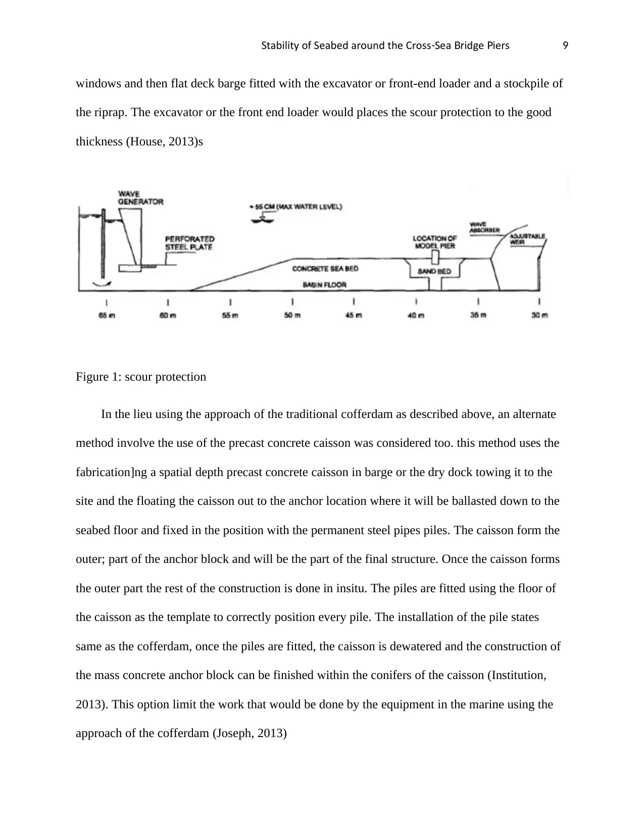
windows and then flat deck barge fitted with the excavator or front-end loader and a stockpile of
the riprap. The excavator or the front end loader would places the scour protection to the good
thickness (House, 2013)s
Figure 1: scour protection
In the lieu using the approach of the traditional cofferdam as described above, an alternate
method involve the use of the precast concrete caisson was considered too. this method uses the
fabrication]ng a spatial depth precast concrete caisson in barge or the dry dock towing it to the
site and the floating the caisson out to the anchor location where it will be ballasted down to the
seabed floor and fixed in the position with the permanent steel pipes piles. The caisson form the
outer; part of the anchor block and will be the part of the final structure. Once the caisson forms
the outer part the rest of the construction is done in insitu. The piles are fitted using the floor of
the caisson as the template to correctly position every pile. The installation of the pile states
same as the cofferdam, once the piles are fitted, the caisson is dewatered and the construction of
the mass concrete anchor block can be finished within the conifers of the caisson (Institution,
2013). This option limit the work that would be done by the equipment in the marine using the
approach of the cofferdam (Joseph, 2013)
⊘ This is a preview!⊘
Do you want full access?
Subscribe today to unlock all pages.
Trusted by 1+ million students worldwide
Stability of Seabed around the Cross Sea ridge iers- B P 10
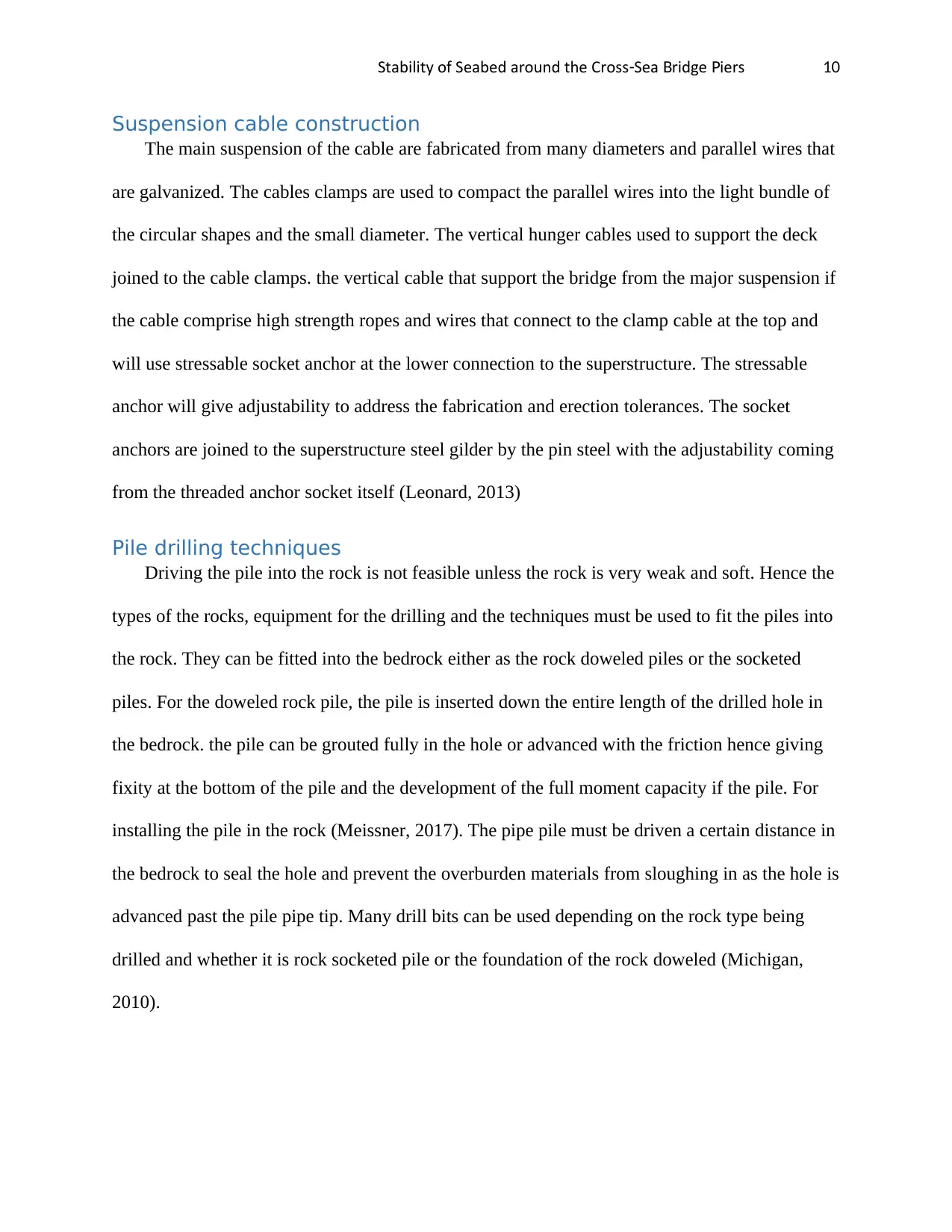
Suspension cable construction
The main suspension of the cable are fabricated from many diameters and parallel wires that
are galvanized. The cables clamps are used to compact the parallel wires into the light bundle of
the circular shapes and the small diameter. The vertical hunger cables used to support the deck
joined to the cable clamps. the vertical cable that support the bridge from the major suspension if
the cable comprise high strength ropes and wires that connect to the clamp cable at the top and
will use stressable socket anchor at the lower connection to the superstructure. The stressable
anchor will give adjustability to address the fabrication and erection tolerances. The socket
anchors are joined to the superstructure steel gilder by the pin steel with the adjustability coming
from the threaded anchor socket itself (Leonard, 2013)
Pile drilling techniques
Driving the pile into the rock is not feasible unless the rock is very weak and soft. Hence the
types of the rocks, equipment for the drilling and the techniques must be used to fit the piles into
the rock. They can be fitted into the bedrock either as the rock doweled piles or the socketed
piles. For the doweled rock pile, the pile is inserted down the entire length of the drilled hole in
the bedrock. the pile can be grouted fully in the hole or advanced with the friction hence giving
fixity at the bottom of the pile and the development of the full moment capacity if the pile. For
installing the pile in the rock (Meissner, 2017). The pipe pile must be driven a certain distance in
the bedrock to seal the hole and prevent the overburden materials from sloughing in as the hole is
advanced past the pile pipe tip. Many drill bits can be used depending on the rock type being
drilled and whether it is rock socketed pile or the foundation of the rock doweled (Michigan,
2010).
Paraphrase This Document
Need a fresh take? Get an instant paraphrase of this document with our AI Paraphraser
Stability of Seabed around the Cross Sea ridge iers- B P 11
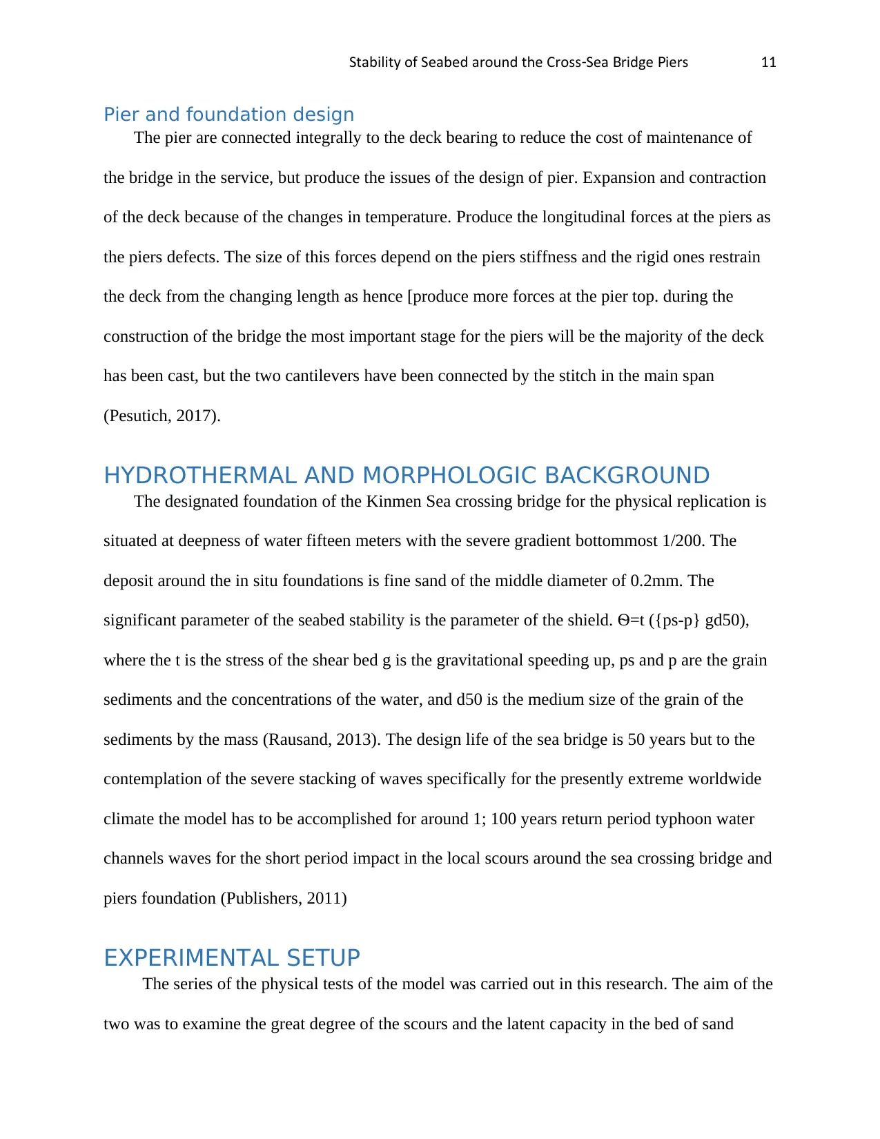
Pier and foundation design
The pier are connected integrally to the deck bearing to reduce the cost of maintenance of
the bridge in the service, but produce the issues of the design of pier. Expansion and contraction
of the deck because of the changes in temperature. Produce the longitudinal forces at the piers as
the piers defects. The size of this forces depend on the piers stiffness and the rigid ones restrain
the deck from the changing length as hence [produce more forces at the pier top. during the
construction of the bridge the most important stage for the piers will be the majority of the deck
has been cast, but the two cantilevers have been connected by the stitch in the main span
(Pesutich, 2017).
HYDROTHERMAL AND MORPHOLOGIC BACKGROUND
The designated foundation of the Kinmen Sea crossing bridge for the physical replication is
situated at deepness of water fifteen meters with the severe gradient bottommost 1/200. The
deposit around the in situ foundations is fine sand of the middle diameter of 0.2mm. The
significant parameter of the seabed stability is the parameter of the shield. Ѳ=t ({ps-p} gd50),
where the t is the stress of the shear bed g is the gravitational speeding up, ps and p are the grain
sediments and the concentrations of the water, and d50 is the medium size of the grain of the
sediments by the mass (Rausand, 2013). The design life of the sea bridge is 50 years but to the
contemplation of the severe stacking of waves specifically for the presently extreme worldwide
climate the model has to be accomplished for around 1; 100 years return period typhoon water
channels waves for the short period impact in the local scours around the sea crossing bridge and
piers foundation (Publishers, 2011)
EXPERIMENTAL SETUP
The series of the physical tests of the model was carried out in this research. The aim of the
two was to examine the great degree of the scours and the latent capacity in the bed of sand
Stability of Seabed around the Cross Sea ridge iers- B P 12
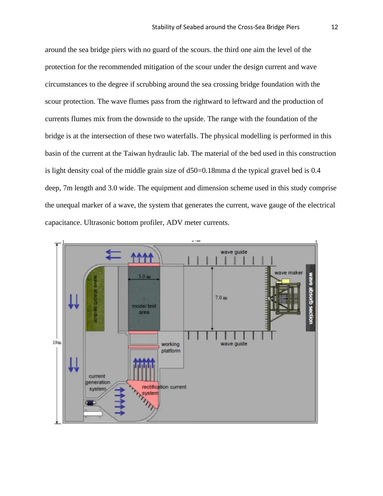
around the sea bridge piers with no guard of the scours. the third one aim the level of the
protection for the recommended mitigation of the scour under the design current and wave
circumstances to the degree if scrubbing around the sea crossing bridge foundation with the
scour protection. The wave flumes pass from the rightward to leftward and the production of
currents flumes mix from the downside to the upside. The range with the foundation of the
bridge is at the intersection of these two waterfalls. The physical modelling is performed in this
basin of the current at the Taiwan hydraulic lab. The material of the bed used in this construction
is light density coal of the middle grain size of d50=0.18mma d the typical gravel bed is 0.4
deep, 7m length and 3.0 wide. The equipment and dimension scheme used in this study comprise
the unequal marker of a wave, the system that generates the current, wave gauge of the electrical
capacitance. Ultrasonic bottom profiler, ADV meter currents.
⊘ This is a preview!⊘
Do you want full access?
Subscribe today to unlock all pages.
Trusted by 1+ million students worldwide
1 out of 19
Your All-in-One AI-Powered Toolkit for Academic Success.
+13062052269
info@desklib.com
Available 24*7 on WhatsApp / Email
![[object Object]](/_next/static/media/star-bottom.7253800d.svg)
Unlock your academic potential
Copyright © 2020–2026 A2Z Services. All Rights Reserved. Developed and managed by ZUCOL.