Electronics IAP: Self-Balancing Robot Design and Implementation
VerifiedAdded on 2022/11/14
|53
|15165
|281
Project
AI Summary
This project focuses on the design and implementation of a self-balancing robot capable of following a line. The robot utilizes an IMU sensor (MPU6050) to measure tilt angles, employing a complementary filter to correct sensor errors from the gyroscope and accelerometer. A PID controller is implemented to maintain the robot's balance by controlling motor movements based on the tilt angle. The design includes the hardware components like the chassis, motors, and the IMU sensor, along with the software algorithms for sensor data processing and motor control. The methodology involves literature review, hardware selection, software development, and implementation of control systems, including a block diagram and risk assessment. The project aims to create a stable, autonomous robot that can balance itself and follow a predefined line, with potential future improvements such as obstacle avoidance and enhanced controller designs.
Electronics
IAP – Thesis
Line Following Self – Balancing Robot
Student Name –
Student ID –
1
IAP – Thesis
Line Following Self – Balancing Robot
Student Name –
Student ID –
1
Paraphrase This Document
Need a fresh take? Get an instant paraphrase of this document with our AI Paraphraser
Contents
Abstract.................................................................................................................................................3
1.Introduction........................................................................................................................................3
1.1 Introduction.................................................................................................................................3
1.2 Motivation...................................................................................................................................3
1.3 Aim and Objectives......................................................................................................................4
1.4 Methodology...............................................................................................................................4
2. Literature Review..............................................................................................................................7
2.1 Introduction.................................................................................................................................7
2.2 Inverted Pendulum......................................................................................................................8
3. Hardware.........................................................................................................................................17
3.1 Complementary filter.................................................................................................................21
3.2 Gyroscope..................................................................................................................................22
3.3 Accelerometer:..........................................................................................................................22
3.4 Software:...................................................................................................................................22
4. Implementation...............................................................................................................................23
4.1 Gantt chart:................................................................................................................................23
4.2 Risk:...........................................................................................................................................24
4.3 Block Diagram:...........................................................................................................................25
5. Designing.........................................................................................................................................27
5.1 Control System :........................................................................................................................27
5.2 PID Controller............................................................................................................................28
5.3 Design of Complementary filter.................................................................................................32
5.4 Design of PID Controller.............................................................................................................33
6. Results.............................................................................................................................................36
6.1 Conclusion.................................................................................................................................36
6.2 Future Work :.............................................................................................................................36
References...........................................................................................................................................37
2
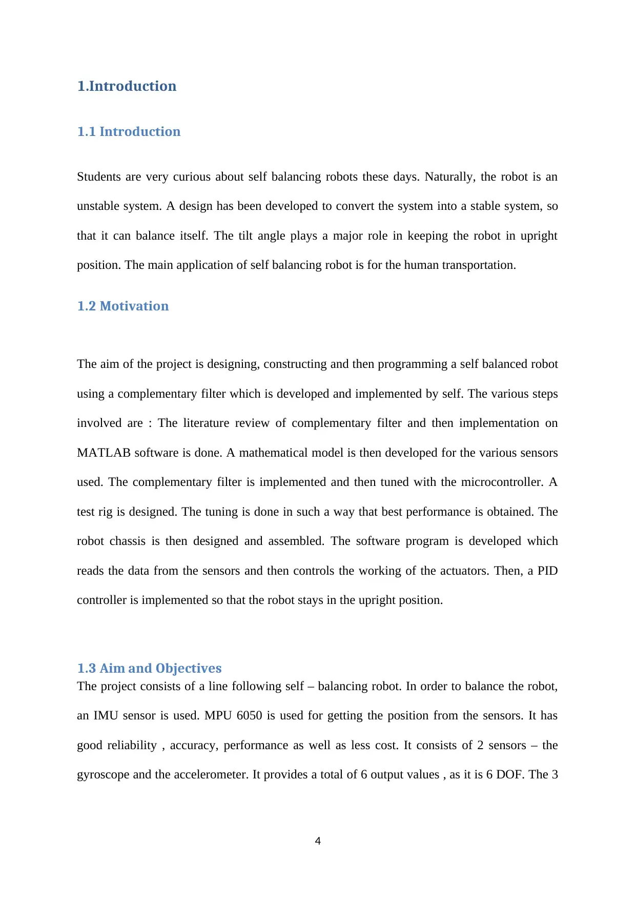
Abstract
The project consists of design of a self – balancing robot. A 2 wheel robot can be compared
to an inverted pendulum. It is normally an unstable system which needs to be stabilised. The
tilt angle needs to be measured continuously and then maintained at a stabilised reference
value. For the measurement of the angle value, the sensors used are gyroscope and the
accelerometer. The readings provided by them consist of various errors due to bias and
temperature. These values need to be corrected by the help of a filter. In this project, a
complementary filter has been used. The controller used to control to output in a stable limit,
a PID controller has been used. This provides a value of tilt angle. This value is processed
using a microcontroller. The value of tilt angle has to be maintained at a reference value. The
motors are driven accordingly so as to provide forward or backward movement to the robot
for maintain the required upright position. This helps to design a self – balancing robot. The
robot can balance itself on its own using this system.
3
⊘ This is a preview!⊘
Do you want full access?
Subscribe today to unlock all pages.
Trusted by 1+ million students worldwide
1.Introduction
1.1 Introduction
Students are very curious about self balancing robots these days. Naturally, the robot is an
unstable system. A design has been developed to convert the system into a stable system, so
that it can balance itself. The tilt angle plays a major role in keeping the robot in upright
position. The main application of self balancing robot is for the human transportation.
1.2 Motivation
The aim of the project is designing, constructing and then programming a self balanced robot
using a complementary filter which is developed and implemented by self. The various steps
involved are : The literature review of complementary filter and then implementation on
MATLAB software is done. A mathematical model is then developed for the various sensors
used. The complementary filter is implemented and then tuned with the microcontroller. A
test rig is designed. The tuning is done in such a way that best performance is obtained. The
robot chassis is then designed and assembled. The software program is developed which
reads the data from the sensors and then controls the working of the actuators. Then, a PID
controller is implemented so that the robot stays in the upright position.
1.3 Aim and Objectives
The project consists of a line following self – balancing robot. In order to balance the robot,
an IMU sensor is used. MPU 6050 is used for getting the position from the sensors. It has
good reliability , accuracy, performance as well as less cost. It consists of 2 sensors – the
gyroscope and the accelerometer. It provides a total of 6 output values , as it is 6 DOF. The 3
4
Paraphrase This Document
Need a fresh take? Get an instant paraphrase of this document with our AI Paraphraser
output values are obtained from the accelerometer and the rest 3 are obtained from the
gyroscope.
The project consists of design of a self – balancing robot. A 2 wheel robot can be compared
to an inverted pendulum. It is normally an unstable system which needs to be stabilised. The
tilt angle needs to be measured continuously and then maintained at a stabilised reference
value. For the measurement of the angle value, the sensors used are gyroscope and the
accelerometer. The readings provided by them consist of various errors due to bias and
temperature. These values need to be corrected by the help of a filter. In this project, a
complementary filter has been used. The controller used to control to output in a stable limit,
a PID controller has been used. This provides a value of tilt angle. This value is processed
using a microcontroller. The value of tilt angle has to be maintained at a reference value. The
motors are driven accordingly so as to provide forward or backward movement to the robot
for maintain the required upright position. This helps to design a self – balancing robot. The
robot can balance itself on its own using this system.
The design can be further improved by relocation of the COM ( center of mass ) and the
complementary filter can be made more efficient by rejection of translational movement
noise also. A remote control for various types of movements of the robot can be provided.
Some other sensors ( like IR sensors, ultrasonic sensors, GPS, camera, digital compass ) can
be used to avoid any obstacles and to allow the robot to follow a perimeter. Another
improvement can be the use of PI-PD controller. It provides more stability than PID
controller. PI-PD controller also provides the compensation for the C.G. misaligning. It will
help in bringing the robot back to his initial state or position. In order to avoid any kind of
obstacles, the vision system can be added using a camera. Also, better speeds can still be
achieved.
5
The magician Chassis kit has been used. It is a robot platform which is versatile and has 2
gear motors having 65 mm wheels and a rear caster for a differential drive. The plates of
chassis have many cuts as well as holes in order to mount the sensors, microcontrollers or
other hardware. The batteries and other components can be placed in the space between the 2
plates. The kit consists of 2 wheels and also 1 castor wheel. In this project, only 2 wheels are
used and the castor wheel is not used. It consists of motors and a plastic chassis. A voltage of
3.3 V is needed by the IMU sensor for running.
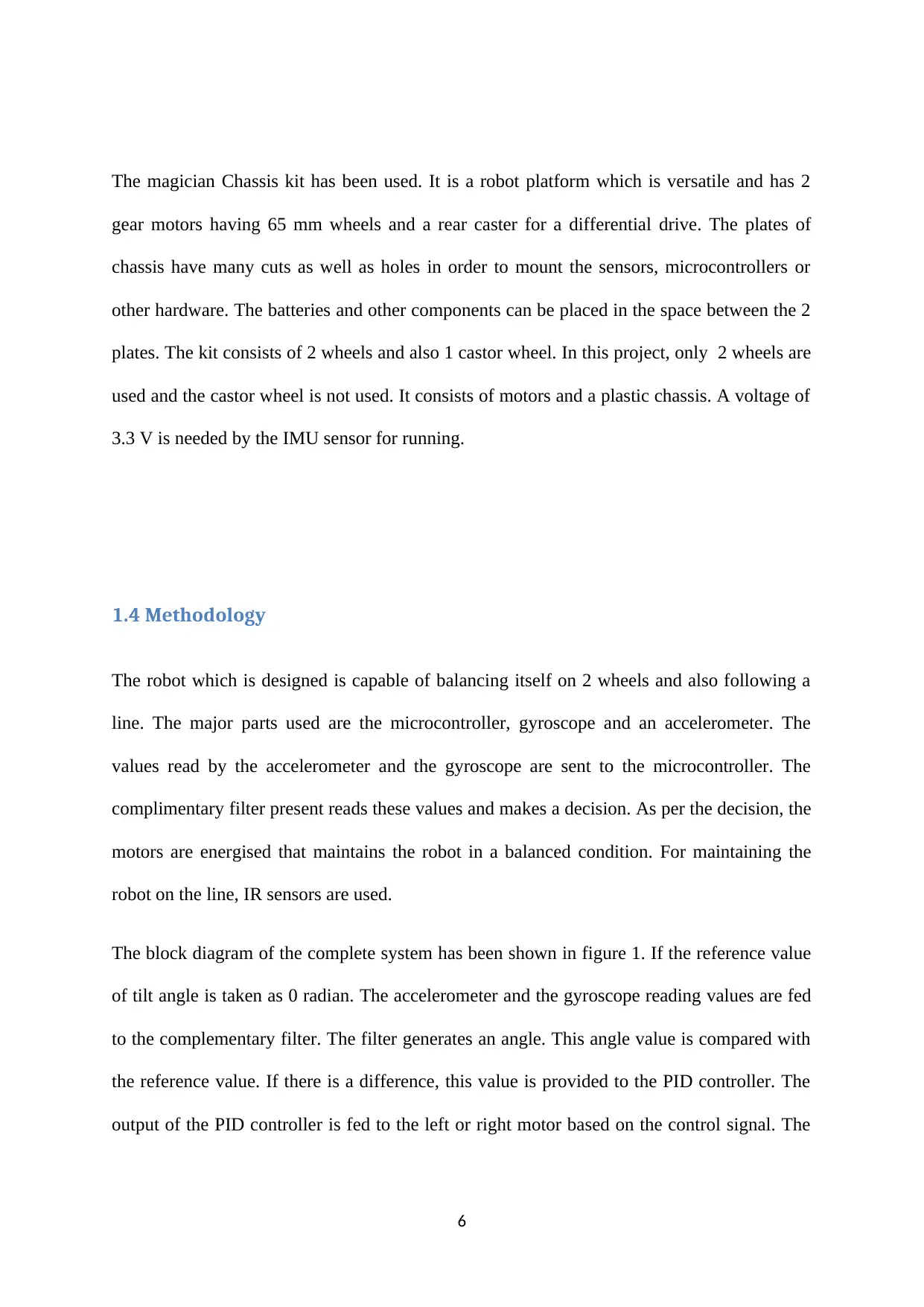
1.4 Methodology
The robot which is designed is capable of balancing itself on 2 wheels and also following a
line. The major parts used are the microcontroller, gyroscope and an accelerometer. The
values read by the accelerometer and the gyroscope are sent to the microcontroller. The
complimentary filter present reads these values and makes a decision. As per the decision, the
motors are energised that maintains the robot in a balanced condition. For maintaining the
robot on the line, IR sensors are used.
The block diagram of the complete system has been shown in figure 1. If the reference value
of tilt angle is taken as 0 radian. The accelerometer and the gyroscope reading values are fed
to the complementary filter. The filter generates an angle. This angle value is compared with
the reference value. If there is a difference, this value is provided to the PID controller. The
output of the PID controller is fed to the left or right motor based on the control signal. The
6
gear motors having 65 mm wheels and a rear caster for a differential drive. The plates of
chassis have many cuts as well as holes in order to mount the sensors, microcontrollers or
other hardware. The batteries and other components can be placed in the space between the 2
plates. The kit consists of 2 wheels and also 1 castor wheel. In this project, only 2 wheels are
used and the castor wheel is not used. It consists of motors and a plastic chassis. A voltage of
3.3 V is needed by the IMU sensor for running.
1.4 Methodology
The robot which is designed is capable of balancing itself on 2 wheels and also following a
line. The major parts used are the microcontroller, gyroscope and an accelerometer. The
values read by the accelerometer and the gyroscope are sent to the microcontroller. The
complimentary filter present reads these values and makes a decision. As per the decision, the
motors are energised that maintains the robot in a balanced condition. For maintaining the
robot on the line, IR sensors are used.
The block diagram of the complete system has been shown in figure 1. If the reference value
of tilt angle is taken as 0 radian. The accelerometer and the gyroscope reading values are fed
to the complementary filter. The filter generates an angle. This angle value is compared with
the reference value. If there is a difference, this value is provided to the PID controller. The
output of the PID controller is fed to the left or right motor based on the control signal. The
6
⊘ This is a preview!⊘
Do you want full access?
Subscribe today to unlock all pages.
Trusted by 1+ million students worldwide
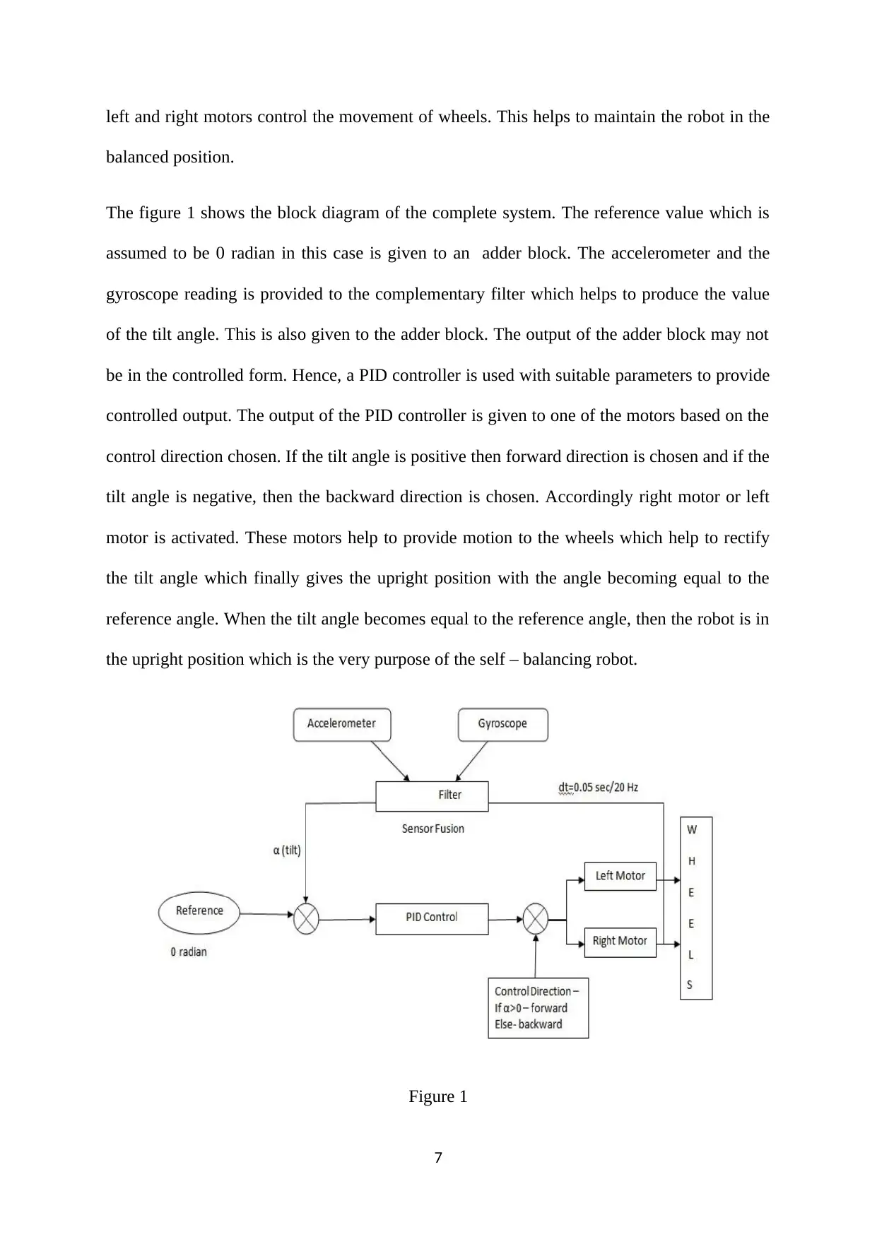
left and right motors control the movement of wheels. This helps to maintain the robot in the
balanced position.
The figure 1 shows the block diagram of the complete system. The reference value which is
assumed to be 0 radian in this case is given to an adder block. The accelerometer and the
gyroscope reading is provided to the complementary filter which helps to produce the value
of the tilt angle. This is also given to the adder block. The output of the adder block may not
be in the controlled form. Hence, a PID controller is used with suitable parameters to provide
controlled output. The output of the PID controller is given to one of the motors based on the
control direction chosen. If the tilt angle is positive then forward direction is chosen and if the
tilt angle is negative, then the backward direction is chosen. Accordingly right motor or left
motor is activated. These motors help to provide motion to the wheels which help to rectify
the tilt angle which finally gives the upright position with the angle becoming equal to the
reference angle. When the tilt angle becomes equal to the reference angle, then the robot is in
the upright position which is the very purpose of the self – balancing robot.
Figure 1
7
Paraphrase This Document
Need a fresh take? Get an instant paraphrase of this document with our AI Paraphraser
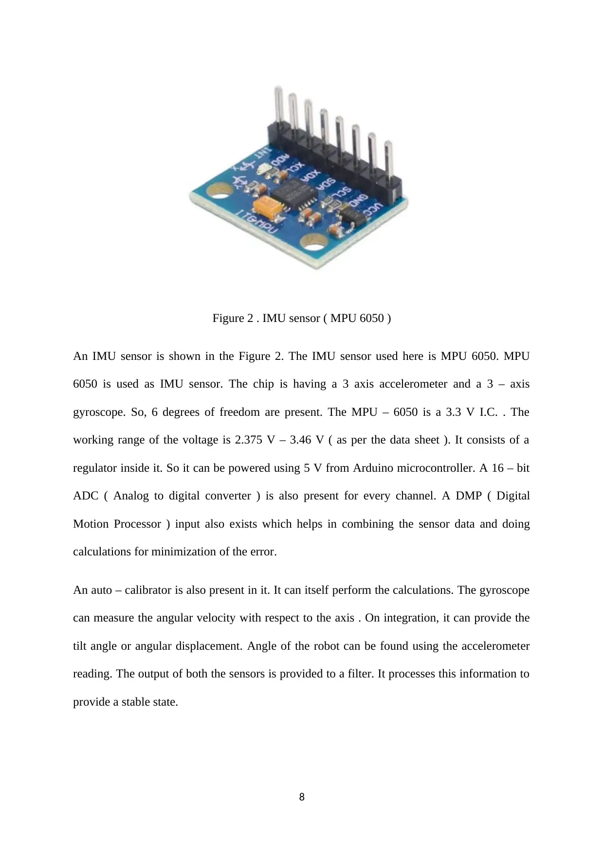
Figure 2 . IMU sensor ( MPU 6050 )
An IMU sensor is shown in the Figure 2. The IMU sensor used here is MPU 6050. MPU
6050 is used as IMU sensor. The chip is having a 3 axis accelerometer and a 3 – axis
gyroscope. So, 6 degrees of freedom are present. The MPU – 6050 is a 3.3 V I.C. . The
working range of the voltage is 2.375 V – 3.46 V ( as per the data sheet ). It consists of a
regulator inside it. So it can be powered using 5 V from Arduino microcontroller. A 16 – bit
ADC ( Analog to digital converter ) is also present for every channel. A DMP ( Digital
Motion Processor ) input also exists which helps in combining the sensor data and doing
calculations for minimization of the error.
An auto – calibrator is also present in it. It can itself perform the calculations. The gyroscope
can measure the angular velocity with respect to the axis . On integration, it can provide the
tilt angle or angular displacement. Angle of the robot can be found using the accelerometer
reading. The output of both the sensors is provided to a filter. It processes this information to
provide a stable state.
8
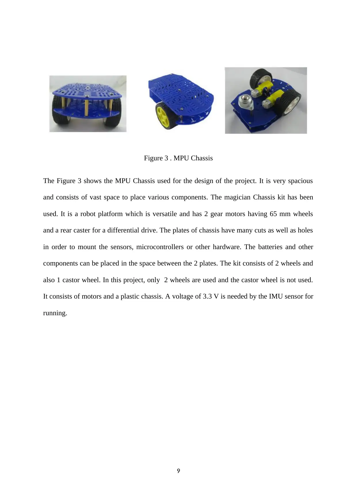
Figure 3 . MPU Chassis
The Figure 3 shows the MPU Chassis used for the design of the project. It is very spacious
and consists of vast space to place various components. The magician Chassis kit has been
used. It is a robot platform which is versatile and has 2 gear motors having 65 mm wheels
and a rear caster for a differential drive. The plates of chassis have many cuts as well as holes
in order to mount the sensors, microcontrollers or other hardware. The batteries and other
components can be placed in the space between the 2 plates. The kit consists of 2 wheels and
also 1 castor wheel. In this project, only 2 wheels are used and the castor wheel is not used.
It consists of motors and a plastic chassis. A voltage of 3.3 V is needed by the IMU sensor for
running.
9
⊘ This is a preview!⊘
Do you want full access?
Subscribe today to unlock all pages.
Trusted by 1+ million students worldwide
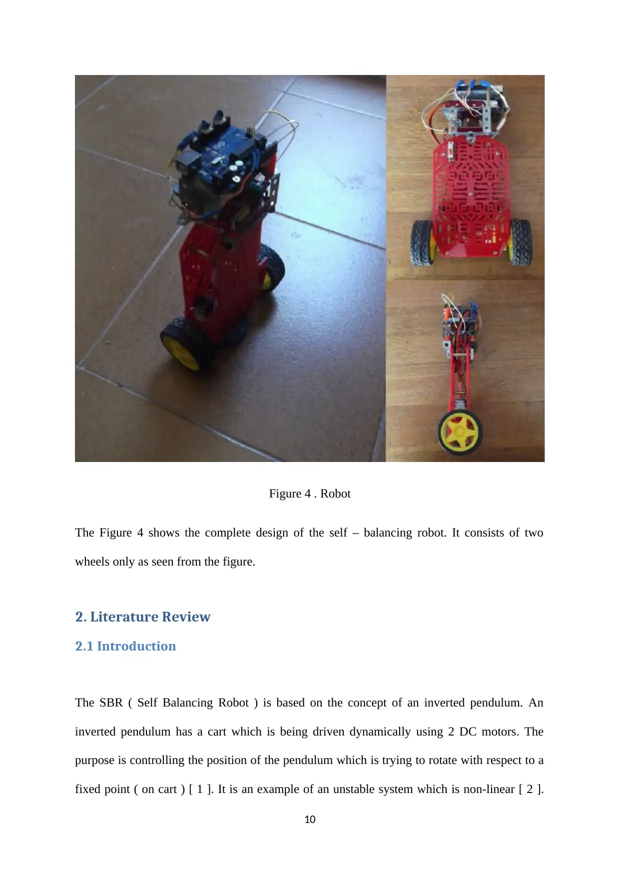
Figure 4 . Robot
The Figure 4 shows the complete design of the self – balancing robot. It consists of two
wheels only as seen from the figure.
2. Literature Review
2.1 Introduction
The SBR ( Self Balancing Robot ) is based on the concept of an inverted pendulum. An
inverted pendulum has a cart which is being driven dynamically using 2 DC motors. The
purpose is controlling the position of the pendulum which is trying to rotate with respect to a
fixed point ( on cart ) [ 1 ]. It is an example of an unstable system which is non-linear [ 2 ].
10
Paraphrase This Document
Need a fresh take? Get an instant paraphrase of this document with our AI Paraphraser
The angle which the pendulum makes with the vertical axis is measured. The angle has to be
maintained at a fixed point with the help of DC motors ( forward or backward drive ) for an
inverted pendulum. The Segway System is a similar one [ 13 ].
The sensor used for the measurement of angle is MPU-6050, IMU ( inertial measurement unit
). The measurement of angle is done by using an accelerometer. It helps to find the angle
between the various forces acting on the inverted pendulum. A gyroscope can be used to
measure the angular velocity which can be integrated to obtain the value of angle of the
pendulum.
The data obtained using the accelerometer and the gyroscope is not error free. This is because
the accelerometer may take into account various other forces which act on the system ( like
frictional force, any vibration due to DC motor ). The error will slowly reduce as the
vibrations slow down. The gyroscope reading has minimum error in the initial time. But as
time passes, then due to integration, error may be seen [ 3 ].
A filter is thus needed to remove these errors. The readings obtained from both the
accelerometer and the gyroscope are combined. A Kalman filter makes use of the 2 readings
and gives an output which does not contain any error [ 4 ]. But the analysis is very tough
[ 14 ]. The integration of the Kalman filter with 8-bit microcontrollers is very difficult. A
solution for this is the use of a complementary filter. It is simple and contains a low pass filter
as well as a high pass filter. It helps to provide angle value which does not contain error. The
various coefficients need to be determined. A PID ( Proportional – Integral – Derivative )
controller is used to obtain Stabilised position of angle [ 5 , 6 , 15 ].
2.2 Inverted Pendulum
The Inverted Pendulum can be modelled to obtain the transfer function as [ 6 ] :
11
. θ ( s ) / X ( s ) = - s2 / l s2 – g
In Laplace Transform form
. θ = Angle of pendulum with vertical axis
l = Length of pendulum
g = acceleration due to gravity
There are 2 platforms available in the robot. There are 4 bolts for supporting them. The
lithium-ion battery ( used for driving the motor ) is placed on upper part and motor driver
circuit is placed on lower part. The Arduino uno microcontroller ( 8 – bit ) , IMU Sensor and
2 DC motors ( 60 rpm ) are fixed on bottom side of the platform. The IMU Sensor needs to
be made immune to any type of vibrations. Hence, it is fixed on bottom side. Generic wheels
are used in the system.
Components:
Arduino Uno Microcontroller- The sensors can be easily interfaced using this
microcontroller. Programming is very easy and cost is less.
IMU Sensor- The IMU sensor based on MEMS technology used here is MPU-6050. It is
given by Inven Sense technologies. It is a 6 Degree of freedom ( DOF ) sensor which
contains 3 gyroscopes as well as 3 accelerometers. The sensor needs a 3.3 V voltage and it
communicates to the microcontroller using the I2C protocol. The motor driver L293 can be
used for driving the motors. The enable pins for both channels are provided with PWM input
obtained by the Arduino microcontroller. The DC motor is used for countering the rotational
12
⊘ This is a preview!⊘
Do you want full access?
Subscribe today to unlock all pages.
Trusted by 1+ million students worldwide
1 out of 53


Your All-in-One AI-Powered Toolkit for Academic Success.
+13062052269
info@desklib.com
Available 24*7 on WhatsApp / Email
![[object Object]](/_next/static/media/star-bottom.7253800d.svg)
Unlock your academic potential
Copyright © 2020–2026 A2Z Services. All Rights Reserved. Developed and managed by ZUCOL.