University Course: Sensor Calibration & Testing Assignment Report

Verified

Added on  2021/04/21

|20
|2459
|151
Practical Assignment
AI Summary
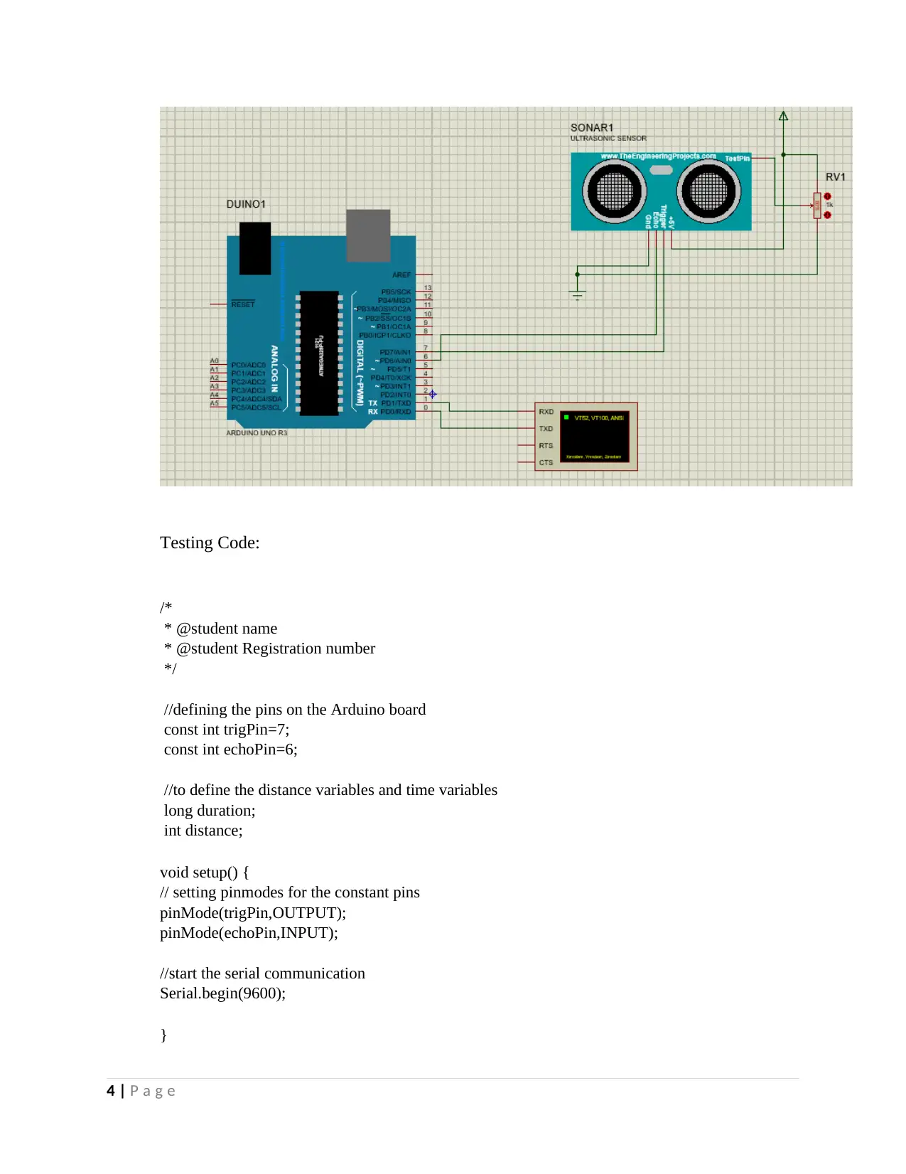
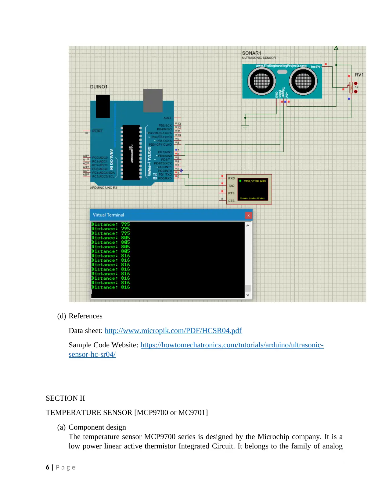
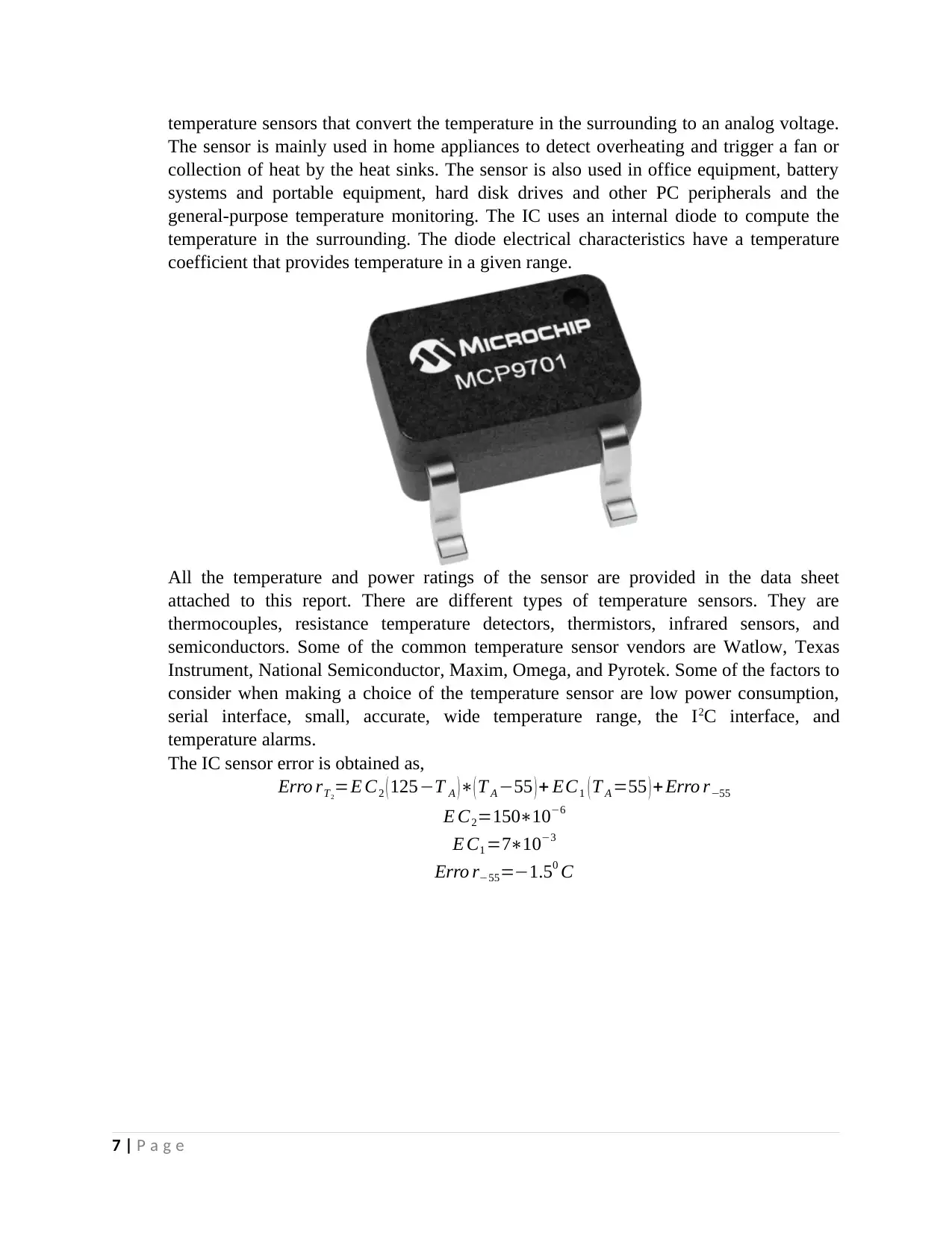
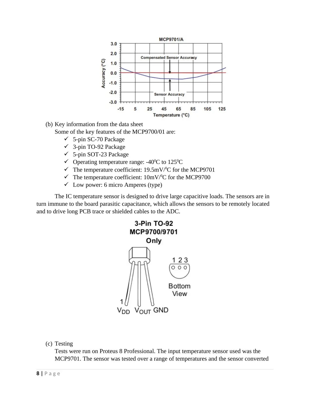
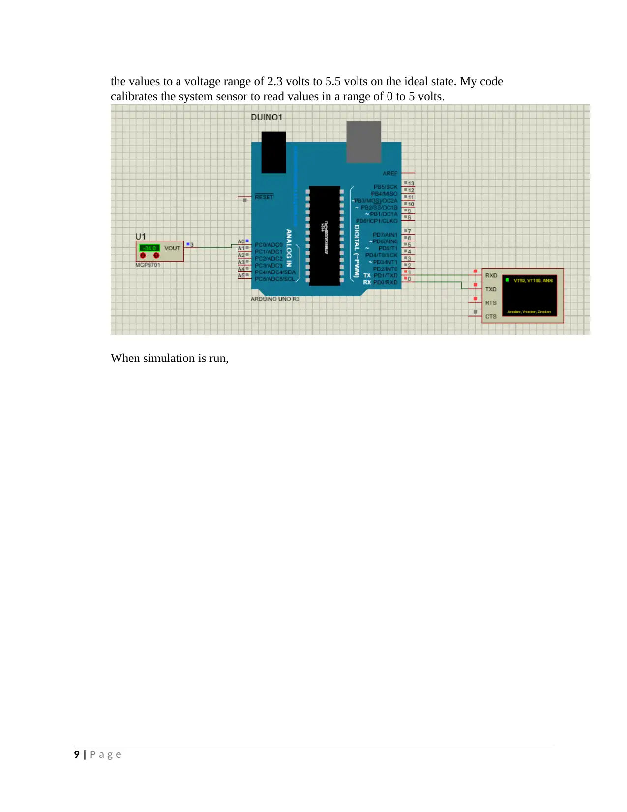
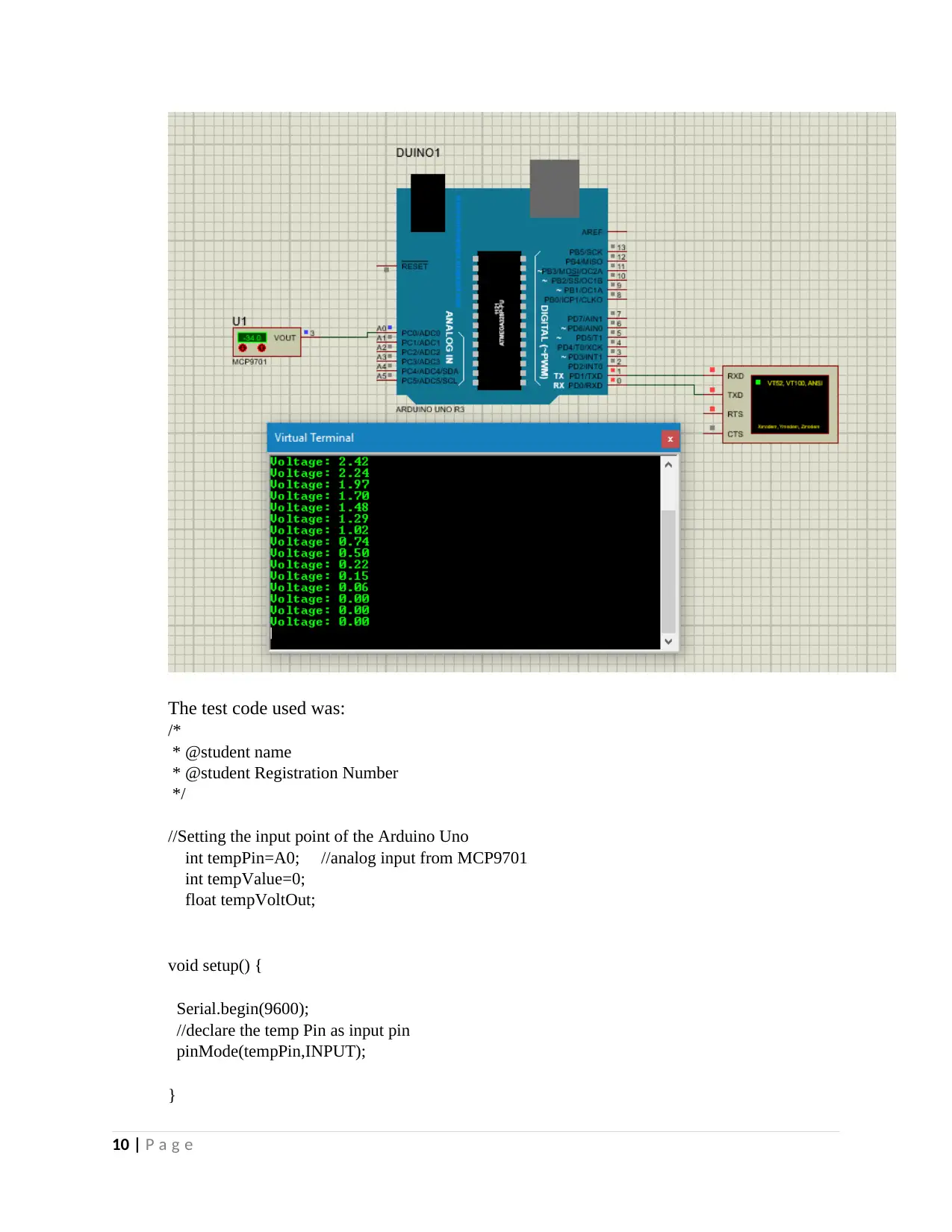
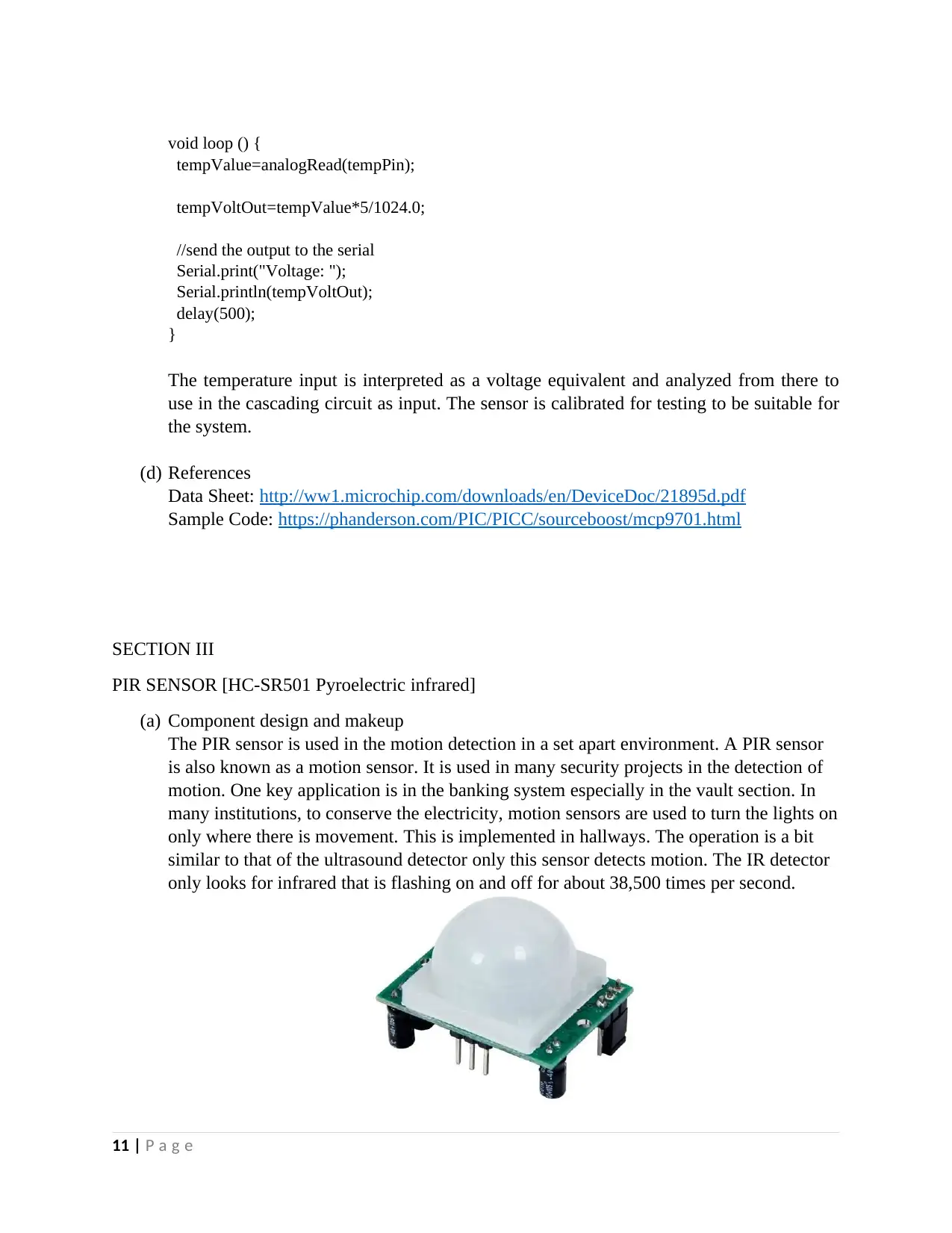
This assignment report details the calibration and testing of various sensors, including the ultrasonic module HC-SR04, temperature sensor MCP9700/9701, PIR sensor HC-SR501, and the TCRT5000 infrared reflective optical sensor. The report includes component descriptions, key information from datasheets, and testing procedures performed using Proteus 8 Professional and Arduino Uno. Each section covers the component design, key features, and testing codes used to analyze the sensor's functionality. The assignment demonstrates how to interface these sensors, interpret their outputs, and calibrate them for specific applications, such as distance measurement, temperature monitoring, motion detection, and object detection. The report also references relevant datasheets and sample code websites for further information.
tabler-icon-diamond-filled.svg

Contribute Materials

Your contribution can guide someone’s learning journey. Share your documents today.
Document Page
UNIVERSITY AFFILIATION
FACULTY OR DEPARTMENT
COURSE NAME
COURSE ID
TITLE:
SENSOR CALIBRATION & TESTING
STUDENT NAME
STUDENT REGISTRATION NUMBER
DATE OF SUBMISSION
tabler-icon-diamond-filled.svg

Secure Best Marks with AI Grader

Need help grading? Try our AI Grader for instant feedback on your assignments.
Document Page
INTRODUCTION
A sensor is a device that acquires a physical parameter and converts it into a signal suitable for
processing. The signal processing could be optical, electrical or even mechanical. Sensors are
embedded in systems and applications with the aim of automating different systems.
Temperature sensors are used in chemical processing plants, automobile engines, appliances, and
other applications that require temperature monitoring. The light sensors are used in cameras,
infrared detectors and ambient lighting applications. The sensors are composed of
photoconductors such as photoresistors, photodiodes, or phototransistors. The ultrasonic sensors
are used for position measurements. The sound waves emitted are done in the frequency range of
2- 15 Megahertz. It uses the Sonar and Radar technology. The photogates are used in counting
applications where one may require to obtain a period of a given motion. The infrared transmitter
and receiver at opposite ends of the sensor and the time at which light is broken is thereafter
recorded.
The American National Standards Institute defines the sensor as a device that provides a usable
output to a specified measured parameter such as,
Stimulus Quantity
Acoustic Wave (amplitude, phase, polarization), Spectrum,
Wave
Velocity
Biological & Chemical Fluid Concentrations (Gas or Liquid)
Electric Charge, Voltage, Current, Electric Field (amplitude,
phase,
polarization), Conductivity, Permittivity
Magnetic Magnetic Field (amplitude, phase, polarization),
Flux,
Permeability
Optical Refractive Index, Reflectivity, Absorption
Thermal Temperature, Flux, Specific Heat, Thermal
Conductivity
Mechanical Position, Velocity, Acceleration, Force, Strain,
Stress,
Pressure, Torque
SECTION I
PING SENSOR [Ultrasonic Module HC-SR04]
(a) Component Description
1 | P a g e
Document Page
Ultrasonic module HC-SR04 is a range finder component that detects objects within a
given range as specified in the datasheet. The interface output formats from the sensor are the
pulse width output, analog voltage output, and serial digital output. The object being detected
needs to be the object closest to the sensor on its path. The ultrasonic module can be referred to
as a sound sensor or a ping sensor. The sensor tends to operate at frequencies higher than those
of human hearing. A human being can hear sound frequencies in the range of 20Hz- 40kHz.
There are two major sections in the sensor, the trigger and the echo. The trigger sends out a
sound wave at a particular frequency. The sensor keeps track of the time between transmission of
the sound wave and the sound wave echo. The distance is, therefore, obtained as
d=vt
These sensors detect sounds using a cone of detection and the cone angle tends to vary with the
distance. The ability to detect an object on the path depends on the object orientation to the
sensor. Any object that does not fall within the range of the sensor cone of detection is not
spotted at all. The effectual angle of the cone of detection is usually at less than 150. The
component can be used to detect objects in a specified range as desired in the project.
(b) Key Information from the data sheet
2 | P a g e
Document Page
Wire connectivity and product features
Power Supply +5V DC
Quiescent Current < 2mA
Working Current 15mA
Effectual Angle <150
Ranging Distance 2-400 cm
Resolution 0.3 cm
Measuring Angle 300
Trigger Input Pulse Width 10μS
Dimensions 45mm x 20 mm x 15mm
Weight ~ 10g
It works by transmitting an ultrasonic burst and providing an output pulse that
corresponds to the time required for the burst echo to return to the sensor. The distance to
the target can easily be calculated by measuring the echo pulse. The PING sensor emits a
short ultrasonic burst and waits for an echo from the echo point. The ultrasonic burst
travels through the air at about 1130 feet per second, hits an object and then bounces back
to the sensor. The PING sensor provides an output pulse to the host that will terminate
when the echo is detected, so that the width of the pulse corresponds to the distance of the
target.
(c) Testing
The tests were carried out in Proteus 8 Professional using the HC-SR04 and the Arduino
Uno and a virtual terminal to display the serial output.
3 | P a g e
tabler-icon-diamond-filled.svg

Secure Best Marks with AI Grader

Need help grading? Try our AI Grader for instant feedback on your assignments.
Document Page
Testing Code:
/*
* @student name
* @student Registration number
*/
//defining the pins on the Arduino board
const int trigPin=7;
const int echoPin=6;
//to define the distance variables and time variables
long duration;
int distance;
void setup() {
// setting pinmodes for the constant pins
pinMode(trigPin,OUTPUT);
pinMode(echoPin,INPUT);
//start the serial communication
Serial.begin(9600);
}
4 | P a g e
Document Page
void loop() {
//inserting the system code here:
digitalWrite(trigPin,LOW);
delayMicroseconds(2);
//to set the trigger Pin ON for some time
digitalWrite(trigPin, HIGH);
delayMicroseconds(10);
digitalWrite(trigPin, LOW);
//Reading input from the test pin using the EchoPin
duration=pulseIn(echoPin,HIGH);
distance=duration*0.034/2;
//Printing out the distance on serial monitor (Virtual Monitor)
Serial.print("Distance");
Serial.print(distance);
}
5 | P a g e
Document Page
(d) References
Data sheet: http://www.micropik.com/PDF/HCSR04.pdf
Sample Code Website: https://howtomechatronics.com/tutorials/arduino/ultrasonic-
sensor-hc-sr04/
SECTION II
TEMPERATURE SENSOR [MCP9700 or MC9701]
(a) Component design
The temperature sensor MCP9700 series is designed by the Microchip company. It is a
low power linear active thermistor Integrated Circuit. It belongs to the family of analog
6 | P a g e
tabler-icon-diamond-filled.svg

Paraphrase This Document

Need a fresh take? Get an instant paraphrase of this document with our AI Paraphraser
Document Page
temperature sensors that convert the temperature in the surrounding to an analog voltage.
The sensor is mainly used in home appliances to detect overheating and trigger a fan or
collection of heat by the heat sinks. The sensor is also used in office equipment, battery
systems and portable equipment, hard disk drives and other PC peripherals and the
general-purpose temperature monitoring. The IC uses an internal diode to compute the
temperature in the surrounding. The diode electrical characteristics have a temperature
coefficient that provides temperature in a given range.
All the temperature and power ratings of the sensor are provided in the data sheet
attached to this report. There are different types of temperature sensors. They are
thermocouples, resistance temperature detectors, thermistors, infrared sensors, and
semiconductors. Some of the common temperature sensor vendors are Watlow, Texas
Instrument, National Semiconductor, Maxim, Omega, and Pyrotek. Some of the factors to
consider when making a choice of the temperature sensor are low power consumption,
serial interface, small, accurate, wide temperature range, the I2C interface, and
temperature alarms.
The IC sensor error is obtained as,
Erro rT2
=E C2 ( 125T A )( T A 55 ) + EC1 ( T A =55 ) + Erro r55
E C2=150106
E C1 =7103
Erro r55=1.50 C
7 | P a g e
Document Page
(b) Key information from the data sheet
Some of the key features of the MCP9700/01 are:
5-pin SC-70 Package
3-pin TO-92 Package
5-pin SOT-23 Package
Operating temperature range: -400C to 1250C
The temperature coefficient: 19.5mV/0C for the MCP9701
The temperature coefficient: 10mV/0C for the MCP9700
Low power: 6 micro Amperes (type)
The IC temperature sensor is designed to drive large capacitive loads. The sensors are in
turn immune to the board parasitic capacitance, which allows the sensors to be remotely located
and to drive long PCB trace or shielded cables to the ADC.
(c) Testing
Tests were run on Proteus 8 Professional. The input temperature sensor used was the
MCP9701. The sensor was tested over a range of temperatures and the sensor converted
8 | P a g e
Document Page
the values to a voltage range of 2.3 volts to 5.5 volts on the ideal state. My code
calibrates the system sensor to read values in a range of 0 to 5 volts.
When simulation is run,
9 | P a g e
tabler-icon-diamond-filled.svg

Secure Best Marks with AI Grader

Need help grading? Try our AI Grader for instant feedback on your assignments.
Document Page
The test code used was:
/*
* @student name
* @student Registration Number
*/
//Setting the input point of the Arduino Uno
int tempPin=A0; //analog input from MCP9701
int tempValue=0;
float tempVoltOut;
void setup() {
Serial.begin(9600);
//declare the temp Pin as input pin
pinMode(tempPin,INPUT);
}
10 | P a g e
Document Page
void loop () {
tempValue=analogRead(tempPin);
tempVoltOut=tempValue*5/1024.0;
//send the output to the serial
Serial.print("Voltage: ");
Serial.println(tempVoltOut);
delay(500);
}
The temperature input is interpreted as a voltage equivalent and analyzed from there to
use in the cascading circuit as input. The sensor is calibrated for testing to be suitable for
the system.
(d) References
Data Sheet: http://ww1.microchip.com/downloads/en/DeviceDoc/21895d.pdf
Sample Code: https://phanderson.com/PIC/PICC/sourceboost/mcp9701.html
SECTION III
PIR SENSOR [HC-SR501 Pyroelectric infrared]
(a) Component design and makeup
The PIR sensor is used in the motion detection in a set apart environment. A PIR sensor
is also known as a motion sensor. It is used in many security projects in the detection of
motion. One key application is in the banking system especially in the vault section. In
many institutions, to conserve the electricity, motion sensors are used to turn the lights on
only where there is movement. This is implemented in hallways. The operation is a bit
similar to that of the ultrasound detector only this sensor detects motion. The IR detector
only looks for infrared that is flashing on and off for about 38,500 times per second.
11 | P a g e
Document Page
The sensor is an Infrared Technology patented by Germany imported LHI778 probe
design. The sensor has an automatic control module, its highly sensitive, highly reliable,
ultra-low voltage operating mode. It finds its application in auto-sensing electrical
equipment especially those that are battery powered automatic controlled products.
(b) Key information from data sheet
Sensitivity (clockwise) 3-7 m
Output timing (clockwise) 3-300 sec
Vcc +5v – 20v
Trigger Methods L- disable repeat trigger, H
enable repeat trigger
Sensing range < 1200, within 7m
Temperature Range -150C to +700C
Delay time Adjustable (3-5 min)
It is applied in the automatic sensing of light for the floor, bathroom, basement, porch,
warehouse, garage, ventilator, and alarm.
(c) Testing
The PIR sensor is interfaced with Arduino Uno in the testing phase.
When there is no motion, the red LED does not light and the Buzzer is off.
12 | P a g e
tabler-icon-diamond-filled.svg

Paraphrase This Document

Need a fresh take? Get an instant paraphrase of this document with our AI Paraphraser
Document Page
When there is motion, the red LED lights and the buzzer goes off or turns ON.
13 | P a g e
Document Page
The test code used is,
#define led 7
#define buzzer 8
#define pirSensor 9
void setup() {
Serial.begin(9600);
pinMode(pirSensor, INPUT);
pinMode(led,OUTPUT);
pinMode(buzzer,OUTPUT);
}
void loop() {
int x= digitalRead(pirSensor);
if(x==LOW)
{
14 | P a g e
Document Page
digitalWrite(led,LOW);
digitalWrite(buzzer,LOW);
Serial.println(x);
}
else
{
digitalWrite(led,HIGH);
digitalWrite(buzzer,HIGH);
Serial.println(x);
}
}
(d) References
Data sheet: https://www.mpja.com/download/31227sc.pdf
Sample Code: https://github.com/ArduinoHocam/PIR-motion_sensor/blob/master/Codes
SECTION IV
TCRT5000 Infrared IR – Infrared Reflective Optical Sensor iRLed & iRNPN [tcrt5000 pair]
(a) Component design and make up
The TCRT5000, TCRT5000L is the reflective optical sensor with transistor output. This
model belongs to a family of reflective sensors which have an infrared emitter and a
phototransistor. The two components are enclosed in a leaded package. The leaded
package is used to block any visible light from reaching the components. The sensor is
released in lead-free soldering and it complies with the set international standards. The
sensor is used as a position sensor for the shaft encoders. It is used to detect reflective
material such as magnetic tapes in ATMS, and it limits switch for mechanical motions in
VCR.
The sensor differs from the ultrasonic sensor and the PIR sensor in that it detects color
and distance. This explains why there is so much caution taken in regards to the sealing
of the package with lead to block any visible light form reaching the emitter. Some
common applications are the line-following robots, auto-data logging on utility meters as
the module can sense if a surface is white or black. It uses an active onboard
potentiometer as the test input to adjust the sensitivity.
15 | P a g e
tabler-icon-diamond-filled.svg

Secure Best Marks with AI Grader

Need help grading? Try our AI Grader for instant feedback on your assignments.
Document Page
The device is designed by the Vishay Industries Electronics. The device is important in
the project in the detection of light changes and color to tell the distance from an
obstacle. Some of the few caveats the design of the system faces are
(i) Real time communication of measurements
(ii) Detection of obstacles based on light is tedious
(iii) It is implemented only in the highly sensitive applications.
(b) Key information from the data sheet
The sensor has many key features where,
Package type Leaded
Detector type Phototransistor
Dimensions 10.2 x 5.8 x 7
Peak operating distance 2.5 mm
Operating range >20%
Relative collector current 0.2 mm to 15 mm
Emitter Wavelength 950 nm
16 | P a g e
Document Page
(c) Testing
Using Proteus 8 professional, the system tests were obtained as,
17 | P a g e
Document Page
The test code used,
/*
*@student name
*@student reg number
*/
int a,b,c;
void setup()
{
Serial.begin(9600);
pinMode(6,OUTPUT);
}
void loop() {
digitalWrite(6,HIGH); // Turning ON LED
delayMicroseconds(500); //wait
a=analogRead(A3); //take reading from photodiode(pin A3) :noise+signal
digitalWrite(6,LOW); //turn Off LED
delayMicroseconds(500); //wait
b=analogRead(A3); // again take reading from photodiode :noise
c=a-b; //taking differnce:[ (noise+signal)-(noise)] just signal
//Serial.print(a); //noise+signal
//Serial.print("\t");
//Serial.print(b); //noise
//Serial.print("\t");
Serial.println(c); // denoised signal
}
When the tests are run or simulating the system we obtained,
18 | P a g e
tabler-icon-diamond-filled.svg

Paraphrase This Document

Need a fresh take? Get an instant paraphrase of this document with our AI Paraphraser
Document Page
The detector has built in optical filters that allow very little light except the 980nm
infrared. It has an electronic filter that only allows signals around 38.5 kHz to pass
through. This prevents IR interference form common sources such as sunlight and indoor
lighting.
(d) References
Data sheet: http://www.mantech.co.za/Datasheets/Products/TCRT5000-8H.pdf
Sample Code: http://www.instructables.com/id/Using-IR-Sensor-TCRT-5000-With-
Arduino-and-Program/
19 | P a g e
chevron_up_icon
1 out of 20
circle_padding
hide_on_mobile
zoom_out_icon
logo.png

Your All-in-One AI-Powered Toolkit for Academic Success.

Available 24*7 on WhatsApp / Email

[object Object]