Demonstrating Physics Understanding: House Wiring Circuit Comparison

Verified

Added on  2022/11/25

|5
|1347
|403
Report
AI Summary
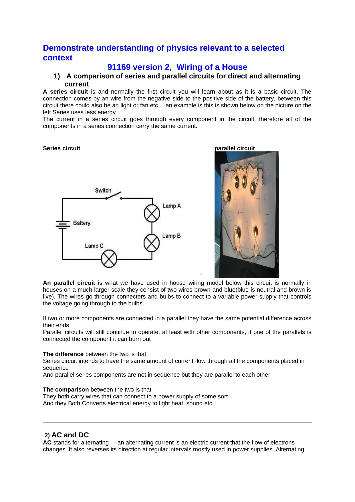
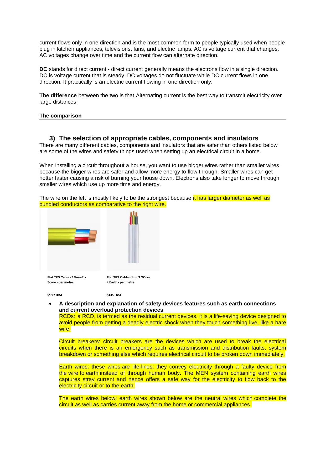
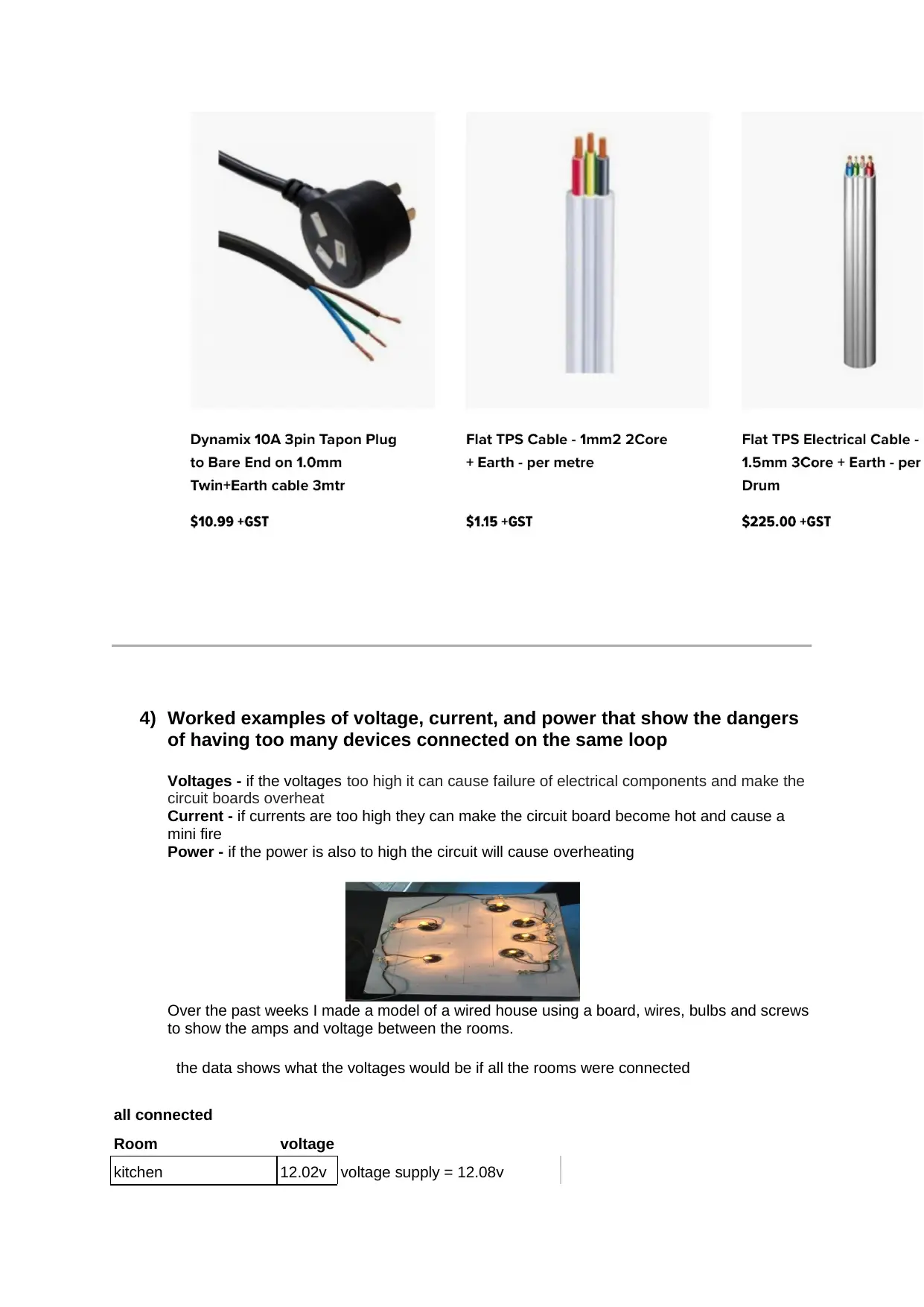
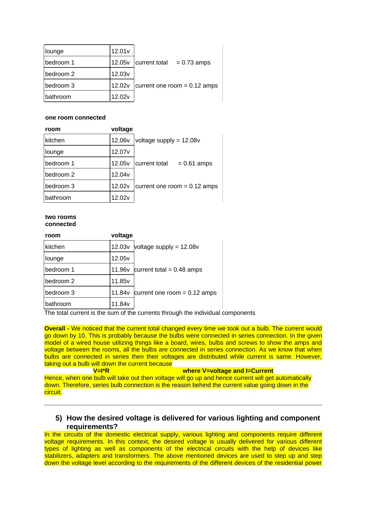
This report provides a comprehensive analysis of house wiring, focusing on the comparison between series and parallel circuits. It explains the fundamental differences between series and parallel circuits, detailing their characteristics and applications within a domestic context. The report also covers alternating current (AC) and direct current (DC), explaining their distinctions and applications. Furthermore, it delves into the selection and importance of appropriate cables, components, and insulators, emphasizing safety considerations. A significant portion of the report is dedicated to describing and explaining various safety devices, including RCDs, circuit breakers, and earth wires, highlighting their roles in preventing electrical hazards. The report includes worked examples of voltage, current, and power, illustrating the dangers of overloading circuits. The student presents data from a house wiring model, analyzing voltage and current measurements across different rooms. Finally, it discusses how desired voltages are delivered for various lighting and component requirements, mentioning the use of stabilizers, adapters, and transformers.
Document Page
Demonstrate understanding of physics relevant to a selected
context
91169 version 2, Wiring of a House
1) A comparison of series and parallel circuits for direct and alternating
current
A series circuit is and normally the first circuit you will learn about as it is a basic circuit. The
connection comes by an wire from the negative side to the positive side of the battery, between this
circuit there could also be an light or fan etc… an example is this is shown below on the picture on the
left Series uses less energy
The current in a series circuit goes through every component in the circuit, therefore all of the
components in a series connection carry the same current.
Series circuit parallel circuit
`
An parallel circuit is what we have used in house wiring model below this circuit is normally in
houses on a much larger scale they consist of two wires brown and blue(blue is neutral and brown is
live). The wires go through connecters and bulbs to connect to a variable power supply that controls
the voltage going through to the bulbs.
If two or more components are connected in a parallel they have the same potential difference across
their ends
Parallel circuits will still continue to operate, at least with other components, if one of the parallels is
connected the component it can burn out
The difference between the two is that
Series circuit intends to have the same amount of current flow through all the components placed in
sequence
And parallel series components are not in sequence but they are parallel to each other
The comparison between the two is that
They both carry wires that can connect to a power supply of some sort
And they Both Converts electrical energy to light heat, sound etc.
2) AC and DC
AC stands for alternating - an alternating current is an electric current that the flow of electrons
changes. It also reverses its direction at regular intervals mostly used in power supplies. Alternating
tabler-icon-diamond-filled.svg

Paraphrase This Document

Need a fresh take? Get an instant paraphrase of this document with our AI Paraphraser
Document Page
current flows only in one direction and is the most common form to people typically used when people
plug in kitchen appliances, televisions, fans, and electric lamps. AC is voltage current that changes.
AC voltages change over time and the current flow can alternate direction.
DC stands for direct current - direct current generally means the electrons flow in a single direction.
DC is voltage current that is steady. DC voltages do not fluctuate while DC current flows in one
direction. It practically is an electric current flowing in one direction only.
The difference between the two is that Alternating current is the best way to transmit electricity over
large distances.
The comparison
3) The selection of appropriate cables, components and insulators
There are many different cables, components and insulators that are safer than others listed below
are some of the wires and safety things used when setting up an electrical circuit in a home.
When installing a circuit throughout a house, you want to use bigger wires rather than smaller wires
because the bigger wires are safer and allow more energy to flow through. Smaller wires can get
hotter faster causing a risk of burning your house down. Electrons also take longer to move through
smaller wires which use up more time and energy.
The wire on the left is mostly likely to be the strongest because it has larger diameter as well as
bundled conductors as comparative to the right wire.
A description and explanation of safety devices features such as earth connections
and current overload protection devices
RCDs: a RCD, is termed as the residual current devices, it is a life-saving device designed to
avoid people from getting a deadly electric shock when they touch something live, like a bare
wire.
Circuit breakers: circuit breakers are the devices which are used to break the electrical
circuits when there is an emergency such as transmission and distribution faults, system
breakdown or something else which requires electrical circuit to be broken down immediately.
Earth wires: these wires are life-lines; they convey electricity through a faulty device from
the wire to earth instead of through human body. The MEN system containing earth wires
captures stray current and hence offers a safe way for the electricity to flow back to the
electricity circuit or to the earth.
The earth wires below: earth wires shown below are the neutral wires which complete the
circuit as well as carries current away from the home or commercial appliances.
Document Page
4) Worked examples of voltage, current, and power that show the dangers
of having too many devices connected on the same loop
Voltages - if the voltages too high it can cause failure of electrical components and make the
circuit boards overheat
Current - if currents are too high they can make the circuit board become hot and cause a
mini fire
Power - if the power is also to high the circuit will cause overheating
Over the past weeks I made a model of a wired house using a board, wires, bulbs and screws
to show the amps and voltage between the rooms.
the data shows what the voltages would be if all the rooms were connected
all connected
Room voltage
kitchen 12.02v voltage supply = 12.08v
Document Page
lounge 12.01v
bedroom 1 12.05v current total = 0.73 amps
bedroom 2 12.03v
bedroom 3 12.02v current one room = 0.12 amps
bathroom 12.02v
one room connected
room voltage
kitchen 12.06v voltage supply = 12.08v
lounge 12.07v
bedroom 1 12.05v current total = 0.61 amps
bedroom 2 12.04v
bedroom 3 12.02v current one room = 0.12 amps
bathroom 12.02v
two rooms
connected
room voltage
kitchen 12.03v voltage supply = 12.08v
lounge 12.05v
bedroom 1 11.96v current total = 0.48 amps
bedroom 2 11.85v
bedroom 3 11.84v current one room = 0.12 amps
bathroom 11.84v
The total current is the sum of the currents through the individual components
Overall - We noticed that the current total changed every time we took out a bulb. The current would
go down by 10. This is probably because the bulbs were connected in series connection. In the given
model of a wired house utilizing things like a board, wires, bulbs and screws to show the amps and
voltage between the rooms, all the bulbs are connected in series connection. As we know that when
bulbs are connected in series then their voltages are distributed while current is same. However,
taking out a bulb will down the current because
V=I*R where V=voltage and I=Current
Hence, when one bulb will take out then voltage will go up and hence current will get automatically
down. Therefore, series bulb connection is the reason behind the current value going down in the
circuit.
5) How the desired voltage is delivered for various lighting and component
requirements?
In the circuits of the domestic electrical supply, various lighting and components require different
voltage requirements. In this context, the desired voltage is usually delivered for various different
types of lighting as well as components of the electrical circuits with the help of devices like
stabilizers, adapters and transformers. The above mentioned devices are used to step up and step
down the voltage level according to the requirements of the different devices of the residential power
tabler-icon-diamond-filled.svg

Paraphrase This Document

Need a fresh take? Get an instant paraphrase of this document with our AI Paraphraser
Document Page
supply circuits. Moreover, the mostly used devices are voltage stabilizers, regulators, adaptors which
are usually used within the domestic circuits otherwise transformers are used.
Resources
https://learn.sparkfun.com/tutorials/series-and-parallel-circuits/all
https://www.quora.com/What-is-the-difference-between-a-series-circuit-and-a-parallel-circuit
https://www.swtc.edu/Ag_Power/electrical/lecture/parallel_circuits.htm
https://www.electricaldirectltd.co.nz/product/17-Flat-TPS-Cable-1-0mm2-2Core-electrical-cable-per-
metre
https://science.howstuffworks.com/electricity7.htm
https://www.physicsclassroom.com/class/estatics
https://electronicsclub.info/power.htm
https://home.howstuffworks.com/induction-cooktops2.htm
https://www.youtube.com/watch?v=sbocWMTmPK8
https://www.slideshare.net/johnwest/series-and-parallel-cir
chevron_up_icon
1 out of 5
circle_padding
hide_on_mobile
zoom_out_icon
[object Object]