Western Sydney University: SFRC Beam Bending Behaviour Thesis
VerifiedAdded on 2022/09/07
|18
|4216
|22
Thesis and Dissertation
AI Summary
This thesis investigates the bending behavior of steel fiber reinforced concrete (SFRC) beams. The study reviews the existing literature on SFRC, focusing on both experimental and modeling methods. Experimental methods discussed include tests conducted by researchers such as Hannant, Noguchi, Hamid, Behzad, and Buttignol, exploring the impact of steel fiber content on flexural strength, crack patterns, and deflection. Modeling methods involve constitutive models and analysis of flexural capacity. The thesis includes detailed descriptions of experimental setups, results, and conclusions drawn from various studies. Key findings highlight the enhanced ductility, increased flexural strength, and reduced crack width observed in SFRC beams compared to traditional reinforced concrete. The research emphasizes the importance of steel fiber volume and its influence on the compressive and tensile properties of concrete. The thesis concludes by summarizing the benefits of SFRC in structural applications and its potential for improving the performance of concrete structures. This research contributes to the body of knowledge on SFRC and its application in civil engineering.
Thesis Title
Bending behaviour of steel fibre
reinforcement concrete beams and model
assignment
Student Name
A thesis submitted for partial fulfilment for the degree of
Bachelor of Engineering (Honours)/
Supervisor(s)
XXXXX
School of Computing Engineering & Mathematics
Western Sydney University
Month, Year
Page 1 of 18
Paraphrase This Document
Need a fresh take? Get an instant paraphrase of this document with our AI Paraphraser
Contents
ABSTRACT..........................................................................................................................................1
LIST OF FICURES...............................................................................................................................1
INTRODUCTION.................................................................................................................................3
Overview...........................................................................................................................................3
Objectives..........................................................................................................................................3
LITERATURE REVIEW......................................................................................................................3
USING EXPERIMENTAL METHODS............................................................................................3
USING MODELLING METHODS..................................................................................................9
Constitutive model for SGR concrete............................................................................................9
Flexural capacity of SFRC...........................................................................................................12
CONCLUSION...................................................................................................................................12
REFERENCES....................................................................................................................................13
LIST OF FICURES
Figure 1. Load versus mid span displacement.......................................................................................4
Figure 2. Hamid beam experiment test setup.........................................................................................5
Figure 3. Load against deflection for fiber reinforced and reinforced concrete.....................................6
Figure 4. Stress strain curve for various reinforcement.........................................................................6
Figure 5. Nominal stress against deflection for 30kg/m3 concrete and 60 kg/m3...................................7
Figure 6. Four point bending test used by Buttignol..............................................................................7
Figure 7. Concrete beam length and sectional properties used by Buttignol in his experiments............8
Figure 8. Pressing force versus deflection of the reinforced and fiber reinforced beam........................8
Figure 9. Compressive stress against strain and tensile stress against strain..........................................9
Figure 10. Schematic diagram of a fiber embedded in concrete..........................................................10
Figure 11. Typical stress-strain response of SFRC in tension..............................................................10
Figure 12. Schematic diagram of SFR concrete section in flexure; stress and strain profile...............12
LIST OF TABLES
Table 1. The mean Value of cube compressive strength according to Hamid........................................4
Table 2. Flexural cracking load and ultimate cracking load for RC and SFARC...................................4
Table 3. Ultimate flexural load and mid span displacement at ultimate tensile load..............................5
Table 4. Number of cracks and crack average width.............................................................................5
Table 5. Buttignol's concrete mixing properties....................................................................................7
LIST OF ABBREVIATIONS
RC: Reinforced Concrete
Page 2 of 18
SF: Steel Fiber.
SFRC: Steel Fiber Reinforced Concrete
LVDT: Linear Variable Differential Transducer
SFARC: Steel Fiber Added Reinforced Concrete.
Page 3 of 18
SFRC: Steel Fiber Reinforced Concrete
LVDT: Linear Variable Differential Transducer
SFARC: Steel Fiber Added Reinforced Concrete.
Page 3 of 18
⊘ This is a preview!⊘
Do you want full access?
Subscribe today to unlock all pages.
Trusted by 1+ million students worldwide
ABSTRACT
Reinforced concrete has been used for various construction works over the years. Numerous materials
and forms have been developed to come up with better concrete that can withstand bigger loads in
both tension and compression. One such material is the steel fiber. The steel fiber arranged randomly
has been proven be superior to the traditional reinforced concrete. This report aims at reviewing the
mechanical bending behaviour of Steel Fiber Reinforced concrete experimentally and using modal
assessment.
Page 4 of 18
Paraphrase This Document
Need a fresh take? Get an instant paraphrase of this document with our AI Paraphraser
STATEMENT OF AUTHENTICATION
This thesis contains no material that has been accepted for the award of any other degree or
diploma and that, to the best of my knowledge and belief, this thesis contains no material
previously published or written by another person, expect when due reference is made in the
text of this thesis.
Signature ................................................. Date ........ /........ /........
Page 5 of 18

ACKNOWLEDGMENT
Page 6 of 18
Page 6 of 18
⊘ This is a preview!⊘
Do you want full access?
Subscribe today to unlock all pages.
Trusted by 1+ million students worldwide
INTRODUCTION
Overview
By far, structural concrete is one of the popularly used building and construction material in the field
of engineering today. Concrete on its own has little ability to withstand strains and stresses without
cracking since it is a brittle material. Reinforcement using steel bars is done to increase the endurance
to stresses and strains of the concrete. The bars are placed at certain critical locations of the beam in a
continuous manner in order to withstand the tensile and compressive loads on the beam. Other
methods of reinforcing the concrete beams is by using fibers. Fibers forms a short, randomly
distributed and discontinuous reinforcements in the concrete structure. Concrete that has been
reinforced using fibers is called Fiber Reinforced Concrete. The most common fibers used in the
world is the Steel Fiber (SF). Concrete reinforced with SF are called Steel Fiber Reinforced Concrete
(SFRC) or Steel Fiber Added Concrete (SFAC) beams.
Steel fibers are used to control the shrinkage of concrete during drying process and the plastic
deformation of the beam by improving on the toughness of the beams, the capacity of absorbing the
strain energy, improving the ductility of the beam before fracturing, improving on durability by
reducing formation of cracks.
Beams reinforced with SF have numerous application such as in building bridges, slabs, dams, decks,
slope stabilization, tunnel linings. It is also used for retrofitting against earthquakes, construction of
marine vessels, pipelines and sewaline construction, fire protection coatings and many other
applications where huge live loads are incurred.
Objectives
This report aims at describing the bending behaviour of the steel fiber reinforced concrete.
LITERATURE REVIEW
USING EXPERIMENTAL METHODS.
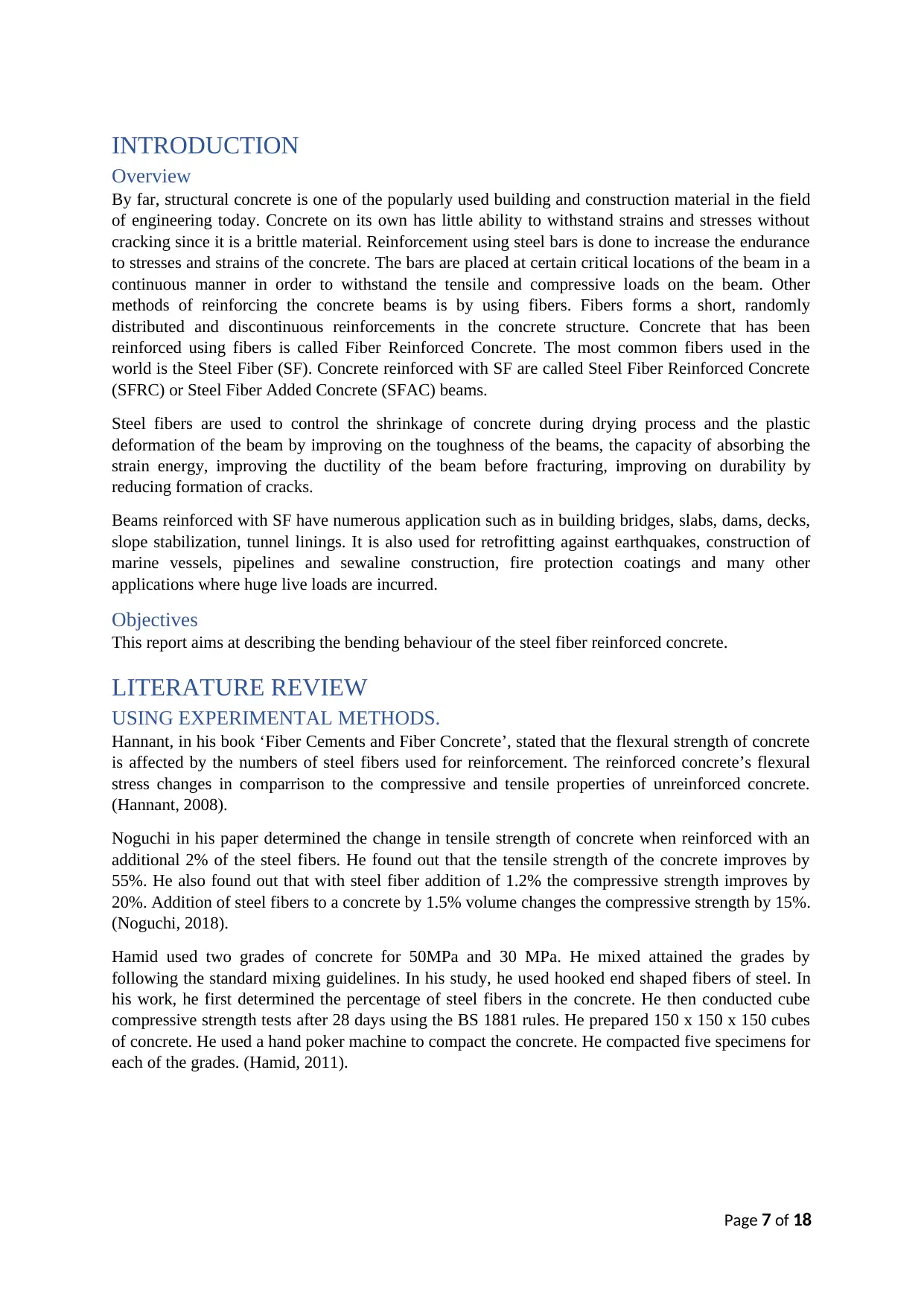
Hannant, in his book ‘Fiber Cements and Fiber Concrete’, stated that the flexural strength of concrete
is affected by the numbers of steel fibers used for reinforcement. The reinforced concrete’s flexural
stress changes in comparrison to the compressive and tensile properties of unreinforced concrete.
(Hannant, 2008).
Noguchi in his paper determined the change in tensile strength of concrete when reinforced with an
additional 2% of the steel fibers. He found out that the tensile strength of the concrete improves by
55%. He also found out that with steel fiber addition of 1.2% the compressive strength improves by
20%. Addition of steel fibers to a concrete by 1.5% volume changes the compressive strength by 15%.
(Noguchi, 2018).
Hamid used two grades of concrete for 50MPa and 30 MPa. He mixed attained the grades by
following the standard mixing guidelines. In his study, he used hooked end shaped fibers of steel. In
his work, he first determined the percentage of steel fibers in the concrete. He then conducted cube
compressive strength tests after 28 days using the BS 1881 rules. He prepared 150 x 150 x 150 cubes
of concrete. He used a hand poker machine to compact the concrete. He compacted five specimens for
each of the grades. (Hamid, 2011).
Page 7 of 18
Overview
By far, structural concrete is one of the popularly used building and construction material in the field
of engineering today. Concrete on its own has little ability to withstand strains and stresses without
cracking since it is a brittle material. Reinforcement using steel bars is done to increase the endurance
to stresses and strains of the concrete. The bars are placed at certain critical locations of the beam in a
continuous manner in order to withstand the tensile and compressive loads on the beam. Other
methods of reinforcing the concrete beams is by using fibers. Fibers forms a short, randomly
distributed and discontinuous reinforcements in the concrete structure. Concrete that has been
reinforced using fibers is called Fiber Reinforced Concrete. The most common fibers used in the
world is the Steel Fiber (SF). Concrete reinforced with SF are called Steel Fiber Reinforced Concrete
(SFRC) or Steel Fiber Added Concrete (SFAC) beams.
Steel fibers are used to control the shrinkage of concrete during drying process and the plastic
deformation of the beam by improving on the toughness of the beams, the capacity of absorbing the
strain energy, improving the ductility of the beam before fracturing, improving on durability by
reducing formation of cracks.
Beams reinforced with SF have numerous application such as in building bridges, slabs, dams, decks,
slope stabilization, tunnel linings. It is also used for retrofitting against earthquakes, construction of
marine vessels, pipelines and sewaline construction, fire protection coatings and many other
applications where huge live loads are incurred.
Objectives
This report aims at describing the bending behaviour of the steel fiber reinforced concrete.
LITERATURE REVIEW
USING EXPERIMENTAL METHODS.
Hannant, in his book ‘Fiber Cements and Fiber Concrete’, stated that the flexural strength of concrete
is affected by the numbers of steel fibers used for reinforcement. The reinforced concrete’s flexural
stress changes in comparrison to the compressive and tensile properties of unreinforced concrete.
(Hannant, 2008).
Noguchi in his paper determined the change in tensile strength of concrete when reinforced with an
additional 2% of the steel fibers. He found out that the tensile strength of the concrete improves by
55%. He also found out that with steel fiber addition of 1.2% the compressive strength improves by
20%. Addition of steel fibers to a concrete by 1.5% volume changes the compressive strength by 15%.
(Noguchi, 2018).
Hamid used two grades of concrete for 50MPa and 30 MPa. He mixed attained the grades by
following the standard mixing guidelines. In his study, he used hooked end shaped fibers of steel. In
his work, he first determined the percentage of steel fibers in the concrete. He then conducted cube
compressive strength tests after 28 days using the BS 1881 rules. He prepared 150 x 150 x 150 cubes
of concrete. He used a hand poker machine to compact the concrete. He compacted five specimens for
each of the grades. (Hamid, 2011).
Page 7 of 18
Paraphrase This Document
Need a fresh take? Get an instant paraphrase of this document with our AI Paraphraser
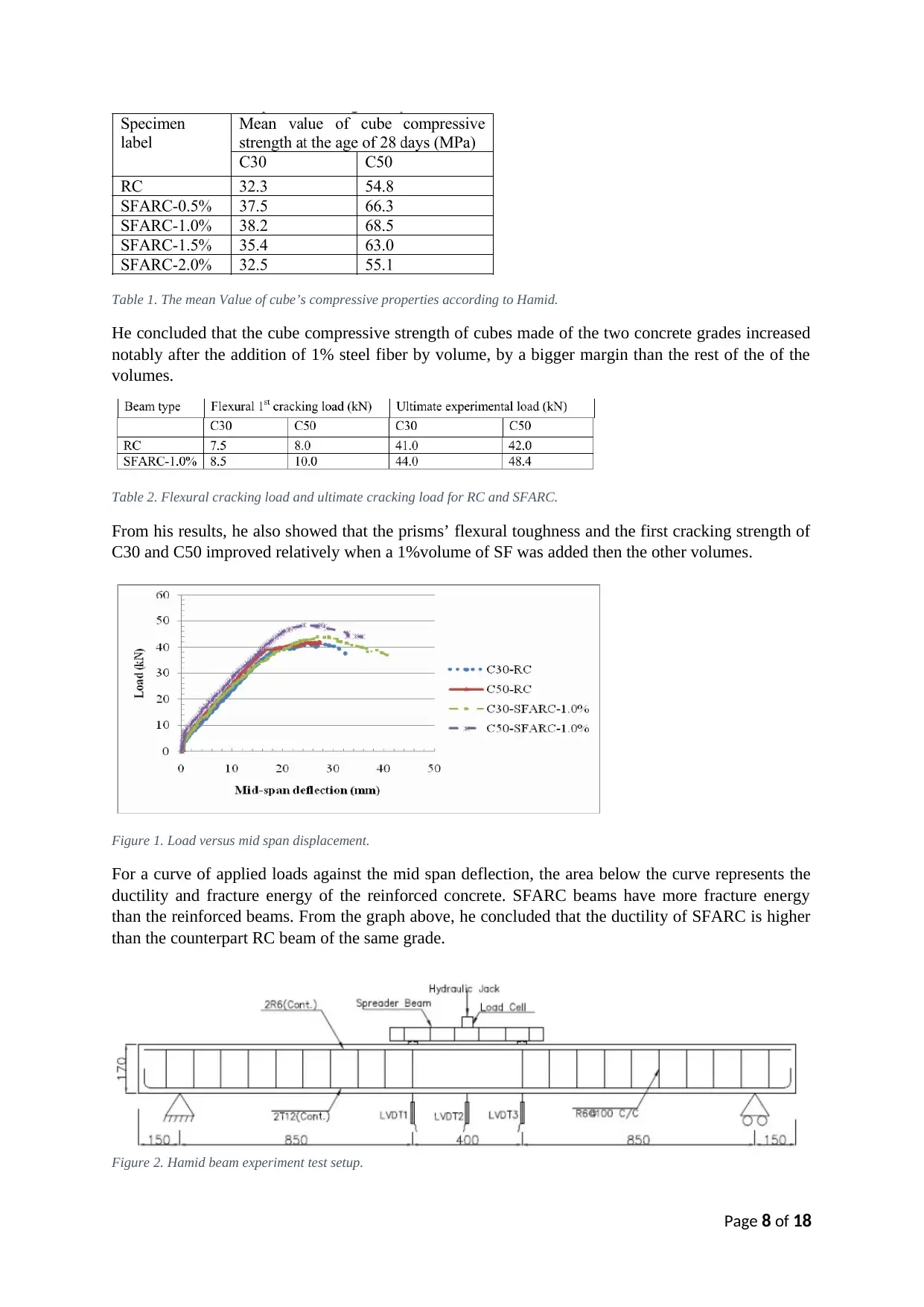
Table 1. The mean Value of cube’s compressive properties according to Hamid.
He concluded that the cube compressive strength of cubes made of the two concrete grades increased
notably after the addition of 1% steel fiber by volume, by a bigger margin than the rest of the of the
volumes.
Table 2. Flexural cracking load and ultimate cracking load for RC and SFARC.
From his results, he also showed that the prisms’ flexural toughness and the first cracking strength of
C30 and C50 improved relatively when a 1%volume of SF was added then the other volumes.
Figure 1. Load versus mid span displacement.
For a curve of applied loads against the mid span deflection, the area below the curve represents the
ductility and fracture energy of the reinforced concrete. SFARC beams have more fracture energy
than the reinforced beams. From the graph above, he concluded that the ductility of SFARC is higher
than the counterpart RC beam of the same grade.
Figure 2. Hamid beam experiment test setup.
Page 8 of 18
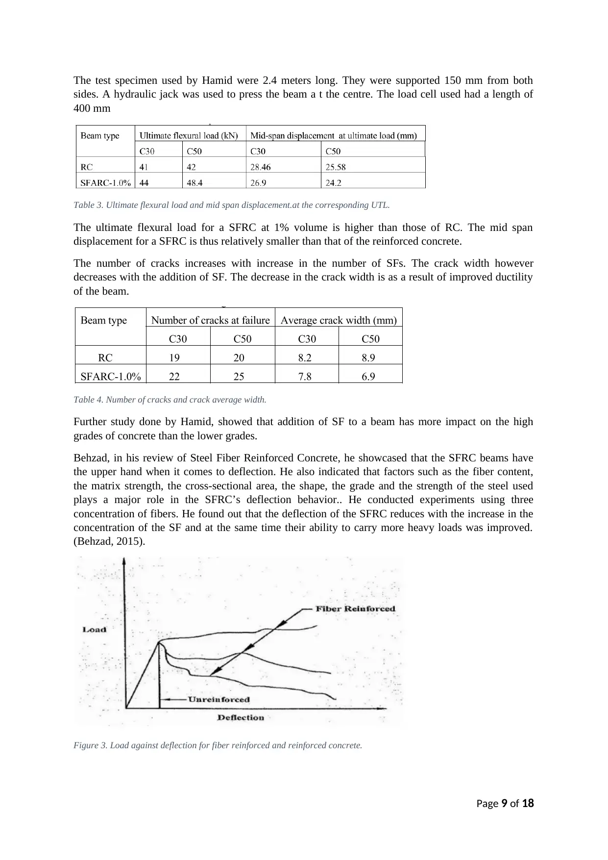
The test specimen used by Hamid were 2.4 meters long. They were supported 150 mm from both
sides. A hydraulic jack was used to press the beam a t the centre. The load cell used had a length of
400 mm
Table 3. Ultimate flexural load and mid span displacement.at the corresponding UTL.
The ultimate flexural load for a SFRC at 1% volume is higher than those of RC. The mid span
displacement for a SFRC is thus relatively smaller than that of the reinforced concrete.
The number of cracks increases with increase in the number of SFs. The crack width however
decreases with the addition of SF. The decrease in the crack width is as a result of improved ductility
of the beam.
Table 4. Number of cracks and crack average width.
Further study done by Hamid, showed that addition of SF to a beam has more impact on the high
grades of concrete than the lower grades.
Behzad, in his review of Steel Fiber Reinforced Concrete, he showcased that the SFRC beams have
the upper hand when it comes to deflection. He also indicated that factors such as the fiber content,
the matrix strength, the cross-sectional area, the shape, the grade and the strength of the steel used
plays a major role in the SFRC’s deflection behavior.. He conducted experiments using three
concentration of fibers. He found out that the deflection of the SFRC reduces with the increase in the
concentration of the SF and at the same time their ability to carry more heavy loads was improved.
(Behzad, 2015).
Figure 3. Load against deflection for fiber reinforced and reinforced concrete.
Page 9 of 18
⊘ This is a preview!⊘
Do you want full access?
Subscribe today to unlock all pages.
Trusted by 1+ million students worldwide
Behzad pointed out that the addition of SF on beams however reduces their workability due to the
increase in the stiffness of the beam.
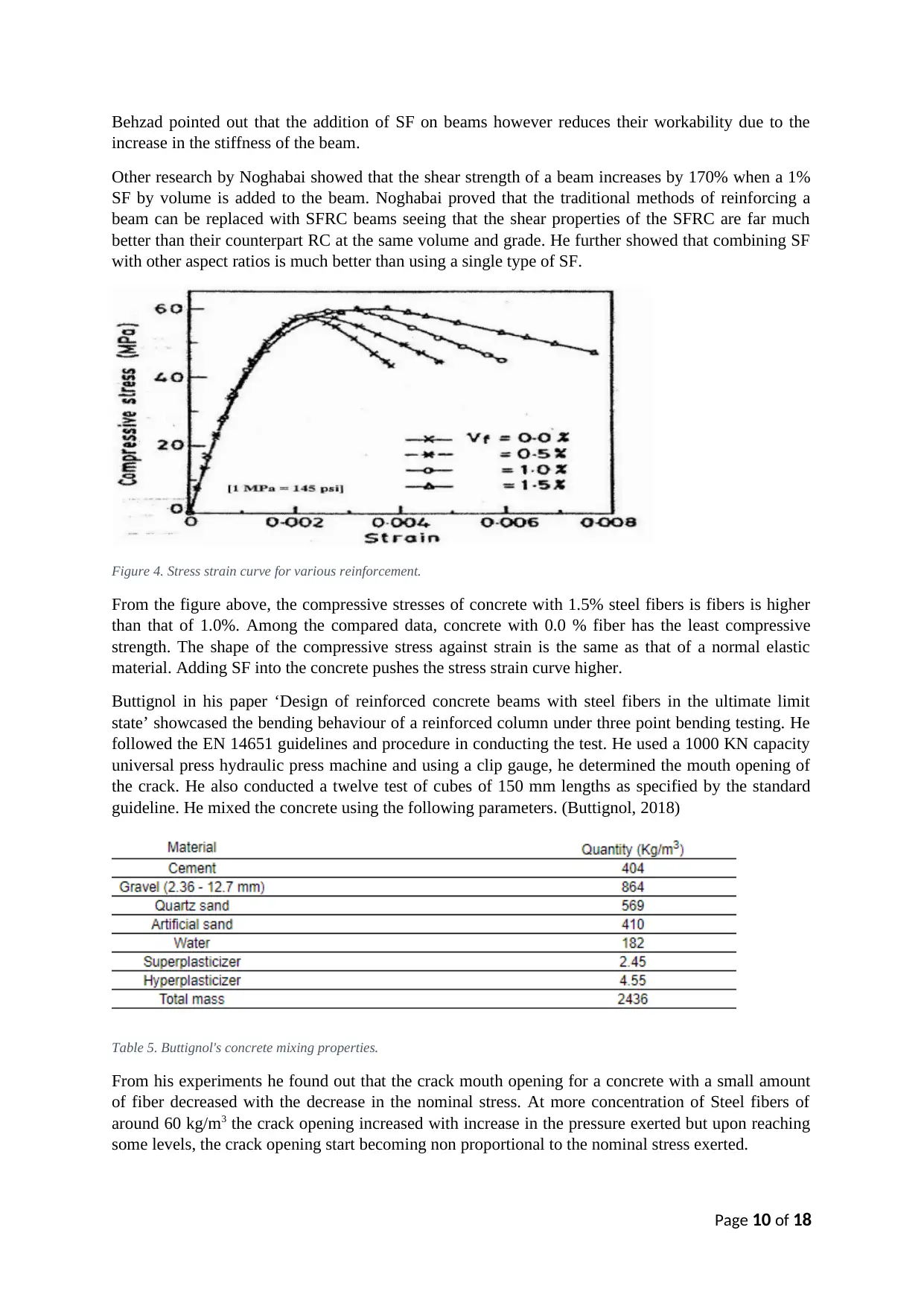
Other research by Noghabai showed that the shear strength of a beam increases by 170% when a 1%
SF by volume is added to the beam. Noghabai proved that the traditional methods of reinforcing a
beam can be replaced with SFRC beams seeing that the shear properties of the SFRC are far much
better than their counterpart RC at the same volume and grade. He further showed that combining SF
with other aspect ratios is much better than using a single type of SF.
Figure 4. Stress strain curve for various reinforcement.
From the figure above, the compressive stresses of concrete with 1.5% steel fibers is fibers is higher
than that of 1.0%. Among the compared data, concrete with 0.0 % fiber has the least compressive
strength. The shape of the compressive stress against strain is the same as that of a normal elastic
material. Adding SF into the concrete pushes the stress strain curve higher.
Buttignol in his paper ‘Design of reinforced concrete beams with steel fibers in the ultimate limit
state’ showcased the bending behaviour of a reinforced column under three point bending testing. He
followed the EN 14651 guidelines and procedure in conducting the test. He used a 1000 KN capacity
universal press hydraulic press machine and using a clip gauge, he determined the mouth opening of
the crack. He also conducted a twelve test of cubes of 150 mm lengths as specified by the standard
guideline. He mixed the concrete using the following parameters. (Buttignol, 2018)
Table 5. Buttignol's concrete mixing properties.
From his experiments he found out that the crack mouth opening for a concrete with a small amount
of fiber decreased with the decrease in the nominal stress. At more concentration of Steel fibers of
around 60 kg/m3 the crack opening increased with increase in the pressure exerted but upon reaching
some levels, the crack opening start becoming non proportional to the nominal stress exerted.
Page 10 of 18
increase in the stiffness of the beam.
Other research by Noghabai showed that the shear strength of a beam increases by 170% when a 1%
SF by volume is added to the beam. Noghabai proved that the traditional methods of reinforcing a
beam can be replaced with SFRC beams seeing that the shear properties of the SFRC are far much
better than their counterpart RC at the same volume and grade. He further showed that combining SF
with other aspect ratios is much better than using a single type of SF.
Figure 4. Stress strain curve for various reinforcement.
From the figure above, the compressive stresses of concrete with 1.5% steel fibers is fibers is higher
than that of 1.0%. Among the compared data, concrete with 0.0 % fiber has the least compressive
strength. The shape of the compressive stress against strain is the same as that of a normal elastic
material. Adding SF into the concrete pushes the stress strain curve higher.
Buttignol in his paper ‘Design of reinforced concrete beams with steel fibers in the ultimate limit
state’ showcased the bending behaviour of a reinforced column under three point bending testing. He
followed the EN 14651 guidelines and procedure in conducting the test. He used a 1000 KN capacity
universal press hydraulic press machine and using a clip gauge, he determined the mouth opening of
the crack. He also conducted a twelve test of cubes of 150 mm lengths as specified by the standard
guideline. He mixed the concrete using the following parameters. (Buttignol, 2018)
Table 5. Buttignol's concrete mixing properties.
From his experiments he found out that the crack mouth opening for a concrete with a small amount
of fiber decreased with the decrease in the nominal stress. At more concentration of Steel fibers of
around 60 kg/m3 the crack opening increased with increase in the pressure exerted but upon reaching
some levels, the crack opening start becoming non proportional to the nominal stress exerted.
Page 10 of 18
Paraphrase This Document
Need a fresh take? Get an instant paraphrase of this document with our AI Paraphraser
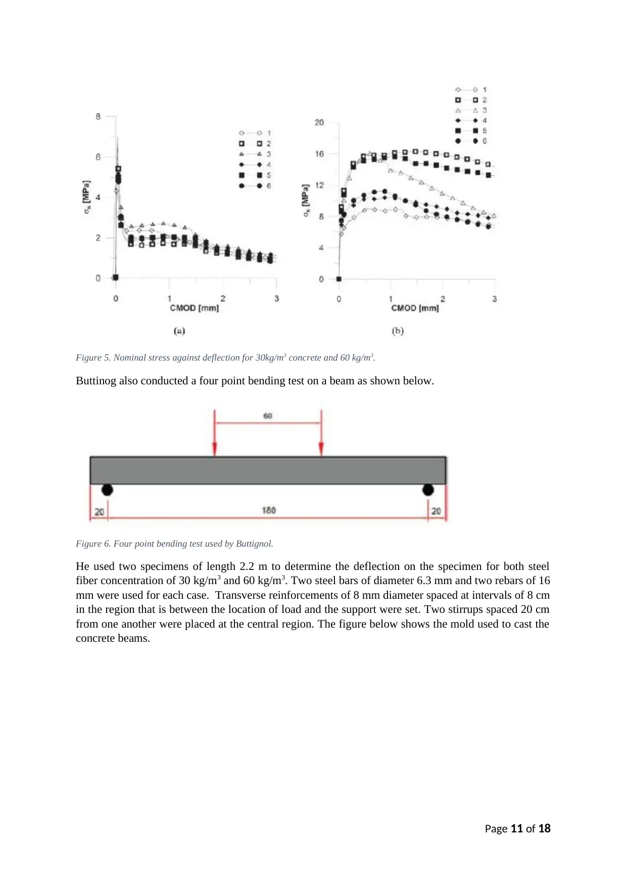
Figure 5. Nominal stress against deflection for 30kg/m3 concrete and 60 kg/m3.
Buttinog also conducted a four point bending test on a beam as shown below.
Figure 6. Four point bending test used by Buttignol.
He used two specimens of length 2.2 m to determine the deflection on the specimen for both steel
fiber concentration of 30 kg/m3 and 60 kg/m3. Two steel bars of diameter 6.3 mm and two rebars of 16
mm were used for each case. Transverse reinforcements of 8 mm diameter spaced at intervals of 8 cm
in the region that is between the location of load and the support were set. Two stirrups spaced 20 cm
from one another were placed at the central region. The figure below shows the mold used to cast the
concrete beams.
Page 11 of 18
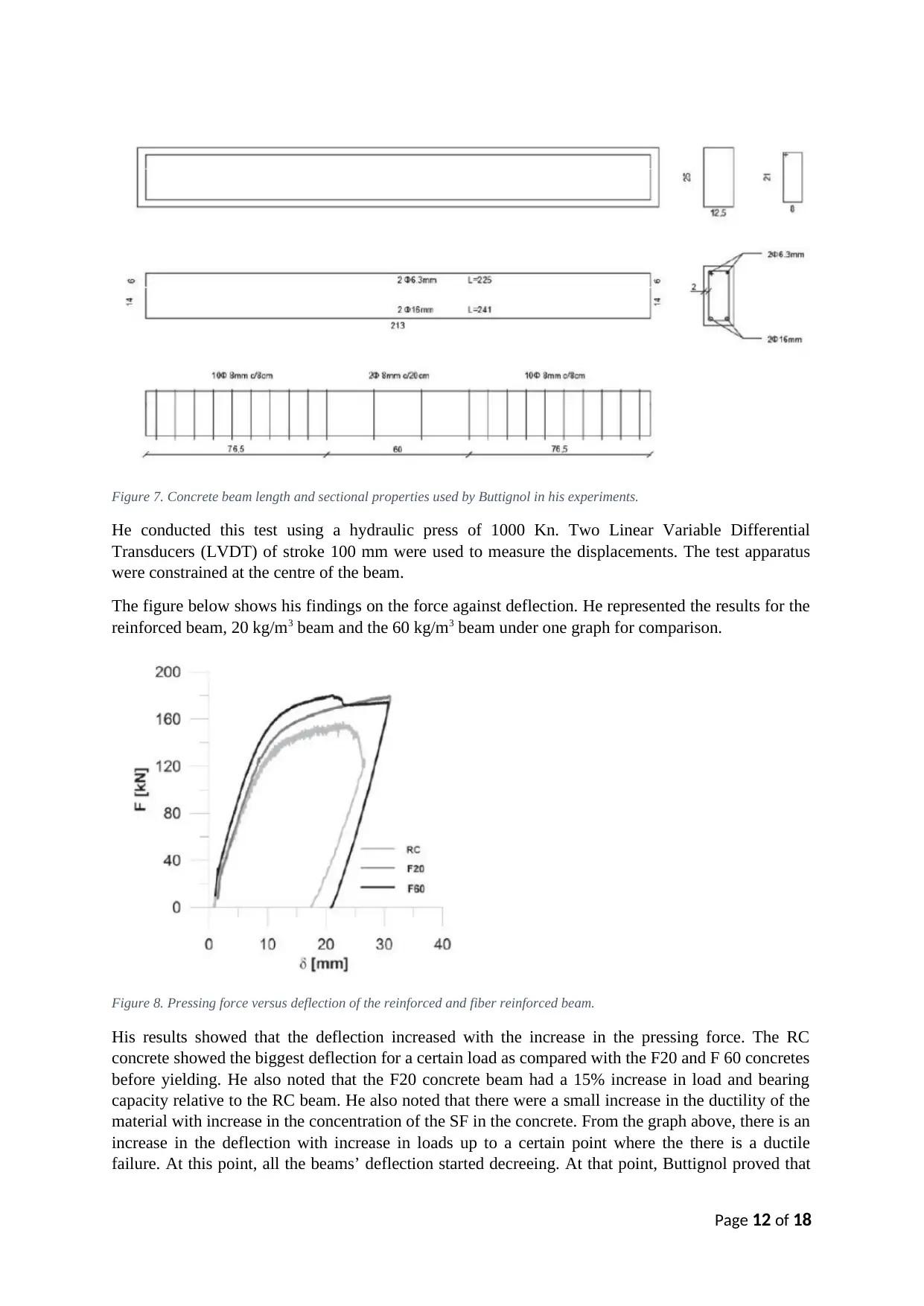
Figure 7. Concrete beam length and sectional properties used by Buttignol in his experiments.
He conducted this test using a hydraulic press of 1000 Kn. Two Linear Variable Differential
Transducers (LVDT) of stroke 100 mm were used to measure the displacements. The test apparatus
were constrained at the centre of the beam.
The figure below shows his findings on the force against deflection. He represented the results for the
reinforced beam, 20 kg/m3 beam and the 60 kg/m3 beam under one graph for comparison.
Figure 8. Pressing force versus deflection of the reinforced and fiber reinforced beam.
His results showed that the deflection increased with the increase in the pressing force. The RC
concrete showed the biggest deflection for a certain load as compared with the F20 and F 60 concretes
before yielding. He also noted that the F20 concrete beam had a 15% increase in load and bearing
capacity relative to the RC beam. He also noted that there were a small increase in the ductility of the
material with increase in the concentration of the SF in the concrete. From the graph above, there is an
increase in the deflection with increase in loads up to a certain point where the there is a ductile
failure. At this point, all the beams’ deflection started decreeing. At that point, Buttignol proved that
Page 12 of 18
⊘ This is a preview!⊘
Do you want full access?
Subscribe today to unlock all pages.
Trusted by 1+ million students worldwide
1 out of 18
Related Documents


Your All-in-One AI-Powered Toolkit for Academic Success.
+13062052269
info@desklib.com
Available 24*7 on WhatsApp / Email
![[object Object]](/_next/static/media/star-bottom.7253800d.svg)
Unlock your academic potential
Copyright © 2020–2026 A2Z Services. All Rights Reserved. Developed and managed by ZUCOL.