Comprehensive Lab Report: Experimental Analysis of Shear Force
VerifiedAdded on 2023/06/15
|20
|4671
|360
Report
AI Summary
This lab report details an experiment conducted to calculate shear force at the cut section of a beam using a spring balance and various weights. The experiment involved applying different weight sets to the beam at various locations, conducting four tests, and recording shear force using a spring balance. The experimental shear force values were obtained by subtracting the datum force from the actual force measured with weights. Theoretical calculations were performed for the same conditions, and the results were compared with the experimental values, showing a slight difference of approximately 8%. The report includes an introduction, background theory, equipment used, experimental procedure, results, theoretical calculations, discussion, conclusion, and recommendations, covering topics such as reactions at supports, shear force and bending moment calculations across different beam spans.
SHEAR FORCE LAB REPORT
REPORT
ON
SHEAR FORCE ON A BEAM
1 | P a g e
REPORT
ON
SHEAR FORCE ON A BEAM
1 | P a g e
Paraphrase This Document
Need a fresh take? Get an instant paraphrase of this document with our AI Paraphraser

SHEAR FORCE LAB REPORT
ABSTRACT
In this experiment, a complete set up is done to calculate the shear force at
the cut section in beam. For that purpose different sets of weight are tested on
the beams at different location. Four test were conducted and from spring
balance , the shear force in all those cases were obtained by subtracting the
datum force on balance to the actual force obtained using weights. Then the
theoretical calculations are done for same condition as in four cases. The result
obtained in actual calculation and experimental calculation were slightly
different by around 8 %.
2 | P a g e
SHEAR FORCE LAB REPORT
Table of Contents................................................................................................3
1. Introduction..............................................................................................4
2. Background theory...................................................................................4
3. Equipment used........................................................................................4
4. Experimental procedure...........................................................................5
5. Results......................................................................................................6
6. Theoritical calculation..............................................................................7
7 Discussion..............................................................................................18
8. Conclusion.............................................................................................18
9. Recommendations..................................................................................19
10. Reference...............................................................................................19
3 | P a g e
⊘ This is a preview!⊘
Do you want full access?
Subscribe today to unlock all pages.
Trusted by 1+ million students worldwide

SHEAR FORCE LAB REPORT
INTRODUCTION
AIM /OBJECTIVE
The main aim for this experiment is to calculate the shear force at the cut section of beam
using spring balance and multiple weights and compare the obtained experimental value
with the theoretical calculation .
BACKGROUND THEORY
The main theory behind this experiment is when a beam is supported at its ends and force
or load applied on it from the top then a resultant force act on each part of beam along its
length . This resultant force called shear force . Beam also observe bending moment .
Bending moment is product of shear force and displacement along the length of beam.
Units of Bending moment is Nm (Newton meter) and shear force is Newton( Nash , 1998).
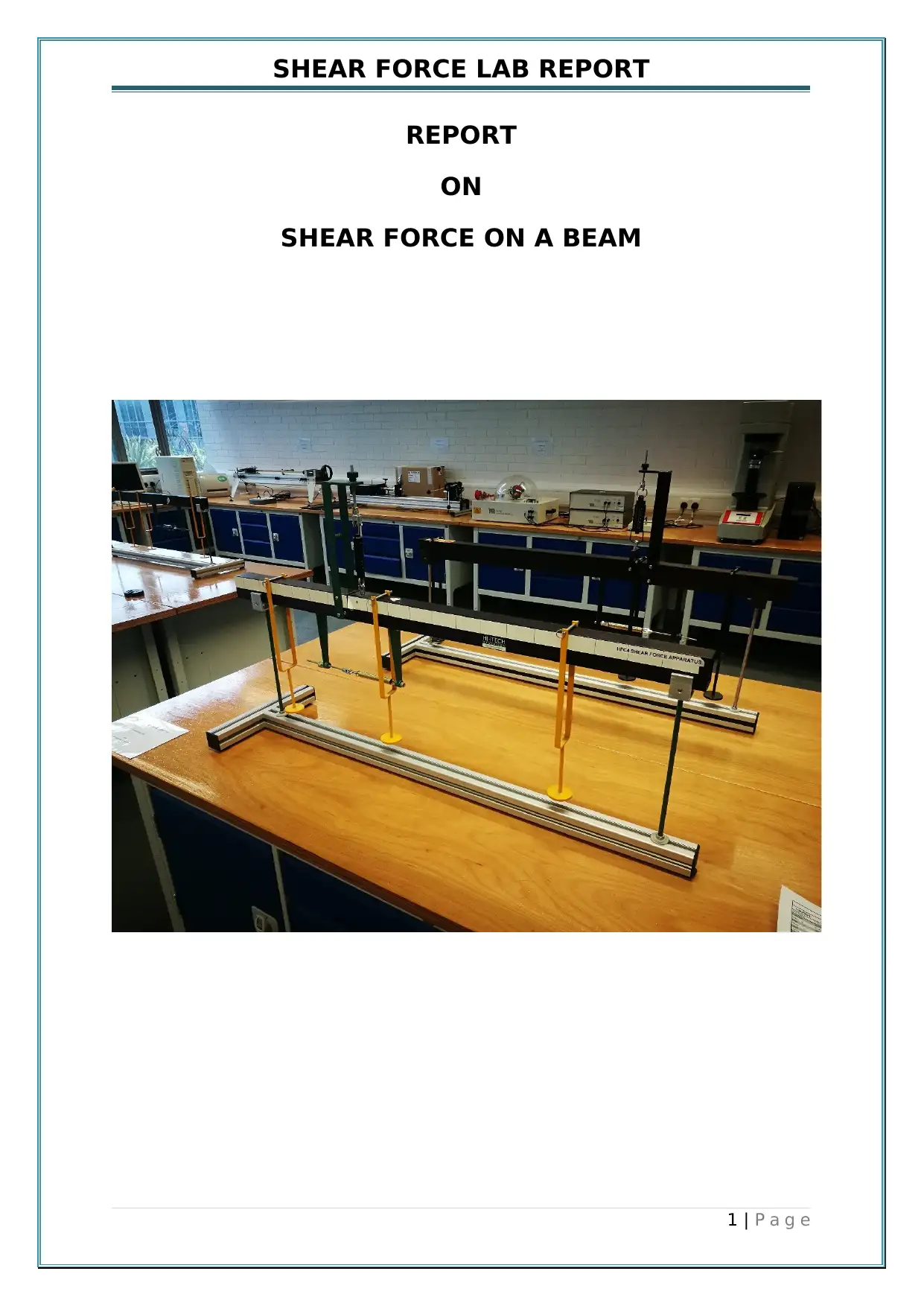
EQUIPMENTS USED
Beam :- On which all the loads and supports are applied and the shear force and
bending moment is obtain.
Weights :- Multiple weights of different values are required to create different
experimental conditions.
Spring balance :-Spring balance is attached at the cut section , initially the at no load
condition the datum value is obtained .
Measuring scale :- To check the reading of length of beam where load is applied.
Weight Hanger :- Weight hanger used to carry the weight , it hangs on beam to
transfer the weight to beam.
4 | P a g e
INTRODUCTION
AIM /OBJECTIVE
The main aim for this experiment is to calculate the shear force at the cut section of beam
using spring balance and multiple weights and compare the obtained experimental value
with the theoretical calculation .
BACKGROUND THEORY
The main theory behind this experiment is when a beam is supported at its ends and force
or load applied on it from the top then a resultant force act on each part of beam along its
length . This resultant force called shear force . Beam also observe bending moment .
Bending moment is product of shear force and displacement along the length of beam.
Units of Bending moment is Nm (Newton meter) and shear force is Newton( Nash , 1998).
EQUIPMENTS USED
Beam :- On which all the loads and supports are applied and the shear force and
bending moment is obtain.
Weights :- Multiple weights of different values are required to create different
experimental conditions.
Spring balance :-Spring balance is attached at the cut section , initially the at no load
condition the datum value is obtained .
Measuring scale :- To check the reading of length of beam where load is applied.
Weight Hanger :- Weight hanger used to carry the weight , it hangs on beam to
transfer the weight to beam.
4 | P a g e
Paraphrase This Document
Need a fresh take? Get an instant paraphrase of this document with our AI Paraphraser

SHEAR FORCE LAB REPORT
EXPERIMENTAL PROCEDURE
Set up all the equipments used as per provided picture and keep the beam straight
enough to get the accurate result.
Initially measure the length of beam from where it is simply supported and length of
cut out section from left side from steel ruler and note it down.
Place the three hanger (carry weight) at different position on the beam and measure
its position from left end of beam .
Due to weight of hangers the beam slightly bend, so use the gauge to straight the
beam and find the datum value of force on beam . This datum value will be
subtracted at the end from the actual experimental value of shear force to get the
exact value.
Now one by one place the weight on the hangers ,then the beam tends to bend.
Both the spring need to be adjusted so that two parts of beam again bring back to
straight condition . Use a straight edge to check the straightness .
Record a force that shown on spring balance after straightening the beam .
Repeat the above steps by changing the location of hangers and weight on hangers .
The result obtain should be checked again to remove human error (Ramsay,2017) .
5 | P a g e

SHEAR FORCE LAB REPORT
RESULT
According to the experimental procedure shown above , there the four cases need to be
tested and all the experimental values obtain are added in table.
Test 1 Test 2 Test 3 Test 4
Distance between both supports 89.5 89.5 89.5 89.5
Spring balance reading with no added
loads (datum)
6.87 6.87 6.87 6.87
Position of load 1 (cm from left support) 7.8 7.8 7.8 7.8
Magnitude of Load 1 (N) 4.92 9.84 9.82 9.82
Position of load 2 (cm from left support) 47.5 47.5 52.3 37.9
Magnitude of Load 2 (N) 4.92 9.82 4.91 9.83
Position of load 3 (cm from left/right side) 75.0 75.0 79.8 70.2
Magnitude of Load 3 (N) 4.91 4.91 9.84 4.92
Spring balance reading with load (N) 9.56 11.77 9.32 13.24
Shear force at cut(sb1-sb2) (N) 2.69 4.9 2.45 6.37
Distance to cut in the beam(cm from left
support)
7.8 7.8 7.8 7.8
6 | P a g e
⊘ This is a preview!⊘
Do you want full access?
Subscribe today to unlock all pages.
Trusted by 1+ million students worldwide
SHEAR FORCE LAB REPORT
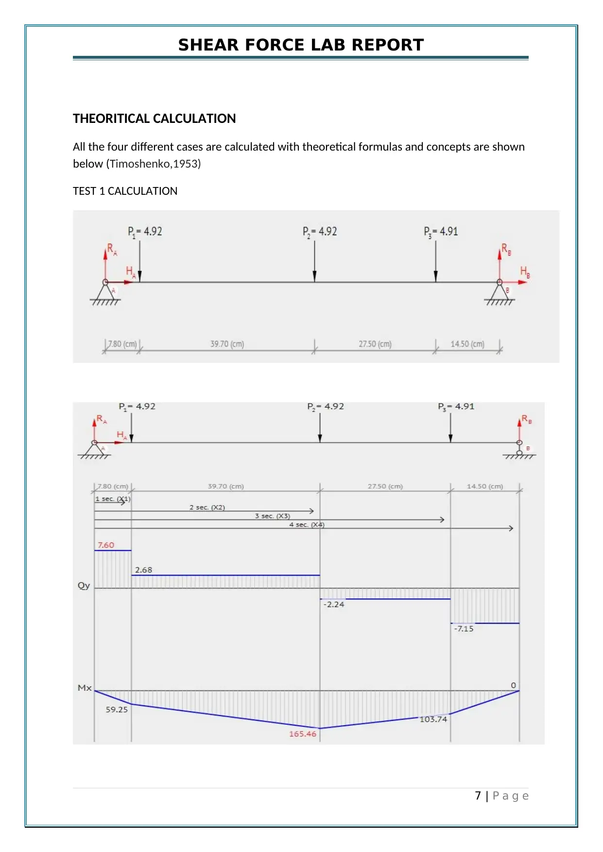
THEORITICAL CALCULATION
All the four different cases are calculated with theoretical formulas and concepts are shown
below (Timoshenko,1953)
TEST 1 CALCULATION
7 | P a g e
THEORITICAL CALCULATION
All the four different cases are calculated with theoretical formulas and concepts are shown
below (Timoshenko,1953)
TEST 1 CALCULATION
7 | P a g e
Paraphrase This Document
Need a fresh take? Get an instant paraphrase of this document with our AI Paraphraser

SHEAR FORCE LAB REPORT
REACTIONS AT A & B (Gere, 1997)
ΣMA = 0: The addition of all moments at point A is equal to zero :
- P1*7.8 - P2*47.5 - P3*75 + RB*89.5 = 0
ΣMB = 0: The addition of all moments at point B is equal to zero:
- RA*89.5 + P1*81.7 + P2*42 + P3*14.5 = 0
2. Now Solve the equations :
Calculate the reaction at roller support at point B :
RB = ( P1*7.8 + P2*47.5 + P3*75) / 89.5 = ( 4.92*7.8 + 4.92*47.5 + 4.91*75) / 89.5 = 7.15 (N)
Calculate the reaction at roller support at point A :
RA = ( P1*81.7 + P2*42 + P3*14.5) / 89.5 = ( 4.92*81.7 + 4.92*42 + 4.91*14.5) / 89.5 = 7.60 (N)
3. The addition of all forces is zero :
ΣFy = 0: RA - P1 - P2 - P3 + RB = 7.60 - 4.92 - 4.92 - 4.91 + 7.15 = 0
SHEAR FORCE & BENDING MOMENT CALCULATION
First span of the beam: 0 ≤ x1 < 7.8
Calculate the shear force at a point (Q):
Q(x1) = + RA
Q1(0) = + 7.60 = 7.60 (N)
Calculate the bending moment at a point (M):
M(x1) = + RA*(x1)
M1(0) = + 7.60*(0) = 0 (N*cm)
M1(7.80) = + 7.60*(7.80) = 59.25 (N*cm)
Second span of the beam: 7.8 ≤ x2 < 47.5
Calculate the shear force at a point (Q):
Q(x2) = + RA - P1
Q2(7.80) = + 7.60 - 4.92 = 2.68 (N)
Q2(47.50) = + 7.60 - 4.92 = 2.68 (N)
Calculate the bending moment at a point (M):
M(x2) = + RA*(x2) - P1*(x2 - 7.8)
M2(7.80) = + 7.60*(7.80) - 4.92*(7.80 - 7.8) = 59.25 (N*cm)
M2(47.50) = + 7.60*(47.50) - 4.92*(47.50 - 7.8) = 165.46 (N*cm)
Third span of the beam: 47.5 ≤ x3 < 75
Calculate the shear force at a point (Q):
Q(x3) = + RA - P1 - P2
Q3(47.50) = + 7.60 - 4.92 - 4.92 = -2.24 (N)
Q3(75) = + 7.60 - 4.92 - 4.92 = -2.24 (N)
Calculate the bending moment at a point (M):
M(x3) = + RA*(x3) - P1*(x3 - 7.8) - P2*(x3 - 47.5)
8 | P a g e

SHEAR FORCE LAB REPORT
M3(47.50) = + 7.60*(47.50) - 4.92*(47.50 - 7.8) - 4.92*(47.50 - 47.5) = 165.46 (N*cm)
M3(75) = + 7.60*(75) - 4.92*(75 - 7.8) - 4.92*(75 - 47.5) = 103.74 (N*cm)
Fourth span of the beam: 75 ≤ x4 < 89.5
Calculate the shear force at a point (Q):
Q(x4) = + RA - P1 - P2 - P3
Q4(75) = + 7.60 - 4.92 - 4.92 - 4.91 = -7.15 (N)
Q4(89.50) = + 7.60 - 4.92 - 4.92 - 4.91 = -7.15 (N)
Calculate the bending moment at a point (M):
M(x4) = + RA*(x4) - P1*(x4 - 7.8) - P2*(x4 - 47.5) - P3*(x4 - 75)
M4(75) = + 7.60*(75) - 4.92*(75 - 7.8) - 4.92*(75 - 47.5) - 4.91*(75 - 75) = 103.74 (N*cm)
M4(89.50) = + 7.60*(89.50) - 4.92*(89.50 - 7.8) - 4.92*(89.50 - 47.5) - 4.91*(89.50 - 75) = 0
(N*cm)
TEST 2 CALCULATION
9 | P a g e
⊘ This is a preview!⊘
Do you want full access?
Subscribe today to unlock all pages.
Trusted by 1+ million students worldwide

SHEAR FORCE LAB REPORT
REACTIONS AT A & B
ΣMA = 0: The addition of all moments at point A is equal to zero:
- P1*7.8 - P2*47.5 - P3*75 + RB*89.5 = 0
ΣMB = 0: The addition of all moments at point B is equal to zero:
- RA*89.5 + P1*81.7 + P2*42 + P3*14.5 = 0
2. Solve this equations:
Calculate the reaction at roller support at point B:
RB = ( P1*7.8 + P2*47.5 + P3*75) / 89.5 = ( 9.84*7.8 + 9.82*47.5 + 4.91*75) / 89.5 = 10.18 (N)
Calculate the reaction at roller support at point A:
RA = ( P1*81.7 + P2*42 + P3*14.5) / 89.5 = ( 9.84*81.7 + 9.82*42 + 4.91*14.5) / 89.5 = 14.39 (N)
3.The addition of all forces is zero: ΣFy = 0: RA - P1 - P2 - P3 + RB = 14.39 - 9.84 - 9.82 - 4.91 +
10.18 = 0
SHEAR FORCE & BENDING MOMENT CALCULATION
First span of the beam: 0 ≤ x1 < 7.8
Calculate the shear force at a point (Q):
Q(x1) = + RA
Q1(0) = + 14.39 = 14.39 (N)
10 | P a g e
Paraphrase This Document
Need a fresh take? Get an instant paraphrase of this document with our AI Paraphraser

SHEAR FORCE LAB REPORT
Calculate the bending moment at a point (M):
M(x1) = + RA*(x1)
M1(0) = + 14.39*(0) = 0 (N*cm)
M1(7.80) = + 14.39*(7.80) = 112.21 (N*cm)
Second span of the beam: 7.8 ≤ x2 < 47.5
Calculate the shear force at a point (Q):
Q(x2) = + RA - P1
Q2(7.80) = + 14.39 - 9.84 = 4.55 (N)
Q2(47.50) = + 14.39 - 9.84 = 4.55 (N)
Calculate the bending moment at a point (M):
M(x2) = + RA*(x2) - P1*(x2 - 7.8)
M2(7.80) = + 14.39*(7.80) - 9.84*(7.80 - 7.8) = 112.21 (N*cm)
M2(47.50) = + 14.39*(47.50) - 9.84*(47.50 - 7.8) = 292.70 (N*cm)
Third span of the beam: 47.5 ≤ x3 < 75
Calculate the shear force at a point (Q):
Q(x3) = + RA - P1 - P2
Q3(47.50) = + 14.39 - 9.84 - 9.82 = -5.27 (N)
Q3(75) = + 14.39 - 9.84 - 9.82 = -5.27 (N)
Calculate the bending moment at a point (M):
M(x3) = + RA*(x3) - P1*(x3 - 7.8) - P2*(x3 - 47.5)
M3(47.50) = + 14.39*(47.50) - 9.84*(47.50 - 7.8) - 9.82*(47.50 - 47.5) = 292.70 (N*cm)
M3(75) = + 14.39*(75) - 9.84*(75 - 7.8) - 9.82*(75 - 47.5) = 147.67 (N*cm)
Fourth span of the beam: 75 ≤ x4 < 89.5
Calculate the shear force at a point (Q):
Q(x4) = + RA - P1 - P2 - P3
Q4(75) = + 14.39 - 9.84 - 9.82 - 4.91 = -10.18 (N)
Q4(89.50) = + 14.39 - 9.84 - 9.82 - 4.91 = -10.18 (N)
Calculate the bending moment at a point (M):
M(x4) = + RA*(x4) - P1*(x4 - 7.8) - P2*(x4 - 47.5) - P3*(x4 - 75)
11 | P a g e
Calculate the bending moment at a point (M):
M(x1) = + RA*(x1)
M1(0) = + 14.39*(0) = 0 (N*cm)
M1(7.80) = + 14.39*(7.80) = 112.21 (N*cm)
Second span of the beam: 7.8 ≤ x2 < 47.5
Calculate the shear force at a point (Q):
Q(x2) = + RA - P1
Q2(7.80) = + 14.39 - 9.84 = 4.55 (N)
Q2(47.50) = + 14.39 - 9.84 = 4.55 (N)
Calculate the bending moment at a point (M):
M(x2) = + RA*(x2) - P1*(x2 - 7.8)
M2(7.80) = + 14.39*(7.80) - 9.84*(7.80 - 7.8) = 112.21 (N*cm)
M2(47.50) = + 14.39*(47.50) - 9.84*(47.50 - 7.8) = 292.70 (N*cm)
Third span of the beam: 47.5 ≤ x3 < 75
Calculate the shear force at a point (Q):
Q(x3) = + RA - P1 - P2
Q3(47.50) = + 14.39 - 9.84 - 9.82 = -5.27 (N)
Q3(75) = + 14.39 - 9.84 - 9.82 = -5.27 (N)
Calculate the bending moment at a point (M):
M(x3) = + RA*(x3) - P1*(x3 - 7.8) - P2*(x3 - 47.5)
M3(47.50) = + 14.39*(47.50) - 9.84*(47.50 - 7.8) - 9.82*(47.50 - 47.5) = 292.70 (N*cm)
M3(75) = + 14.39*(75) - 9.84*(75 - 7.8) - 9.82*(75 - 47.5) = 147.67 (N*cm)
Fourth span of the beam: 75 ≤ x4 < 89.5
Calculate the shear force at a point (Q):
Q(x4) = + RA - P1 - P2 - P3
Q4(75) = + 14.39 - 9.84 - 9.82 - 4.91 = -10.18 (N)
Q4(89.50) = + 14.39 - 9.84 - 9.82 - 4.91 = -10.18 (N)
Calculate the bending moment at a point (M):
M(x4) = + RA*(x4) - P1*(x4 - 7.8) - P2*(x4 - 47.5) - P3*(x4 - 75)
11 | P a g e
SHEAR FORCE LAB REPORT
M4(75) = + 14.39*(75) - 9.84*(75 - 7.8) - 9.82*(75 - 47.5) - 4.91*(75 - 75) = 147.67 (N*cm)
M4(89.50) = + 14.39*(89.50) - 9.84*(89.50 - 7.8) - 9.82*(89.50 - 47.5) - 4.91*(89.50 - 75) = 0
(N*cm)
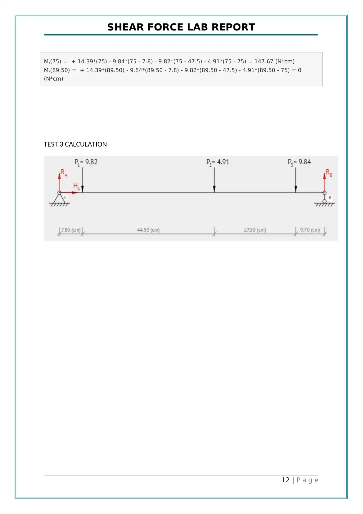
TEST 3 CALCULATION
12 | P a g e
M4(75) = + 14.39*(75) - 9.84*(75 - 7.8) - 9.82*(75 - 47.5) - 4.91*(75 - 75) = 147.67 (N*cm)
M4(89.50) = + 14.39*(89.50) - 9.84*(89.50 - 7.8) - 9.82*(89.50 - 47.5) - 4.91*(89.50 - 75) = 0
(N*cm)
TEST 3 CALCULATION
12 | P a g e
⊘ This is a preview!⊘
Do you want full access?
Subscribe today to unlock all pages.
Trusted by 1+ million students worldwide
1 out of 20


Your All-in-One AI-Powered Toolkit for Academic Success.
+13062052269
info@desklib.com
Available 24*7 on WhatsApp / Email
![[object Object]](/_next/static/media/star-bottom.7253800d.svg)
Unlock your academic potential
Copyright © 2020–2026 A2Z Services. All Rights Reserved. Developed and managed by ZUCOL.