55-500314 Applied Thermofluids: Shell and Tube Heat Exchanger Analysis
VerifiedAdded on 2022/08/13
|22
|3493
|17
Report
AI Summary
This report delves into the thermal design and analysis of shell and tube heat exchangers, a critical component in numerous engineering applications. It begins with an introduction to heat exchangers, including their classification based on flow arrangements and construction, with a focus on tubular heat exchangers and, specifically, shell and tube heat exchangers (STHEs). The report details the design and analysis of STHEs, covering rating and sizing methodologies, along with the governing equations for heat transfer. It discusses the calculation of the overall heat transfer coefficient (UA) and the determination of the log mean temperature difference (LMTD) and the effectiveness-NTU method for heat transfer analysis. The report also includes worked examples and a critique of the concepts presented, providing a comprehensive overview of STHE design and analysis.

Shell and Tube Heat exchanger
Thermal Design and Analysis
Thermal Design and Analysis
Paraphrase This Document
Need a fresh take? Get an instant paraphrase of this document with our AI Paraphraser
Contents
1. Introduction 3
2. Classification of Heat Exchangers 3
3. Shell and Tube Heat Exchanger 6
4. Design and Analysis of Heat Exchanger 8
5. Worked Examples 16
6. Critique 20
References 21
Page | 2
1. Introduction 3
2. Classification of Heat Exchangers 3
3. Shell and Tube Heat Exchanger 6
4. Design and Analysis of Heat Exchanger 8
5. Worked Examples 16
6. Critique 20
References 21
Page | 2
1. Introduction
Exchange of heat between two or more fluids at different temperatures is a prominent
process used in various engineering applications. The thermodynamic device used for this
purpose is called Heat Exchanger. The basic properties of heat conduction govern the process
of heat transfer through fluid-to-fluid heat exchangers. When two independent spaces or
circuits carrying fluids with a temperature difference come in contact, the heat always moves
to cold, trying to find equilibrium. The fluids could be either in direct contact or indirect. The
various applications of heat exchangers include HVAC applications, automotive,
chemical/petrochemical, power generations, heat recovery and naval applications (Incropera,,
Dewitt,, Bergman, & Lavine, 2007).
2. Classification of Heat Exchangers
Heat Exchangers(HEX) can be classified by various methods. A comprehensive list of
the classification of HEX can be found in (Kakac,, Liu, & Pramuanjaroenkij, 2012), (Zohuri,
2017). The more frequently utilised type of HEX are classified on the basis of a) flow
arrangements and b) construction.
Classification based on flow arrangements:
The various types of HEX under this category are:
1. Parallel Flow or Co-current flow
2. Counter Flow
3. Hybrids such as Multi pass flow and Cross Counterflow
4. Crossflow
Page | 3
⊘ This is a preview!⊘
Do you want full access?
Subscribe today to unlock all pages.

Trusted by 1+ million students worldwide
5.
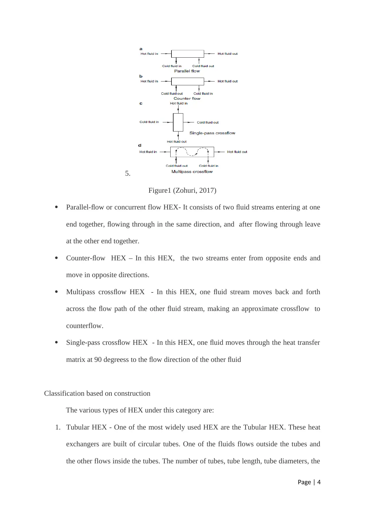
Figure1 (Zohuri, 2017)
Parallel-flow or concurrent flow HEX- It consists of two fluid streams entering at one
end together, flowing through in the same direction, and after flowing through leave
at the other end together.
Counter-flow HEX – In this HEX, the two streams enter from opposite ends and
move in opposite directions.
Multipass crossflow HEX - In this HEX, one fluid stream moves back and forth
across the flow path of the other fluid stream, making an approximate crossflow to
counterflow.
Single-pass crossflow HEX - In this HEX, one fluid moves through the heat transfer
matrix at 90 degreess to the flow direction of the other fluid
Classification based on construction
The various types of HEX under this category are:
1. Tubular HEX - One of the most widely used HEX are the Tubular HEX. These heat
exchangers are built of circular tubes. One of the fluids flows outside the tubes and
the other flows inside the tubes. The number of tubes, tube length, tube diameters, the
Page | 4
Paraphrase This Document
Need a fresh take? Get an instant paraphrase of this document with our AI Paraphraser
pitch of tubes and the arrangement of tubes can be changed. They can be
manufactured relatively easily and have relatively low cost. Thus wide range of
design, ease of manufacturing and low cost are primary reasons for their widespread
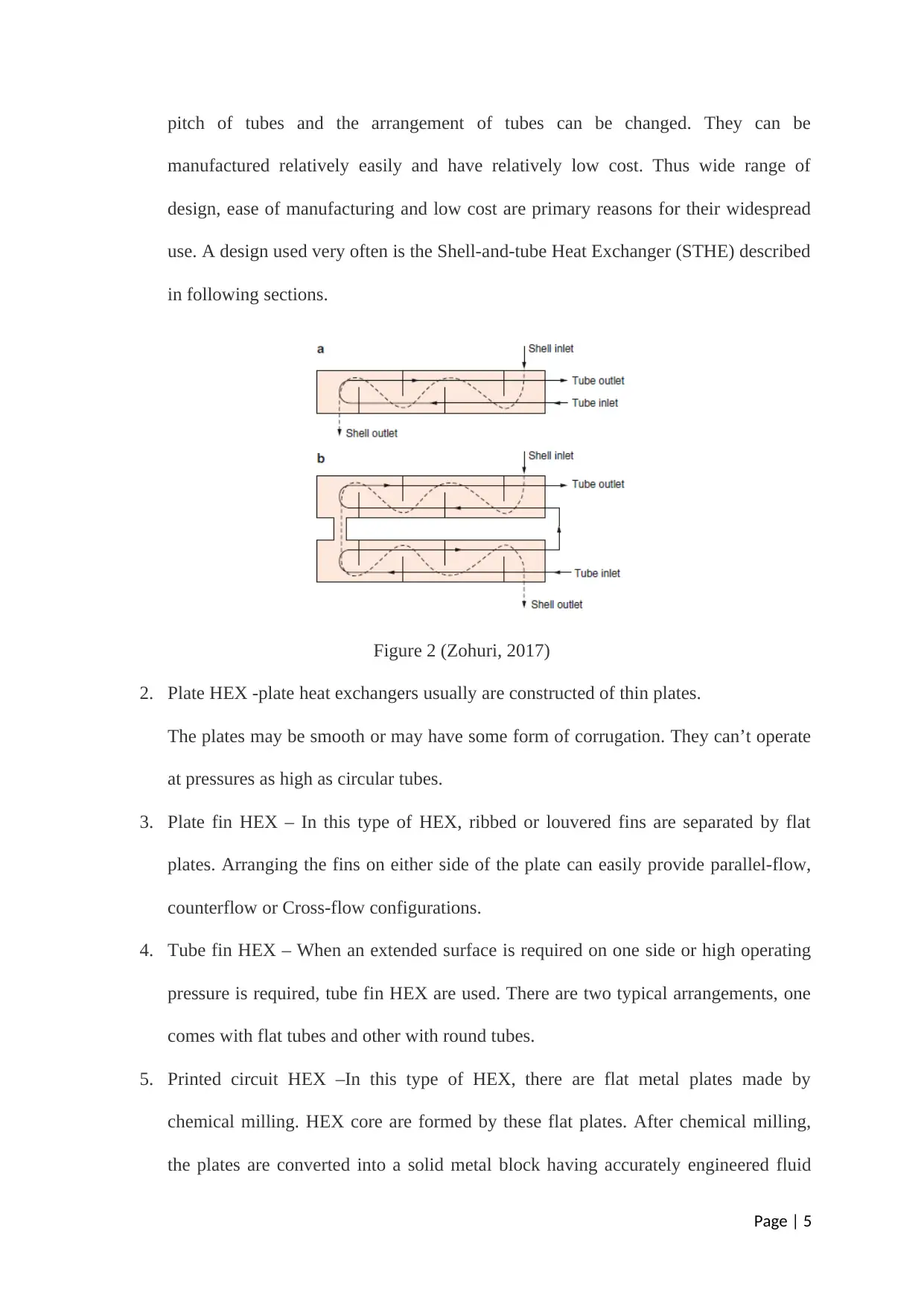
use. A design used very often is the Shell-and-tube Heat Exchanger (STHE) described
in following sections.
Figure 2 (Zohuri, 2017)
2. Plate HEX -plate heat exchangers usually are constructed of thin plates.
The plates may be smooth or may have some form of corrugation. They can’t operate
at pressures as high as circular tubes.
3. Plate fin HEX – In this type of HEX, ribbed or louvered fins are separated by flat
plates. Arranging the fins on either side of the plate can easily provide parallel-flow,
counterflow or Cross-flow configurations.
4. Tube fin HEX – When an extended surface is required on one side or high operating
pressure is required, tube fin HEX are used. There are two typical arrangements, one
comes with flat tubes and other with round tubes.
5. Printed circuit HEX –In this type of HEX, there are flat metal plates made by
chemical milling. HEX core are formed by these flat plates. After chemical milling,
the plates are converted into a solid metal block having accurately engineered fluid
Page | 5
flow passages. The conversion into solid metal block is done by stacking and
diffusion bonding.
6. Regenerative HEX - In this type of HEX, heating of heat transfer matrix is done by
one fluid and then second fluid cools it. Both the fluids flow over the same surfaces of
the matrix and this flow is switched with passage of time.
3. Shell and tube Heat Exchanger (STHE)
The following sections will discuss and describe analysis of Shell-and-tube Heat
Exchanger (STHE). STHE are one of the most widely used heat exchangers due to the
flexibility in their design and ease of manufacturing. It comes under the category of Tubular
HEX. As mentioned earlier, one of the fluids flows outside the tubes and the other flows
inside the tubes. The heat transfer occurs from the hot fluid to the cold fluid. The temperature
of the hot fluid lowers while leaving the STHE and temperature of the cold fluid increases
while leaving the STHE. Shell and tube heat exchangers can be categorised into two main
types(Brogan, 2011). These are following:
a)First ones are covered by standards from TEMA which is Tubular Exchanger
Manufacturers Association (TEMA, 1988)and are used in the petrochemical industry.
b) Second ones include power plant condensers and feedwater heaters and others which are
mainly utilized in power industry.
The shell and tube exchanger consists of the following four major parts(Brogan, 2011):
a) Tube bundle(tubes)—It consists of the tube sheets, baffles, tubes and tie rods etc. to hold
the bundle together.
b) Shell—Tube bundles are contained in shell.
c) Front Header — It’s the part of the HEX from where the fluid enters the tubeside.
Page | 6
⊘ This is a preview!⊘
Do you want full access?
Subscribe today to unlock all pages.

Trusted by 1+ million students worldwide
d) Rear Header— The part of the HEX from where the tubeside fluid leaves is the rear
header. In multiple tubeside passes, the fluid is returned to the front header.
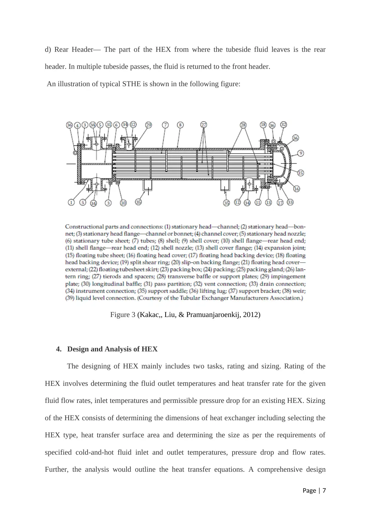
An illustration of typical STHE is shown in the following figure:
Figure 3 (Kakac,, Liu, & Pramuanjaroenkij, 2012)
4. Design and Analysis of HEX
The designing of HEX mainly includes two tasks, rating and sizing. Rating of the
HEX involves determining the fluid outlet temperatures and heat transfer rate for the given
fluid flow rates, inlet temperatures and permissible pressure drop for an existing HEX. Sizing
of the HEX consists of determining the dimensions of heat exchanger including selecting the
HEX type, heat transfer surface area and determining the size as per the requirements of
specified cold-and-hot fluid inlet and outlet temperatures, pressure drop and flow rates.
Further, the analysis would outline the heat transfer equations. A comprehensive design
Page | 7
Paraphrase This Document
Need a fresh take? Get an instant paraphrase of this document with our AI Paraphraser
analysis would however involve structural, manufacturing and economical aspects apart from
the thermal considerations presented in the current work.
Apart from sizing and rating, two other tasks from operating the HEX are finding the
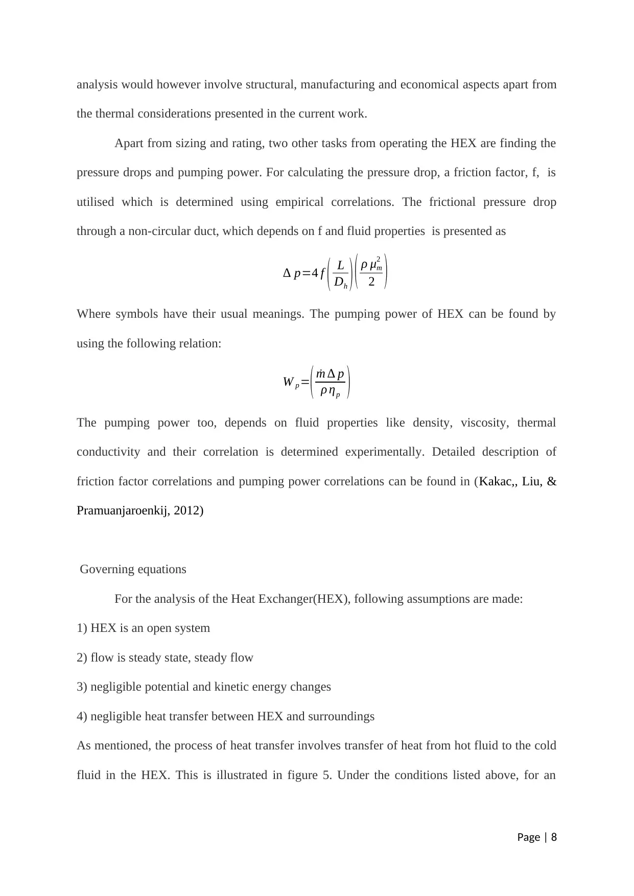
pressure drops and pumping power. For calculating the pressure drop, a friction factor, f, is
utilised which is determined using empirical correlations. The frictional pressure drop
through a non-circular duct, which depends on f and fluid properties is presented as
∆ p=4 f ( L
Dh ) ( ρ μm
2
2 )
Where symbols have their usual meanings. The pumping power of HEX can be found by
using the following relation:
W p =
( ˙m ∆ p
ρ ηp )
The pumping power too, depends on fluid properties like density, viscosity, thermal
conductivity and their correlation is determined experimentally. Detailed description of
friction factor correlations and pumping power correlations can be found in (Kakac,, Liu, &
Pramuanjaroenkij, 2012)
Governing equations
For the analysis of the Heat Exchanger(HEX), following assumptions are made:
1) HEX is an open system
2) flow is steady state, steady flow
3) negligible potential and kinetic energy changes
4) negligible heat transfer between HEX and surroundings
As mentioned, the process of heat transfer involves transfer of heat from hot fluid to the cold
fluid in the HEX. This is illustrated in figure 5. Under the conditions listed above, for an
Page | 8
infinitesimal change of state of a fluid, the heat transfer rate from First Law of
Thermodynamics is given by
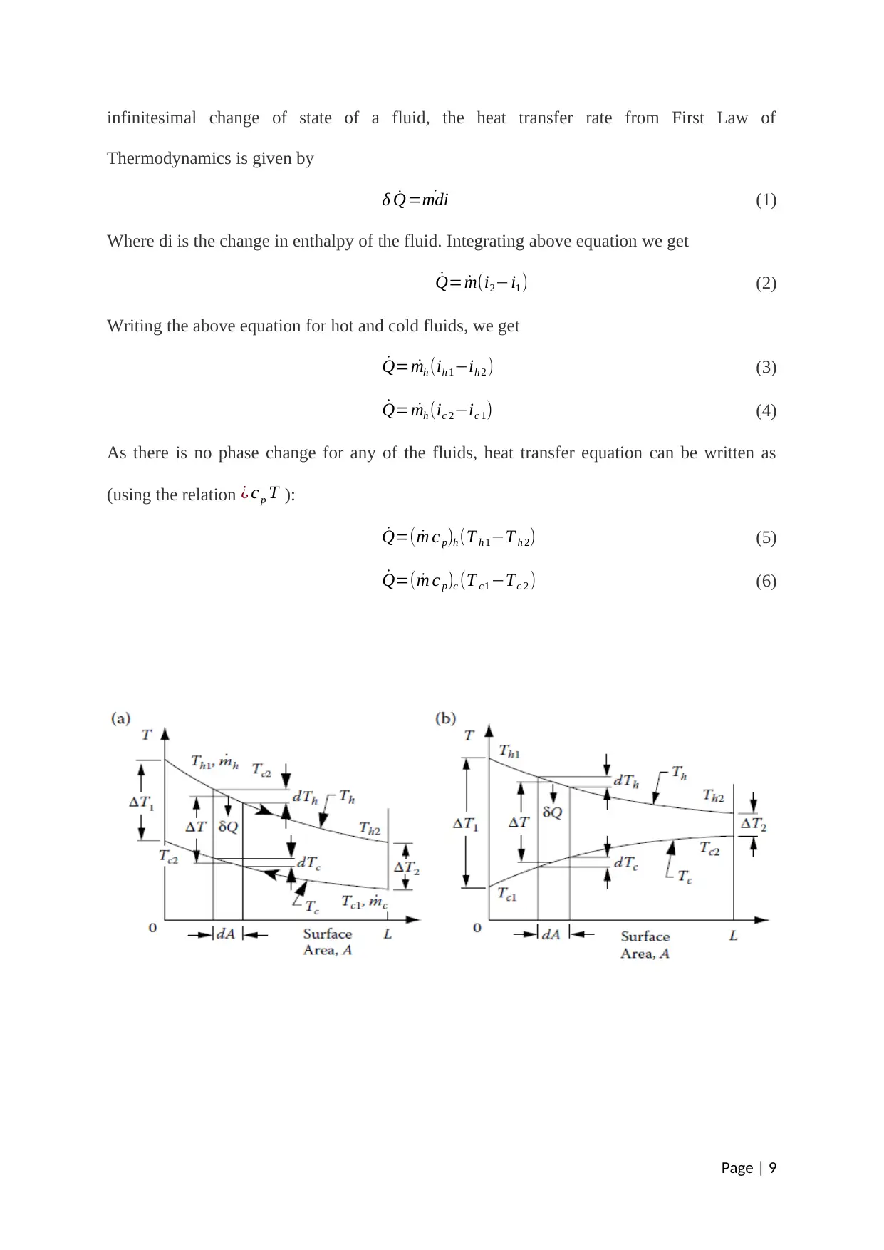
δ ˙Q= ˙mdi (1)
Where di is the change in enthalpy of the fluid. Integrating above equation we get
˙Q= ˙m(i2−i1 ) (2)
Writing the above equation for hot and cold fluids, we get
˙Q= ˙mh (ih 1−ih 2 ) (3)
˙Q= ˙mh (ic 2−ic 1) (4)
As there is no phase change for any of the fluids, heat transfer equation can be written as
(using the relation ¿ c p T ):
˙Q=( ˙m c p)h (T h 1−T h 2) (5)
˙Q=( ˙m c p)c (T c1 −Tc 2 ) (6)
Page | 9
⊘ This is a preview!⊘
Do you want full access?
Subscribe today to unlock all pages.

Trusted by 1+ million students worldwide
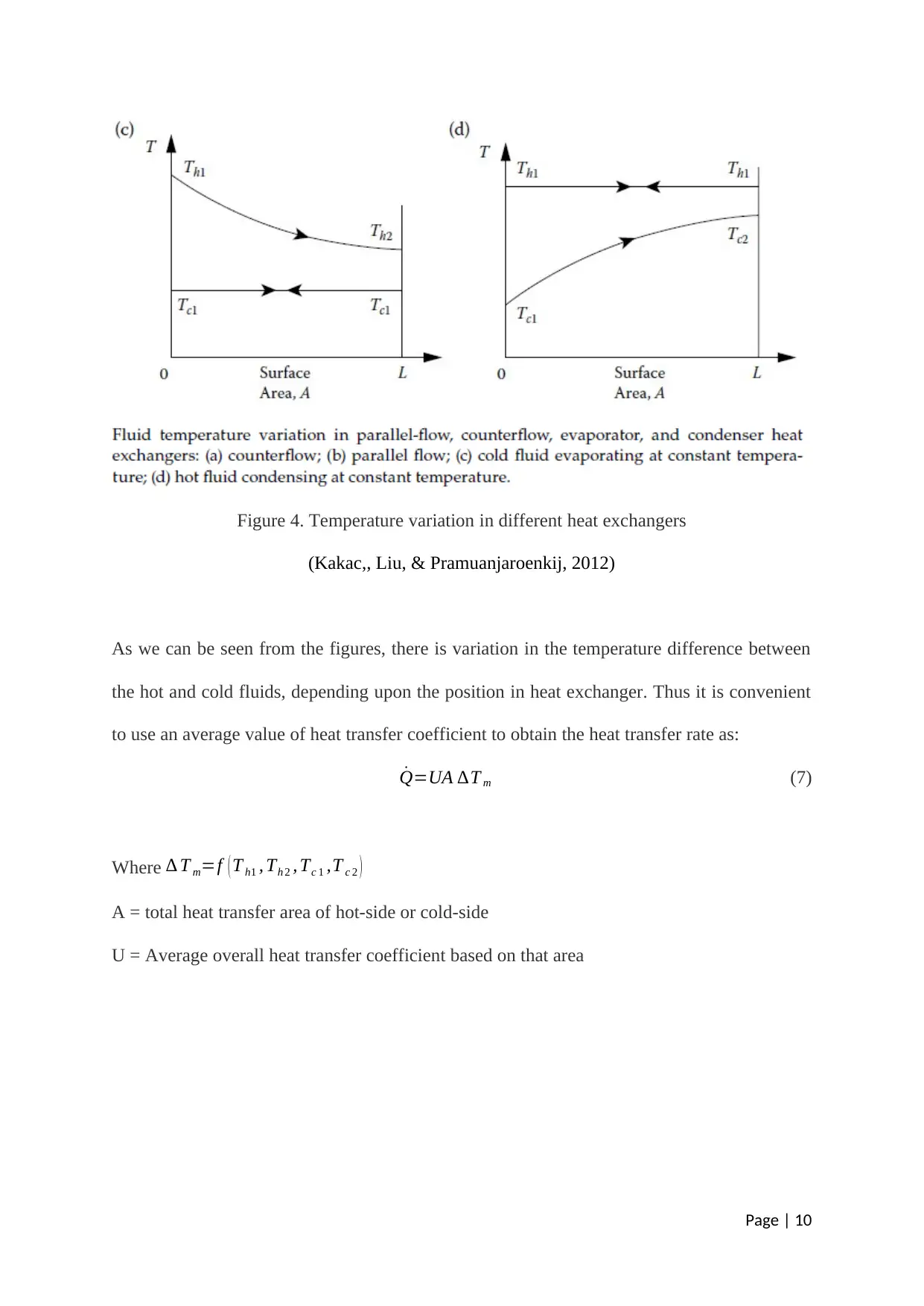
Figure 4. Temperature variation in different heat exchangers
(Kakac,, Liu, & Pramuanjaroenkij, 2012)
As we can be seen from the figures, there is variation in the temperature difference between
the hot and cold fluids, depending upon the position in heat exchanger. Thus it is convenient
to use an average value of heat transfer coefficient to obtain the heat transfer rate as:
˙Q=UA ∆T m (7)
Where ∆ T m=f ( T h1 , Th 2 , Tc 1 ,T c 2 )
A = total heat transfer area of hot-side or cold-side
U = Average overall heat transfer coefficient based on that area
Page | 10
Paraphrase This Document
Need a fresh take? Get an instant paraphrase of this document with our AI Paraphraser
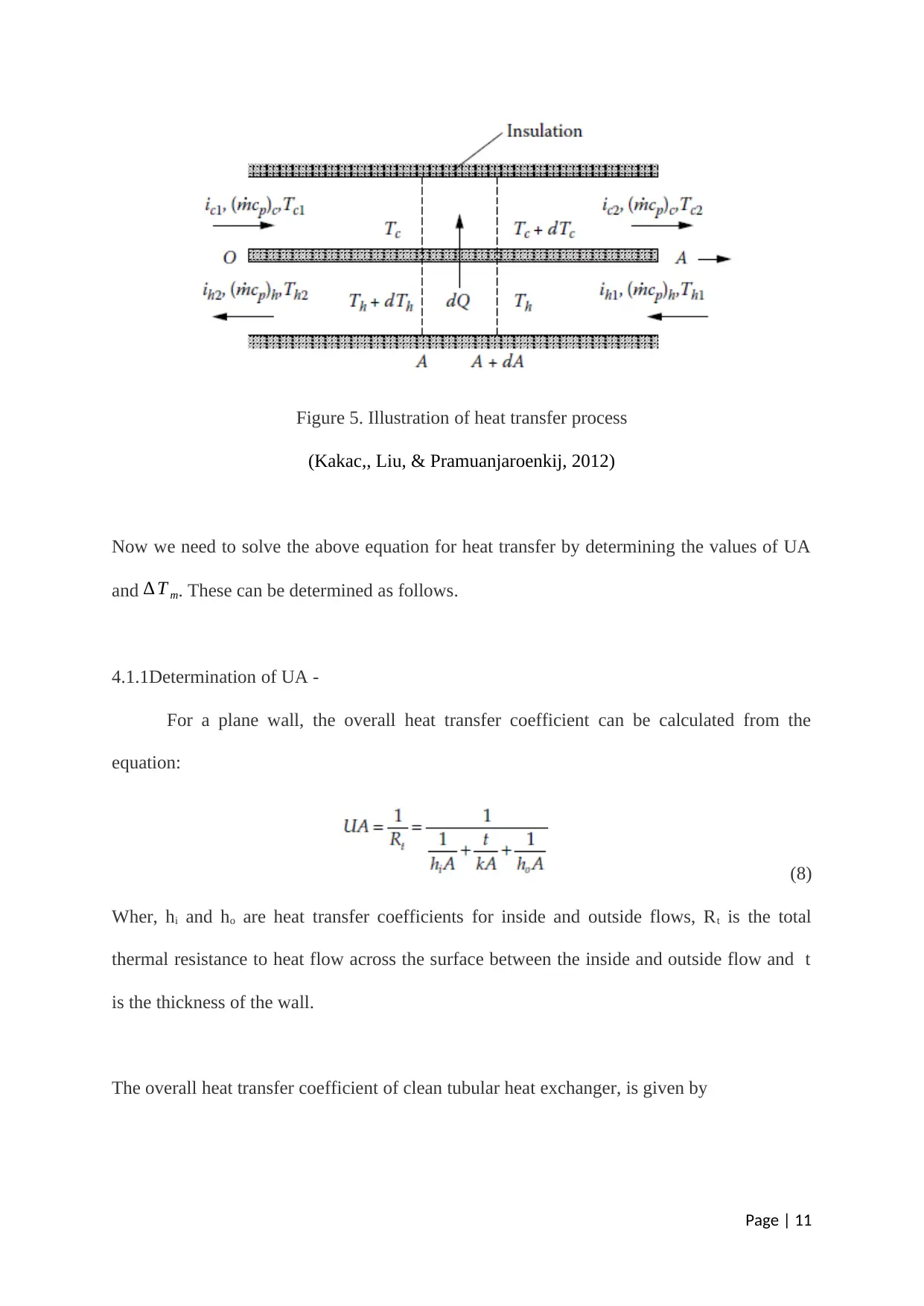
Figure 5. Illustration of heat transfer process
(Kakac,, Liu, & Pramuanjaroenkij, 2012)
Now we need to solve the above equation for heat transfer by determining the values of UA
and ∆ T m. These can be determined as follows.
4.1.1Determination of UA -
For a plane wall, the overall heat transfer coefficient can be calculated from the
equation:
(8)
Wher, hi and ho are heat transfer coefficients for inside and outside flows, Rt is the total
thermal resistance to heat flow across the surface between the inside and outside flow and t
is the thickness of the wall.
The overall heat transfer coefficient of clean tubular heat exchanger, is given by
Page | 11
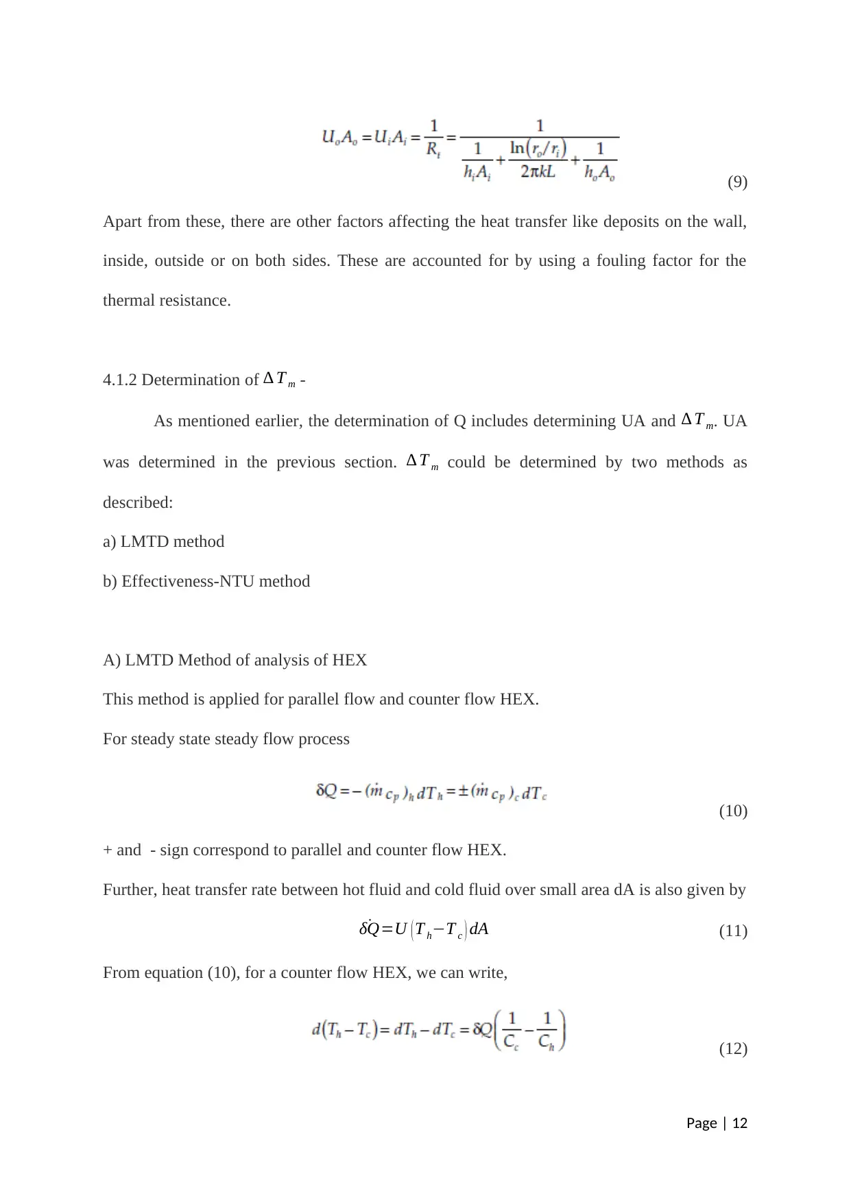
(9)
Apart from these, there are other factors affecting the heat transfer like deposits on the wall,
inside, outside or on both sides. These are accounted for by using a fouling factor for the
thermal resistance.
4.1.2 Determination of ∆ T m -
As mentioned earlier, the determination of Q includes determining UA and ∆ T m. UA
was determined in the previous section. ∆ T m could be determined by two methods as
described:
a) LMTD method
b) Effectiveness-NTU method
A) LMTD Method of analysis of HEX
This method is applied for parallel flow and counter flow HEX.
For steady state steady flow process
(10)
+ and - sign correspond to parallel and counter flow HEX.
Further, heat transfer rate between hot fluid and cold fluid over small area dA is also given by
˙δQ=U ( T h−T c ) dA (11)
From equation (10), for a counter flow HEX, we can write,
(12)
Page | 12
⊘ This is a preview!⊘
Do you want full access?
Subscribe today to unlock all pages.

Trusted by 1+ million students worldwide
1 out of 22
Related Documents
Your All-in-One AI-Powered Toolkit for Academic Success.
+13062052269
info@desklib.com
Available 24*7 on WhatsApp / Email
![[object Object]](/_next/static/media/star-bottom.7253800d.svg)
Unlock your academic potential
Copyright © 2020–2026 A2Z Services. All Rights Reserved. Developed and managed by ZUCOL.


