Shell and Tube Heat Exchanger Design, Analysis, and Optimization

Verified

Added on  2023/01/20

|12
|1633
|36
Project
AI Summary
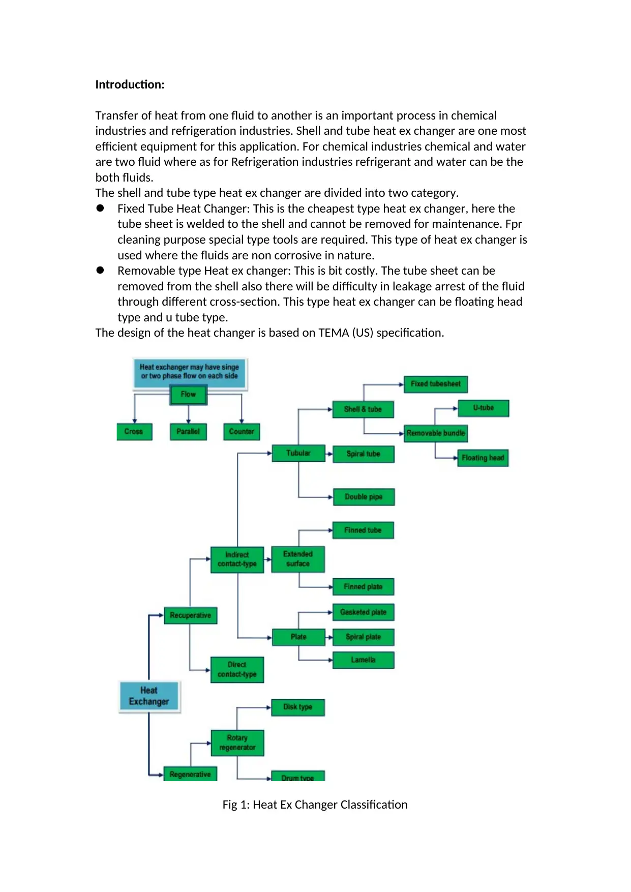
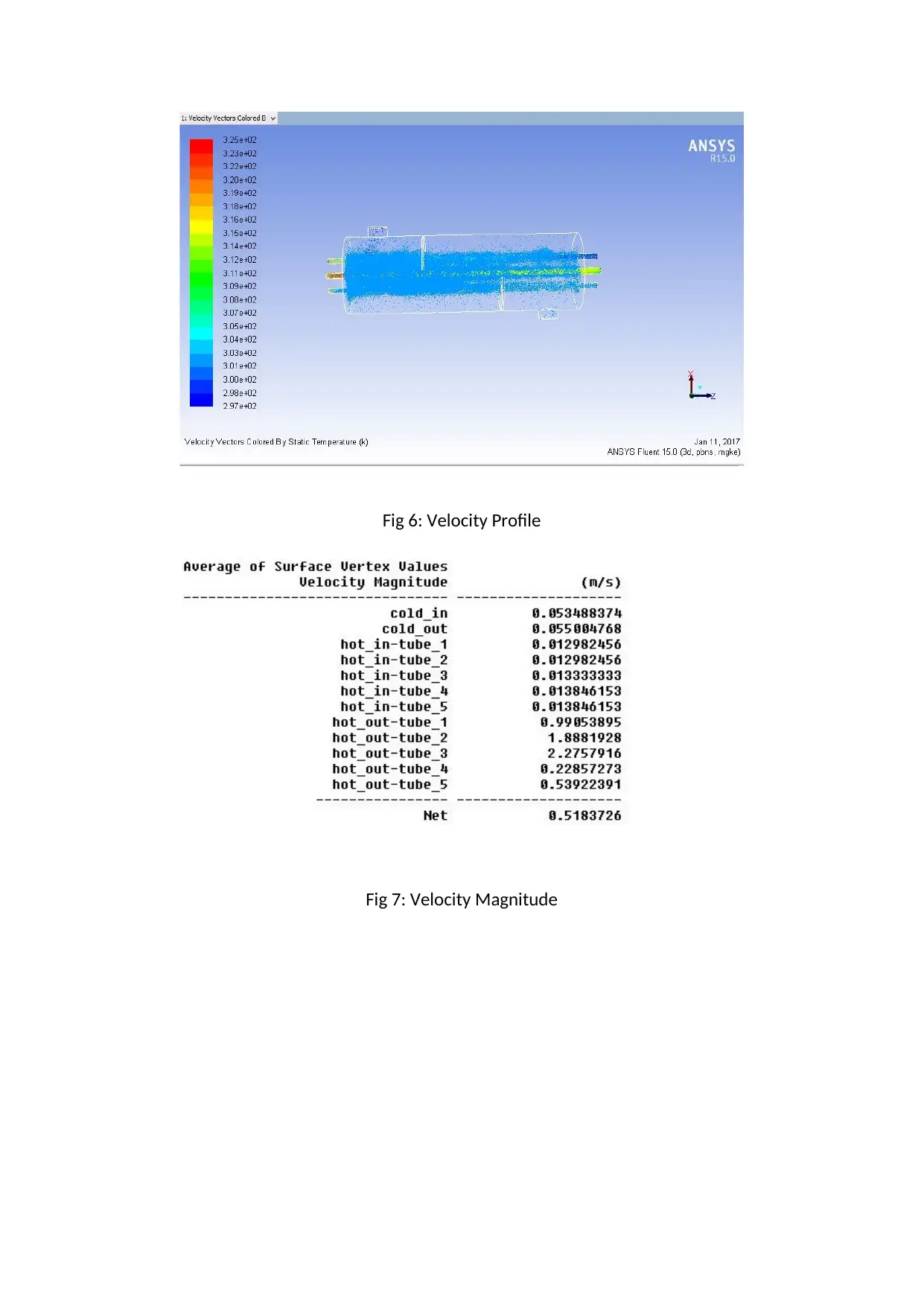
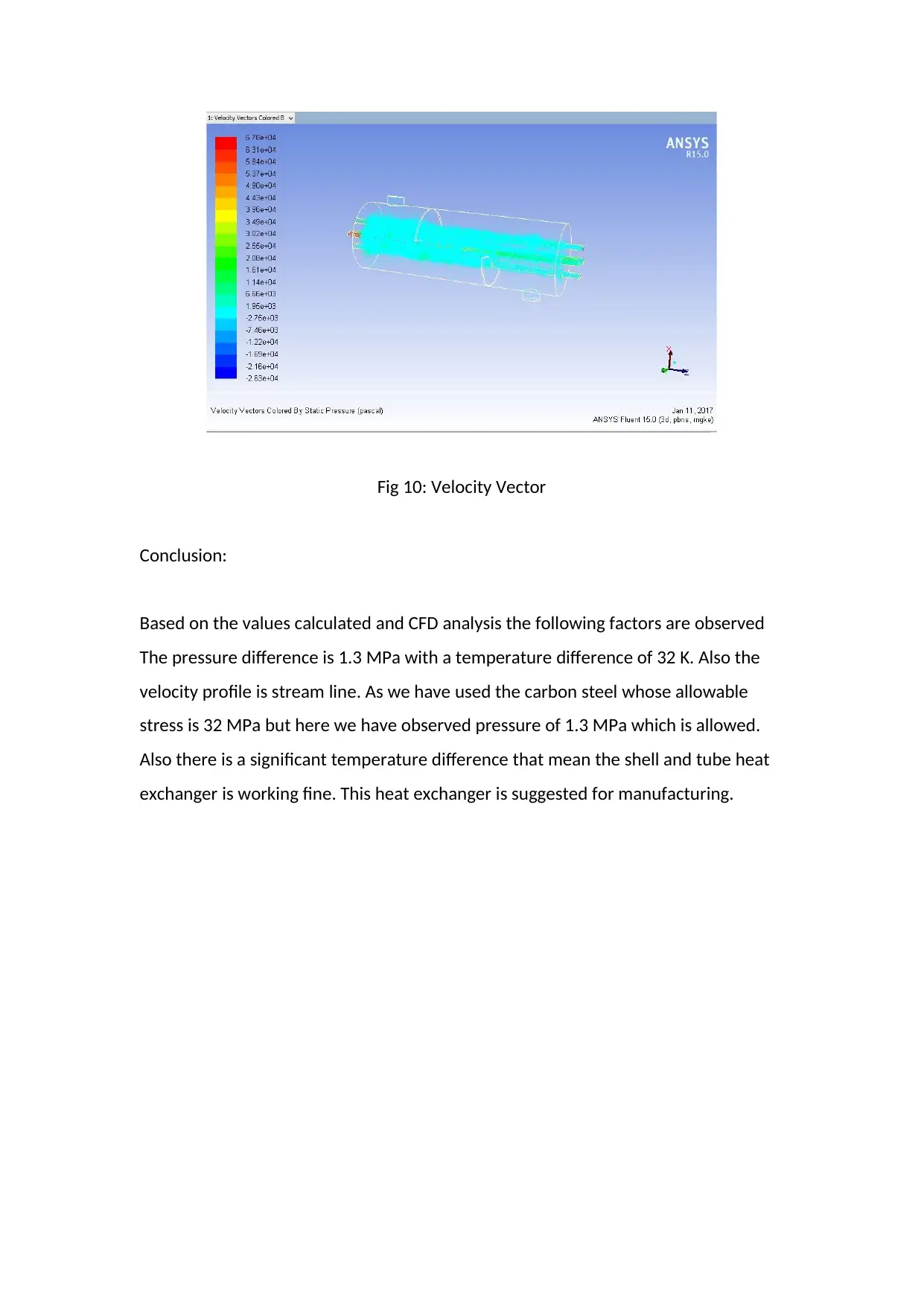
This project focuses on the design and analysis of a shell and tube heat exchanger, a crucial component in chemical and refrigeration industries. The project begins with an introduction to different types of heat exchangers, including fixed tube and removable types, and their applications. It then delves into the design considerations, encompassing thermal aspects like heat transfer area, tube dimensions, and baffle design, as well as shell design and tube layout. Detailed calculations are presented, covering heat transfer coefficients, Reynolds numbers, and the log mean temperature difference. The project also describes experimental calculations and the use of CFD analysis to simulate and validate the heat exchanger's performance. The results, including velocity, temperature, and pressure profiles, are analyzed to assess the exchanger's efficiency and structural integrity. The conclusion confirms the heat exchanger's suitability for manufacturing based on the calculated values and CFD analysis.
tabler-icon-diamond-filled.svg

Contribute Materials

Your contribution can guide someone’s learning journey. Share your documents today.
Document Page
Introduction:
Transfer of heat from one fluid to another is an important process in chemical
industries and refrigeration industries. Shell and tube heat ex changer are one most
efficient equipment for this application. For chemical industries chemical and water
are two fluid where as for Refrigeration industries refrigerant and water can be the
both fluids.
The shell and tube type heat ex changer are divided into two category.
Fixed Tube Heat Changer: This is the cheapest type heat ex changer, here the
tube sheet is welded to the shell and cannot be removed for maintenance. Fpr
cleaning purpose special type tools are required. This type of heat ex changer is
used where the fluids are non corrosive in nature.
Removable type Heat ex changer: This is bit costly. The tube sheet can be
removed from the shell also there will be difficulty in leakage arrest of the fluid
through different cross-section. This type heat ex changer can be floating head
type and u tube type.
The design of the heat changer is based on TEMA (US) specification.
Fig 1: Heat Ex Changer Classification
tabler-icon-diamond-filled.svg

Secure Best Marks with AI Grader

Need help grading? Try our AI Grader for instant feedback on your assignments.
Document Page
Heat Changer Nomenclature:
Fig 2: Heat ex changer Nomenclature
Design Consideration:
Thermal Design Consideration:
For thermal design we need to study the heat transfer area, no of tubes, tube length
and diameter, tube layout, tube pitch, number of baffles, shell and tube pass and
pressure drop across the shell and tube.
Shell Design Consideration:
The tube bundle is placed in the shell. This is fabricated from the steel pipe. The
major consideration is the clearance between the tube bundle and shell inner wall.
Tube Design Consideration:
The OD of the tube is fabricated from 3/4” and 1” pipe. This is designed to maximize
the number of tube to increase the turbulence. Also the thickness the tubes is
designed to withstand the internal pressure.
Tube Pitch and Tube layout:
Tube pitch is the shortest distance between two tubes and Tube layout is the
arrangement of the tubes in the shell.
Fig 3: Tube Layout types
Document Page
Tube Sheet Design:
It is a fixed sheet that behaves as a barrier between the tubes and the shell fluid. It is
designed to perform as a tight seal. It is designed as per TEMA to have minimum
thickness.
Baffle Design:
Baffles are used to increase the fluid velocity by diverting the flow across the tube
bundle to obtain higher transfer co-efficient. The distance between adjacent baffles
is called baffle-spacing. These baffles are also used to limit the vibration of the tube
while fluid in motion inside the tubes.
Design Calculation:
Heat transfer Co-efficient
Another important thing is rate of heat transfer between the hot fluid and the cold
fluid.
The total heat transfer q
ΔT s=T iTo
ΔT t =ti to .
Rate of heat transfer related to heat transfer co-efficient
In a shell-and-tube heat exchanger, the area for heat transfer is
A=nt π do L .
The correction factor, F, is needed due to the fact the theory was originally
developed for the case of pure counterflow. In a shell-and-tube heat exchanger,
there is usually one shell pass and some multiple of two tube passes. The shell-and-
tube heat exchanger used in experimentation has one shell pass and two tube
passes. For this case, the correction factor, F, becomes
Document Page
where the equations for each of the variables in the equation are
inally, the log mean temperature difference is defined as the mean between the inlet
and outlet temperatures for both the shell-and-tube. The equation for the log mean
temperature difference is
Another important consideration in the development of the theory behind a
heat exchanger is the Reynolds number, a ratio between the inertial and viscous
forces in flow. The value of this dimensionless group denotes whether the flow in
the heat exchanger is laminar or turbulent. Naturally, turbulent flow is preferred, as
heat transfer in turbulent flow is much greater. The Reynolds number for flow
through tubes is given by
Retube= di ˙mt
μt at (13)
with at, the tube flow area, given by
at=
nt ( π
4 di
2
)
N p
.
(14)
The Reynolds number for flow through the shell is quite a complicated expression
tabler-icon-diamond-filled.svg

Secure Best Marks with AI Grader

Need help grading? Try our AI Grader for instant feedback on your assignments.
Document Page
due to the number of tubes and baffles the flow encounters and the pitch of tubes.
The shell Reynolds number can be written as
where the quantity De represents the equivalent shell diameter and is given by
De= 4 ( free area )
wetted perimeter =
4 ( 3
4 PT 2 π
8 Ds2 )
Ds π
2 in
.
(16)
The quantity Vs represents the velocity of the flow and is given by
V s= ˙ms
as ρs (17)
where as represents the shell flow area and is given by
as= Ds c' B
PT
(18)
and c’ is a quantity called the shell clearance, which is
PT is a quantity referred to as the “pitch” of the tubes. The pitch describes the
spacing of the tubes inside the heat exchanger and their alignment in relation to
each other. The pitch of the tubes inside of the shell-and-tube heat exchanger used
in experimentation is triangular and is best described by Figure 1.
Document Page
Figure 1-Triangular Pitch and Clearance [3]
Several correlations are used to determine values for the variables that, along
with instrument specifications, yield enough data to calculate Ud. These correlations
are dependent on the value of the Reynolds number. Using the equations described
above, Reynolds numbers were calculated for both the shell-and-tube side flows.
Both were found to be turbulent at the maximum flow rate. The Reynolds number
inside the tubes at maximum flow was over 10,000 and all of the other conditions
likewise held, allowing use of the following correlation:
where
and
Therefore, Equations 20-22 allow the determination of hi.
Thermal conductivity, k, can be looked up in a handbook once an
approximate temperature is determined. Ud can be calculated by relating Equation 2
for the tube side with Equation 5. Equation 2 is selected based on the fact that heat
Document Page
loss to ambient air occurs on the shell side. Also, the fouling factors Rfo and Rfi can be
looked up from various sources, including Standards of the Tubular Exchange
Manufacturers Association, or lumped together and determined experimentally.
This allows Equation 1 to be solved for ho, the shell side heat transfer coefficient.
This value can be compared to literature values obtained from empirical equations
found in Kern’s (1990) work:
and
Experimental Calculation:
Based on the above equation the below properties and specifications are calculated
and based on the calculation the 3D model is generated. The 3D model was
subjected to CFD analysis and the data were measured and observed for the result.
The following is a list of all pieces of equipment and their specifications for the shell-
and-tube heat exchanger.
1) Shell-and-Tube Heat Exchanger
Shell
Material: Carbon Steel
Length: 6.25 ft
Inside Diameter: 6.0 in
Outside Diameter: 6.60 in
Incoming pipe diameter: 3/4 in, Schedule 40 stainless steel
Outlet pipe diameter: 1 1/4 in, Schedule 40 stainless
steel
Tubes
Number of Tubes: 28
Number of Passes: 2, U-bend configuration
tabler-icon-diamond-filled.svg

Paraphrase This Document

Need a fresh take? Get an instant paraphrase of this document with our AI Paraphraser
Document Page
Material: Copper, Schedule 40
Length: 6.0 ft
Inside Diameter: 5/8 in
Outside Diameter: 3/4 in
Pitch: 7/8 in, Triangular pitch
Incoming pipe diameter: 1 1/4 in, Schedule 40 stainless
steel
Outlet pipe diameter: 1 1/4 in, Schedule 40 stainless
steel
Baffling
Number of Baffles: 2
Baffle spacing: 30 5/8 in from tube side
50 3/4 in from tube side
Fig 5: Velocity Profile
Document Page
Fig 6: Velocity Profile
Fig 7: Velocity Magnitude
Document Page
Fig 8: Temperature Magnitude
Fig 9: Pressure Magnitude
tabler-icon-diamond-filled.svg

Secure Best Marks with AI Grader

Need help grading? Try our AI Grader for instant feedback on your assignments.
Document Page
Fig 10: Velocity Vector
Conclusion:
Based on the values calculated and CFD analysis the following factors are observed
The pressure difference is 1.3 MPa with a temperature difference of 32 K. Also the
velocity profile is stream line. As we have used the carbon steel whose allowable
stress is 32 MPa but here we have observed pressure of 1.3 MPa which is allowed.
Also there is a significant temperature difference that mean the shell and tube heat
exchanger is working fine. This heat exchanger is suggested for manufacturing.
Document Page
Reference:
1. deNevers, N., Fluid Mechanics, McGraw Hill, Common Units and
Values for Problems and Examples (back cover). (1991)
2. Incropera, F.P., D.P. DeWitt, Fundamentals of Heat and Mass
Transfer, John Wiley & Sons, Inc., pp. 460, 582-612. (1996)
3. Kern, Process Heat Transfer, pp. 137, 139, Figure (1990)
4. Standards of the Tubular Exchange Manufacturers Association, 6th ed.,
Tubular Exchanger Manufacturers Association, New York, 1978.
chevron_up_icon
1 out of 12
circle_padding
hide_on_mobile
zoom_out_icon
logo.png

Your All-in-One AI-Powered Toolkit for Academic Success.

Available 24*7 on WhatsApp / Email

[object Object]