Comprehensive Report on Ship Control and Automation System
VerifiedAdded on 2023/01/10
|16
|3538
|53
Report
AI Summary
This report provides a comprehensive overview of ship control and automation systems. It begins with an introduction to the various parameters that need to be controlled on a ship, highlighting the importance of automation for efficiency and reduced onboard staff. The literature review explores how control systems work, including steering gear, control valves, boiler water level control, and PID systems. It then delves into the causes and solutions of control system failures, such as steering gear and control valve malfunctions, and boiler water level control issues. The report also examines maintenance and fault-finding systems, including the Multiagent System for Fault Diagnosis. A case study of a product tanker accident caused by podded propulsion system failure is analyzed, followed by a quality analysis of the control system failure. The report concludes with an examination of the core objectives of Multiagent System for Fault Diagnosis, aiming to locate and rectify faults within the ship's power system in real-time, ensuring the stable operation and safety of the ship.
SHIP CONTROL AND AUTOMATION SYSTEM
By Name
Course
Instructor
Institution
Location
Date
Introduction
By Name
Course
Instructor
Institution
Location
Date
Introduction
Paraphrase This Document
Need a fresh take? Get an instant paraphrase of this document with our AI Paraphraser
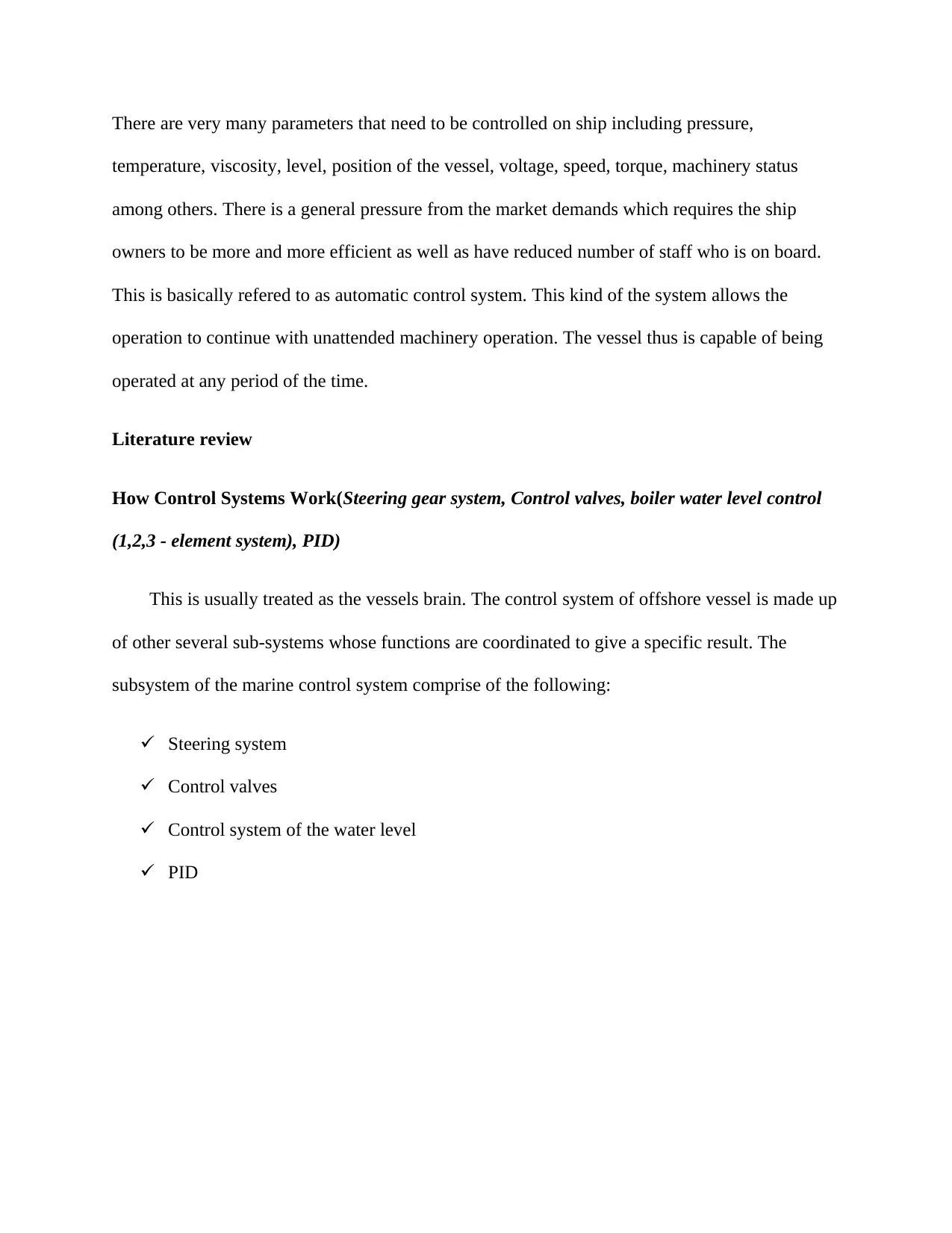
There are very many parameters that need to be controlled on ship including pressure,
temperature, viscosity, level, position of the vessel, voltage, speed, torque, machinery status
among others. There is a general pressure from the market demands which requires the ship
owners to be more and more efficient as well as have reduced number of staff who is on board.
This is basically refered to as automatic control system. This kind of the system allows the
operation to continue with unattended machinery operation. The vessel thus is capable of being
operated at any period of the time.
Literature review
How Control Systems Work(Steering gear system, Control valves, boiler water level control
(1,2,3 - element system), PID)
This is usually treated as the vessels brain. The control system of offshore vessel is made up
of other several sub-systems whose functions are coordinated to give a specific result. The
subsystem of the marine control system comprise of the following:
Steering system
Control valves
Control system of the water level
PID
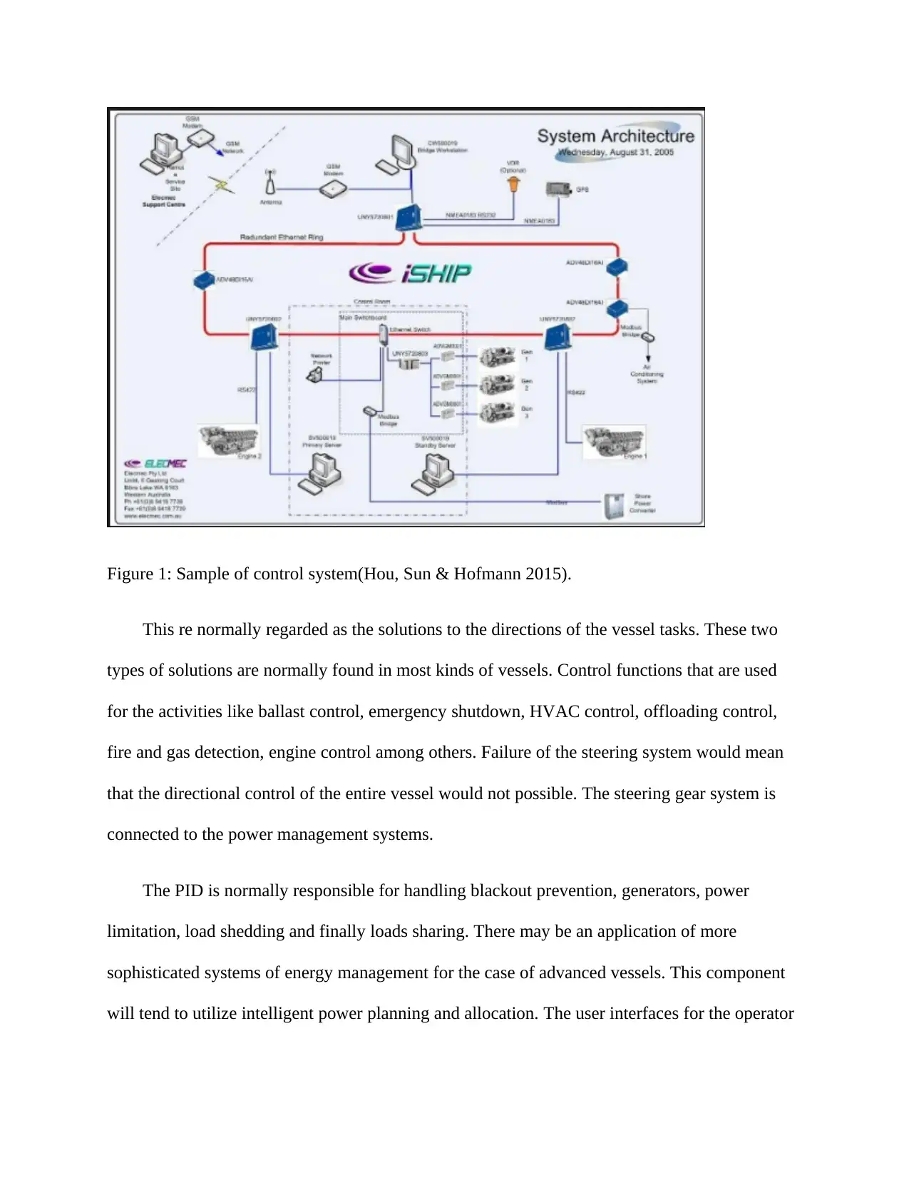
Figure 1: Sample of control system(Hou, Sun & Hofmann 2015).
This re normally regarded as the solutions to the directions of the vessel tasks. These two
types of solutions are normally found in most kinds of vessels. Control functions that are used
for the activities like ballast control, emergency shutdown, HVAC control, offloading control,
fire and gas detection, engine control among others. Failure of the steering system would mean
that the directional control of the entire vessel would not possible. The steering gear system is
connected to the power management systems.
The PID is normally responsible for handling blackout prevention, generators, power
limitation, load shedding and finally loads sharing. There may be an application of more
sophisticated systems of energy management for the case of advanced vessels. This component
will tend to utilize intelligent power planning and allocation. The user interfaces for the operator
⊘ This is a preview!⊘
Do you want full access?
Subscribe today to unlock all pages.
Trusted by 1+ million students worldwide

to the system of automation is normally provided through Human-Machine Interface that has
operator panels and display systems.
Control system of the water level determines the level of sailing of the vessel while in
water. By the use of sensors, the level of the water is constantly monitored. This system is
connected to centralize Computers with scalable I/O capacities and CPU processing that are
commonly denoted as process control stations or controllers. Distributed computers that are
commonly known as PLCs that have interfaces and local control to be used in the processing and
centralizing other computers. Failure of the Control system of the water level would mean the
vessel knocking itself on the icebergs and rocks underneath which will to accidents.
Control valves usually communication buses at different control levels. This is also associated
cabling, cable routing, and segregation. The control values ensure that pneumatic system and
thus the entire control system function effectively.
How control system fails
Steering gear failure:
Steering system failure is usually as a result of the malfunctioning of the valves that are usually
meant for safety. These valves are commonly called pass valve system. In case any problem is
noted is realized in the control system, the lever will have unsatisfactory steering.
Solution of the steering gear failure
The issue of the steering gear failure can be effectively controlled by having the pass valve as
well as safety valve effectively checked at regular intervals. The adjustment of the repeat back
lever as well as the turn buckle lever is adjusted accordingly.
Paraphrase This Document
Need a fresh take? Get an instant paraphrase of this document with our AI Paraphraser
Control Valve Failure
In the control system of the ship, valve usually fails because of the reasons:
Corrosion as well as wear of the elastomers with time. Also when the pressure and temperature
of the system go beyond the design parameters especially in the case of pipelines, the unexpected
pressure spikes occurs. Presence of abrasive and other foreign debris materials in the pipeline
can lead to valve failure. The incorrect assembly of the components can also lead to the failure of
the control valve.
Solution
The working fluid of the pneumatic system of the ship should be cleaned properly during the
maintenance exercise. The maintenance operations should involve replacement of the worn out
components or parts of the control valves.
Boiler Water level control Failure system
One of the most important technological elements of the boiler control system is called drum.
The drum has a water gauge as well as a diagnostic system which is responsible for the
initialization of the boiler disconnection in case the water level rises too high or falls. Lose
connection of the gauge system and the drum usually leads to the boiler control failure. Physical
damage like rusting can also lead to the system failure.
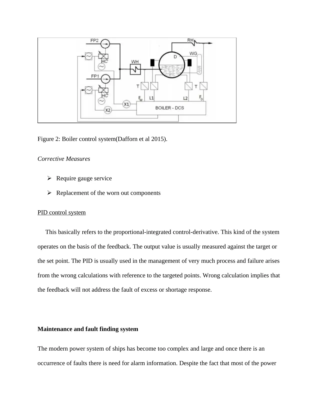
Figure 2: Boiler control system(Dafforn et al 2015).
Corrective Measures
Require gauge service
Replacement of the worn out components
PID control system
This basically refers to the proportional-integrated control-derivative. This kind of the system
operates on the basis of the feedback. The output value is usually measured against the target or
the set point. The PID is usually used in the management of very much process and failure arises
from the wrong calculations with reference to the targeted points. Wrong calculation implies that
the feedback will not address the fault of excess or shortage response.
Maintenance and fault finding system
The modern power system of ships has become too complex and large and once there is an
occurrence of faults there is need for alarm information. Despite the fact that most of the power
⊘ This is a preview!⊘
Do you want full access?
Subscribe today to unlock all pages.
Trusted by 1+ million students worldwide
monitoring systems of the ship have relatively simple systems of fault diagnosis, they only give
numerous and unselective alarm information to the crew. It becomes therefore very difficult for
the crew to quickly and accurately determine the fault. This makes the research on the fault
finding and diagnosis technique to be one of the interesting topics. This can effectively assist the
crew on board to handle completely the power system fault, prevent fault expansion and finally
shorten the processing time.
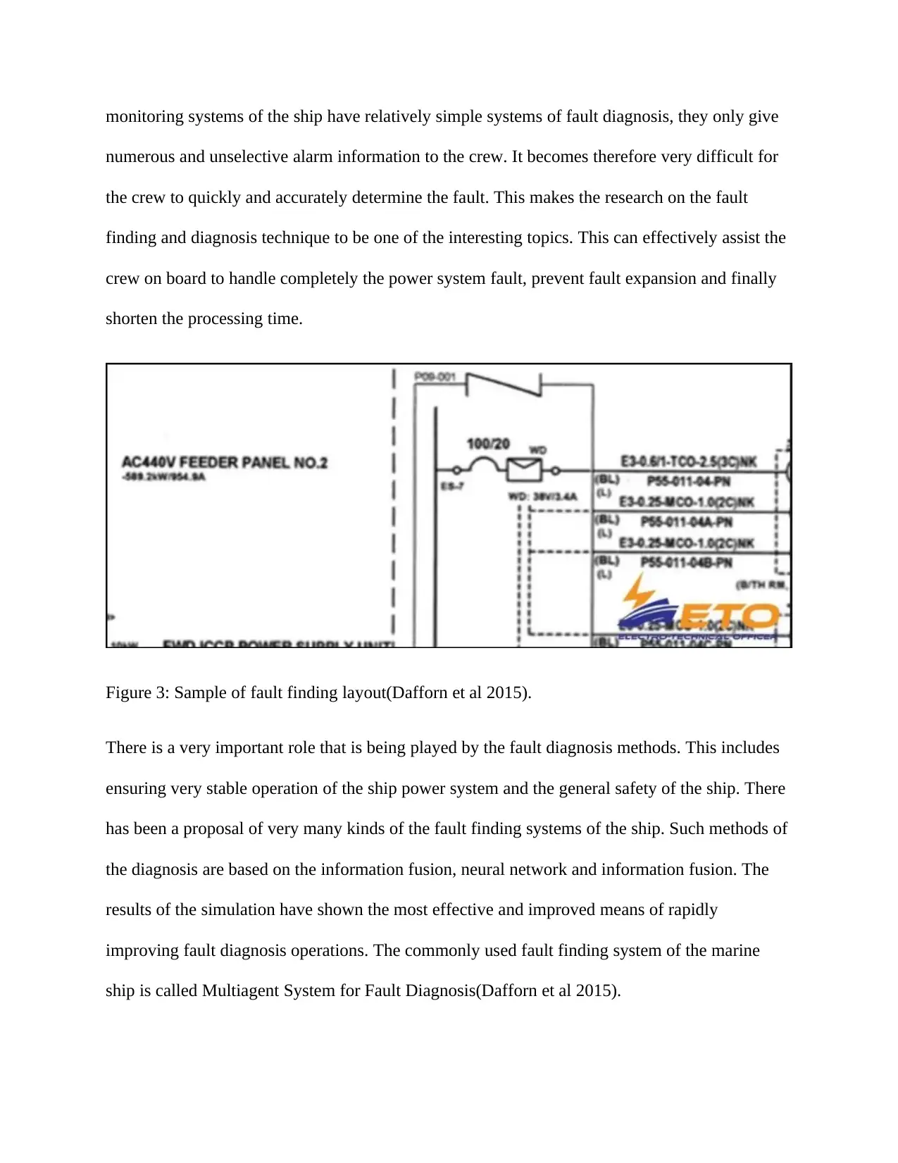
Figure 3: Sample of fault finding layout(Dafforn et al 2015).
There is a very important role that is being played by the fault diagnosis methods. This includes
ensuring very stable operation of the ship power system and the general safety of the ship. There
has been a proposal of very many kinds of the fault finding systems of the ship. Such methods of
the diagnosis are based on the information fusion, neural network and information fusion. The
results of the simulation have shown the most effective and improved means of rapidly
improving fault diagnosis operations. The commonly used fault finding system of the marine
ship is called Multiagent System for Fault Diagnosis(Dafforn et al 2015).
numerous and unselective alarm information to the crew. It becomes therefore very difficult for
the crew to quickly and accurately determine the fault. This makes the research on the fault
finding and diagnosis technique to be one of the interesting topics. This can effectively assist the
crew on board to handle completely the power system fault, prevent fault expansion and finally
shorten the processing time.
Figure 3: Sample of fault finding layout(Dafforn et al 2015).
There is a very important role that is being played by the fault diagnosis methods. This includes
ensuring very stable operation of the ship power system and the general safety of the ship. There
has been a proposal of very many kinds of the fault finding systems of the ship. Such methods of
the diagnosis are based on the information fusion, neural network and information fusion. The
results of the simulation have shown the most effective and improved means of rapidly
improving fault diagnosis operations. The commonly used fault finding system of the marine
ship is called Multiagent System for Fault Diagnosis(Dafforn et al 2015).
Paraphrase This Document
Need a fresh take? Get an instant paraphrase of this document with our AI Paraphraser
This particular system (. Multiagent System for Fault Diagnosis) normally originate from the
artificial intelligence system. As a result of its advantages, it is now the domain of the control
system of all other activities of the ship(Hou, Sun & Hofmann 2014) Multiagent System for
Fault Diagnosis is a loose coupling network that constitutes several agents. These agents are
logically or physically scattered with their behavior being self-governing. This implies that their
operations and behavior are never the influence of another restrictive controller(Strain et
al.2018). In order to effectively achieve the task of fault finding, all the agent are normally linked
together but under a specific type of control which functions in a protocol manner. They are
therefore capable of solving more than a single agent by cooperation and
communication(Wang,Kim & Kim 2014).
Major functions of Multiagent System for Fault Diagnosis
The core objective of.Multiagent System for Fault Diagnosis is to locate the position or to find
out the fault within the power system of the ship in real time before the fault can be isolated and
excluded. In order to ensure that there is much stable operation of SPS, the key activities of the
fault system diagnosis that will be required include:
Fault detection through monitoring: Each and every agent of Multiagent System for Fault
Diagnosis collect information on faults in the system and communicate with other systems
regarding the level of the fault detected(Daboussi, et al.2014).
Real-time notification of fault: There is normally deliverance of simple information regarding
fault to the SCM –agent before implementation of complex diagnosis is done by FDI-Agent.
This leads to the display of alarm immediately on the GUI for the maintenance activities to be
carried out. This allows for the timely maintenance process to be carried out.
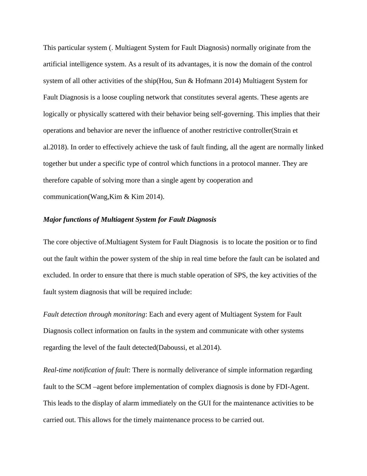
Active alarm list and alarm status setting: The setting of the status of the alarm of any
corresponding device after the fault alarm has successfully conveyed the information. This will
extend to the storage of information on the alarm for future reference.
Control system failure related Accidents
Case study
A product tanker of Mars 200827 was making the final approach to the jetties when all of a
sudden and without warning there was lost of the control of podded propulsion system the vessel.
This led to the vessel having several contacts with the infrastructure of the jetty. There was
material damage of vessel and jetty just before the control could be regained (Hou, Sun &
Hofmann 2014).
The pilot and the master were on the bridge when the accident was occurring. Due to the proper
slow speed qualities of the ship in maneuvering the propulsion system of the pod and the
effectiveness of the bow thruster, the tag had not been engaged. There was transfer of the
conning position from the center to the port control console by the master as the vessel
approached the jetty(Kanellos, Prousalidis & Tsekouras 2014). This was being done in
preparation for berthing the port side of the vessel.
Just when the vessel was nearly 100m from the jetty and at a velocity of 1.2knots, there was an
undefined movement of the control lever on its own to approximately 70 percent of its full
power. This particular pod had actually been angled to assist in thrusting the stern of the vessel
away from the infrastructure of jetties and as there was a sudden increase of the speed by the
tanker, the bow swung very fast to the port(Flores et al.2015). There were attempts by the master
to pull control lever to zero but power remained at 70 percent and the concrete apron of the jetty
⊘ This is a preview!⊘
Do you want full access?
Subscribe today to unlock all pages.
Trusted by 1+ million students worldwide
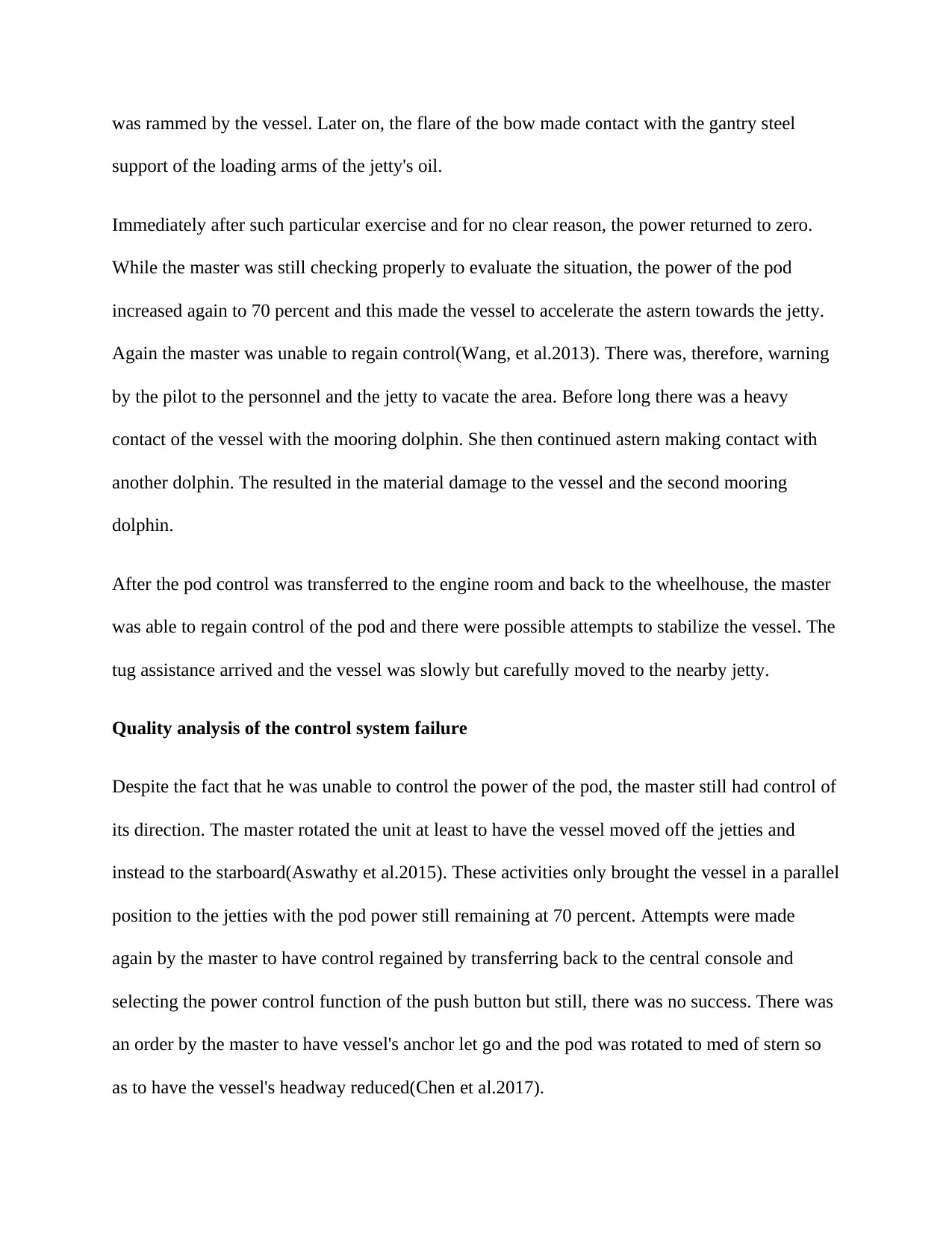
was rammed by the vessel. Later on, the flare of the bow made contact with the gantry steel
support of the loading arms of the jetty's oil.
Immediately after such particular exercise and for no clear reason, the power returned to zero.
While the master was still checking properly to evaluate the situation, the power of the pod
increased again to 70 percent and this made the vessel to accelerate the astern towards the jetty.
Again the master was unable to regain control(Wang, et al.2013). There was, therefore, warning
by the pilot to the personnel and the jetty to vacate the area. Before long there was a heavy
contact of the vessel with the mooring dolphin. She then continued astern making contact with
another dolphin. The resulted in the material damage to the vessel and the second mooring
dolphin.
After the pod control was transferred to the engine room and back to the wheelhouse, the master
was able to regain control of the pod and there were possible attempts to stabilize the vessel. The
tug assistance arrived and the vessel was slowly but carefully moved to the nearby jetty.
Quality analysis of the control system failure
Despite the fact that he was unable to control the power of the pod, the master still had control of
its direction. The master rotated the unit at least to have the vessel moved off the jetties and
instead to the starboard(Aswathy et al.2015). These activities only brought the vessel in a parallel
position to the jetties with the pod power still remaining at 70 percent. Attempts were made
again by the master to have control regained by transferring back to the central console and
selecting the power control function of the push button but still, there was no success. There was
an order by the master to have vessel's anchor let go and the pod was rotated to med of stern so
as to have the vessel's headway reduced(Chen et al.2017).
Paraphrase This Document
Need a fresh take? Get an instant paraphrase of this document with our AI Paraphraser
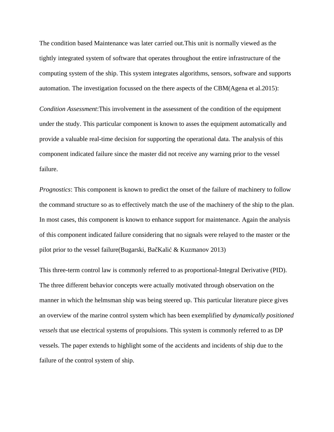
The condition based Maintenance was later carried out.This unit is normally viewed as the
tightly integrated system of software that operates throughout the entire infrastructure of the
computing system of the ship. This system integrates algorithms, sensors, software and supports
automation. The investigation focussed on the there aspects of the CBM(Agena et al.2015):
Condition Assessment:This involvement in the assessment of the condition of the equipment
under the study. This particular component is known to asses the equipment automatically and
provide a valuable real-time decision for supporting the operational data. The analysis of this
component indicated failure since the master did not receive any warning prior to the vessel
failure.
Prognostics: This component is known to predict the onset of the failure of machinery to follow
the command structure so as to effectively match the use of the machinery of the ship to the plan.
In most cases, this component is known to enhance support for maintenance. Again the analysis
of this component indicated failure considering that no signals were relayed to the master or the
pilot prior to the vessel failure(Bugarski, BačKalić & Kuzmanov 2013)
This three-term control law is commonly referred to as proportional-Integral Derivative (PID).
The three different behavior concepts were actually motivated through observation on the
manner in which the helmsman ship was being steered up. This particular literature piece gives
an overview of the marine control system which has been exemplified by dynamically positioned
vessels that use electrical systems of propulsions. This system is commonly referred to as DP
vessels. The paper extends to highlight some of the accidents and incidents of ship due to the
failure of the control system of ship.
Figure 4:Conditional basement maintainance system(Dafforn et al 2015)
Upon the investigation, it was established that the accident was due to the failed controlled
system. When the control system of the vessel failed, there were no alerts to the master
concerning the failure. Also, there was no warning before the pod could begin to change power
by itself.
Conclusions
There are continuous deliberate efforts by the distributed control system suppliers to
continuously provide more predictive features that can assist the users of these same systems to
obtain a host of other information from the automation environment. The advent of the smart
sensors is expected to bring changes in the entire sector since they are capable of communicating
through the networks of the system. The overall goal is to analyze the changes in the equipment's
⊘ This is a preview!⊘
Do you want full access?
Subscribe today to unlock all pages.
Trusted by 1+ million students worldwide
1 out of 16

Your All-in-One AI-Powered Toolkit for Academic Success.
+13062052269
info@desklib.com
Available 24*7 on WhatsApp / Email
![[object Object]](/_next/static/media/star-bottom.7253800d.svg)
Unlock your academic potential
Copyright © 2020–2026 A2Z Services. All Rights Reserved. Developed and managed by ZUCOL.