Report: 12 Pulse AC/DC Converter and Single Phase Inverter Analysis

Verified

Added on  2022/01/03

|6
|1251
|30
Report
AI Summary
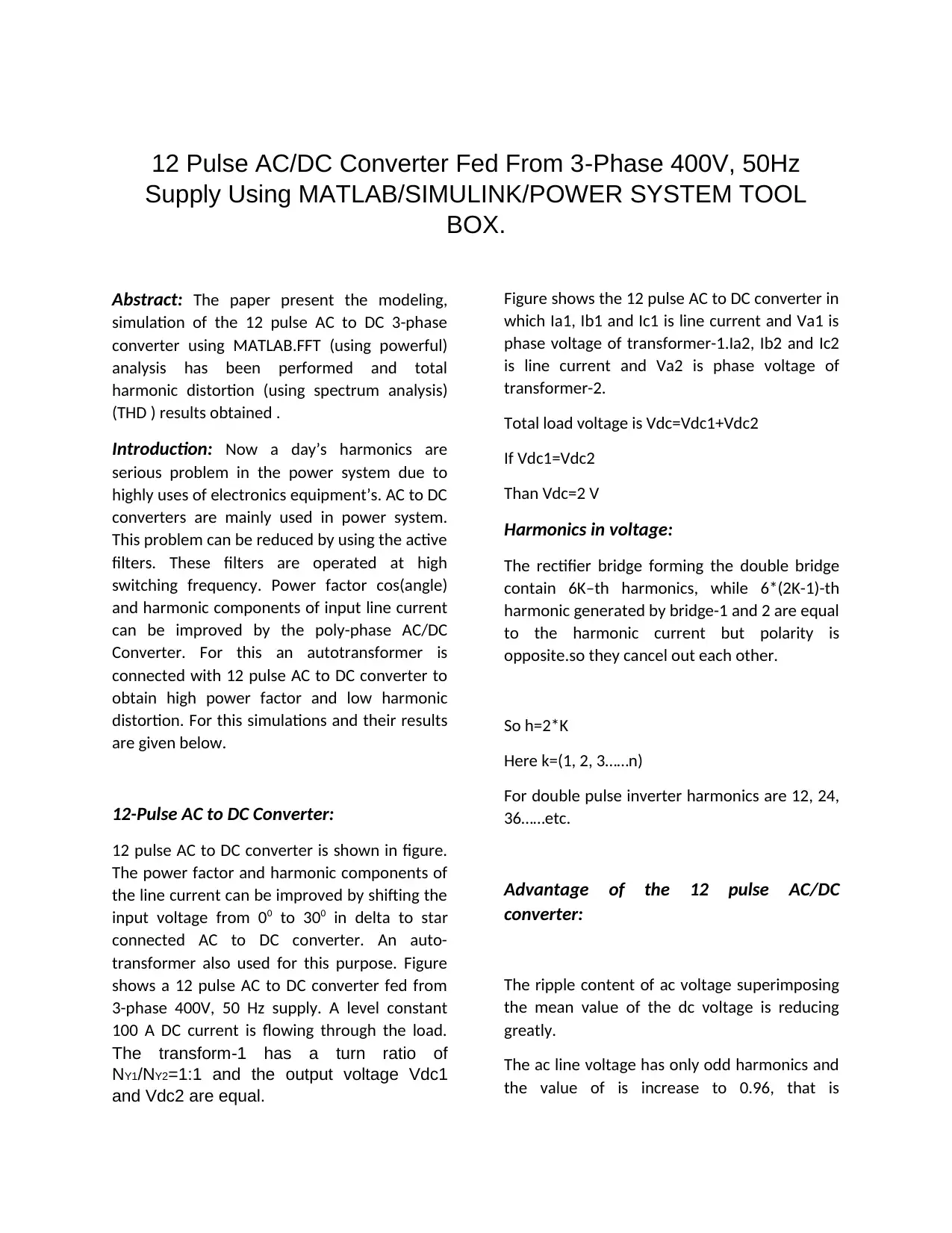
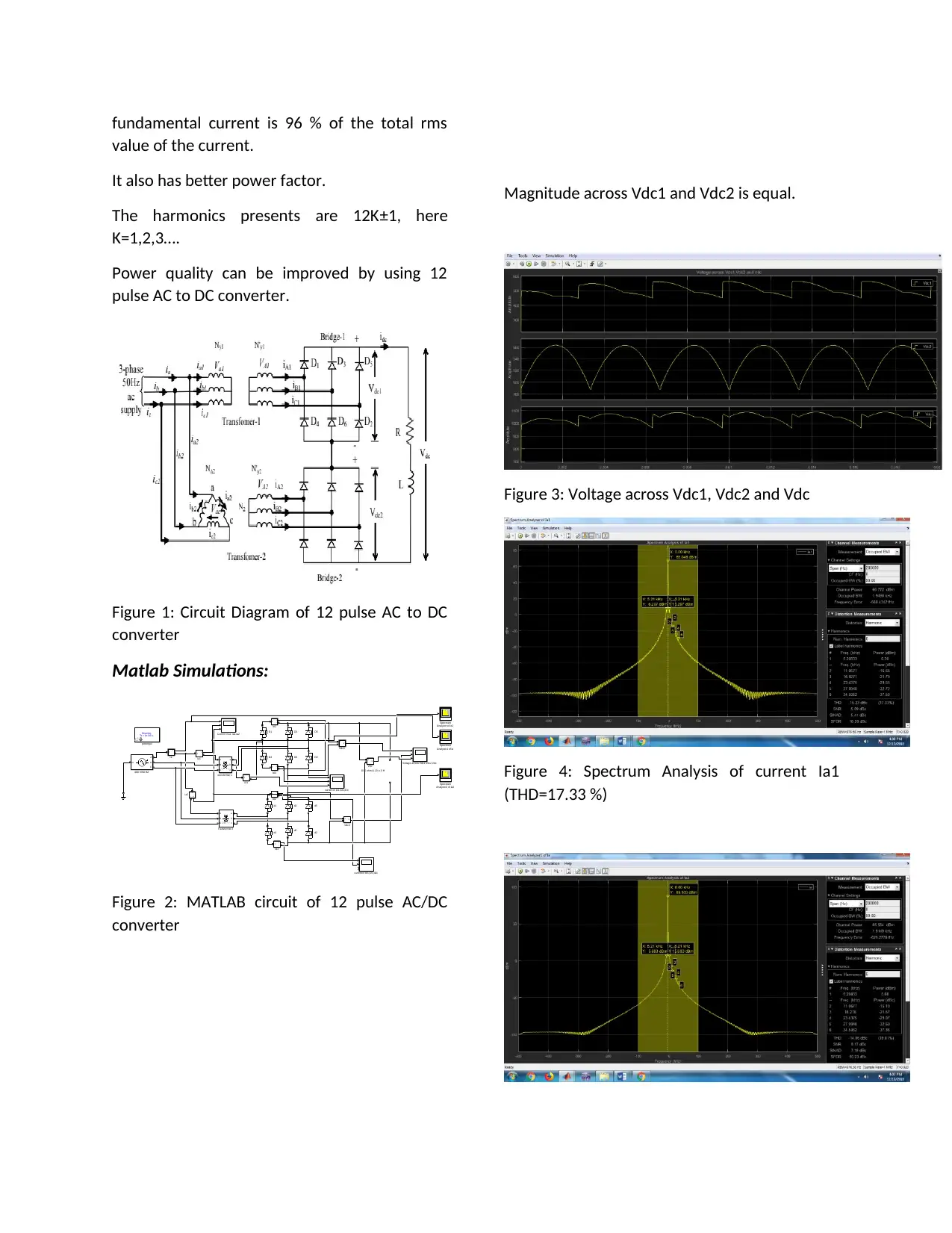
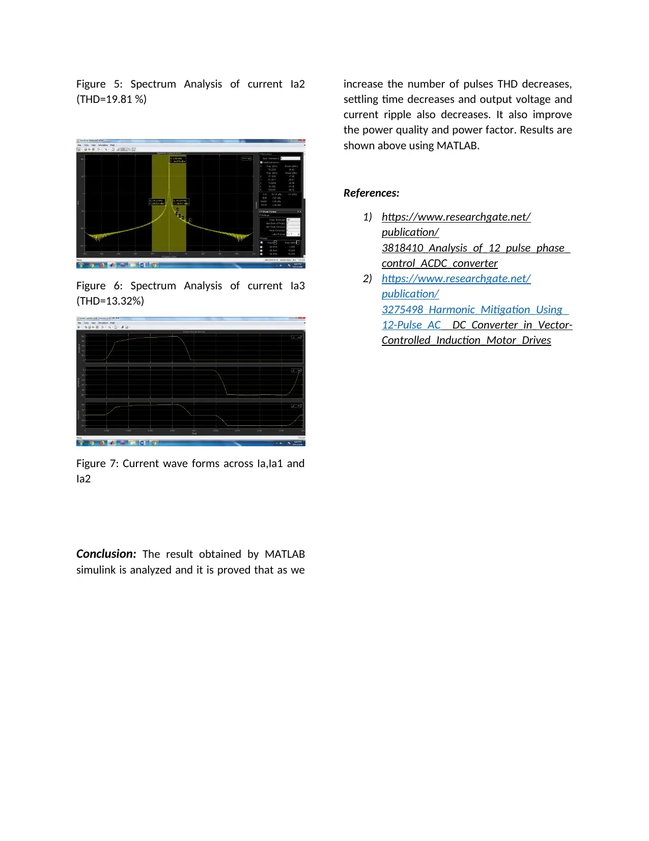
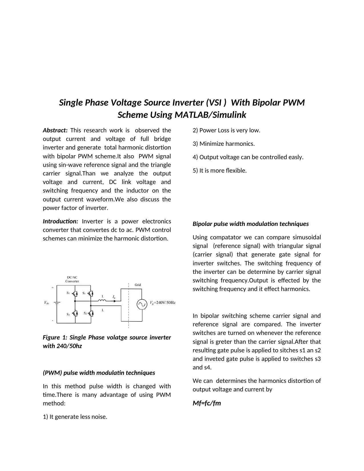
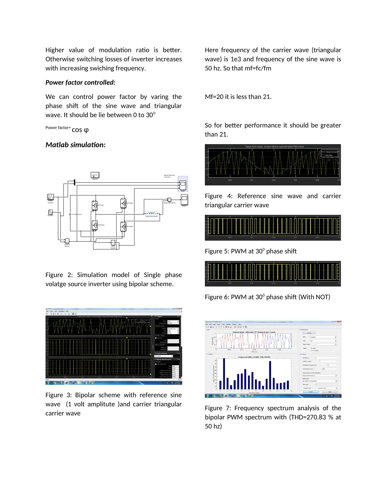
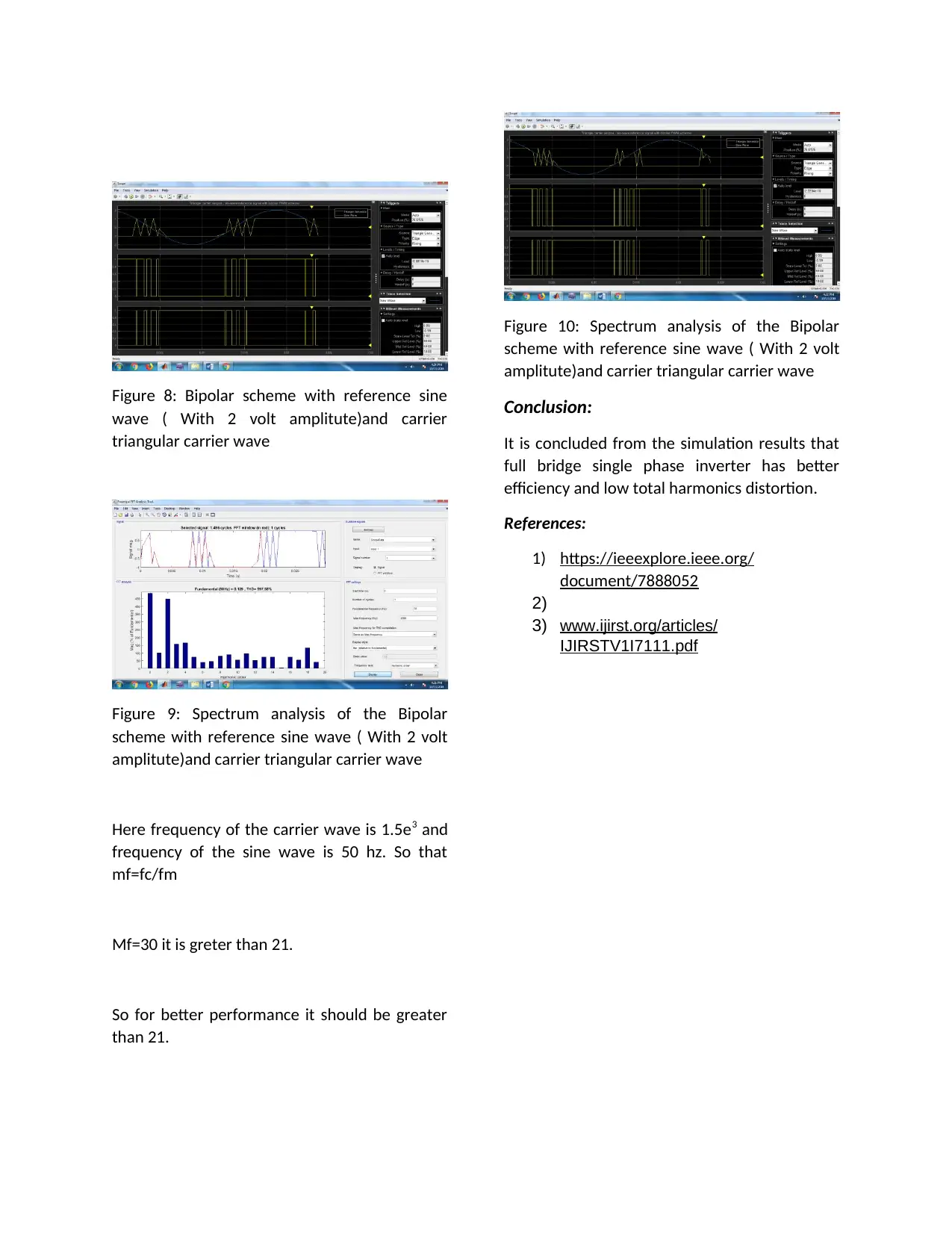
This report presents a detailed analysis of two key power electronics components: a 12-pulse AC/DC converter and a single-phase voltage source inverter (VSI). The 12-pulse AC/DC converter analysis, fed from a 3-phase 400V, 50Hz supply, focuses on the reduction of harmonic distortion and improvement of power factor using an autotransformer. MATLAB/Simulink simulations are used to demonstrate the converter's performance, including FFT analysis for Total Harmonic Distortion (THD) results. The second part of the report investigates a single-phase VSI with a bipolar PWM scheme. It examines the output voltage and current, THD, PWM signal generation using sine-wave and triangular carrier signals, and the impact of switching frequency and modulation ratio on inverter performance. The report also discusses power factor control techniques. MATLAB simulations are used to validate the analysis, with results showing the impact of different parameters on the output waveforms and harmonic content. The report concludes by highlighting the advantages of both the 12-pulse AC/DC converter and the single-phase inverter in terms of power quality and efficiency.
tabler-icon-diamond-filled.svg

Contribute Materials

Your contribution can guide someone’s learning journey. Share your documents today.
Document Page
12 Pulse AC/DC Converter Fed From 3Phase 400V, 50Hz
Supply Using MATLAB/SIMULINK/POWER SYSTEM TOOL
BOX.
Abstract: The paper present the modeling,
simulation of the 12 pulse AC to DC 3-phase
converter using MATLAB.FFT (using powerful)
analysis has been performed and total
harmonic distortion (using spectrum analysis)
(THD ) results obtained .
Introduction: Now a day’s harmonics are
serious problem in the power system due to
highly uses of electronics equipment’s. AC to DC
converters are mainly used in power system.
This problem can be reduced by using the active
filters. These filters are operated at high
switching frequency. Power factor cos(angle)
and harmonic components of input line current
can be improved by the poly-phase AC/DC
Converter. For this an autotransformer is
connected with 12 pulse AC to DC converter to
obtain high power factor and low harmonic
distortion. For this simulations and their results
are given below.
12-Pulse AC to DC Converter:
12 pulse AC to DC converter is shown in figure.
The power factor and harmonic components of
the line current can be improved by shifting the
input voltage from 00 to 300 in delta to star
connected AC to DC converter. An auto-
transformer also used for this purpose. Figure
shows a 12 pulse AC to DC converter fed from
3-phase 400V, 50 Hz supply. A level constant
100 A DC current is flowing through the load.
The transform1 has a turn ratio of
NY1/NY2=1:1 and the output voltage Vdc1
and Vdc2 are equal.
Figure shows the 12 pulse AC to DC converter in
which Ia1, Ib1 and Ic1 is line current and Va1 is
phase voltage of transformer-1.Ia2, Ib2 and Ic2
is line current and Va2 is phase voltage of
transformer-2.
Total load voltage is Vdc=Vdc1+Vdc2
If Vdc1=Vdc2
Than Vdc=2 V
Harmonics in voltage:
The rectifier bridge forming the double bridge
contain 6K–th harmonics, while 6*(2K-1)-th
harmonic generated by bridge-1 and 2 are equal
to the harmonic current but polarity is
opposite.so they cancel out each other.
So h=2*K
Here k=(1, 2, 3……n)
For double pulse inverter harmonics are 12, 24,
36……etc.
Advantage of the 12 pulse AC/DC
converter:
The ripple content of ac voltage superimposing
the mean value of the dc voltage is reducing
greatly.
The ac line voltage has only odd harmonics and
the value of is increase to 0.96, that is
tabler-icon-diamond-filled.svg

Secure Best Marks with AI Grader

Need help grading? Try our AI Grader for instant feedback on your assignments.
Document Page
fundamental current is 96 % of the total rms
value of the current.
It also has better power factor.
The harmonics presents are 12K±1, here
K=1,2,3….
Power quality can be improved by using 12
pulse AC to DC converter.
Figure 1: Circuit Diagram of 12 pulse AC to DC
converter
Matlab Simulations:
Discrete,
Ts = 1e-06 s.
powergui
A
B
C
a
b
cD11 Y
Transformer 2
A
B
C
a
b
cY Y
transformer 1
D1 D3
D4 D6
d1
d6
d3
i
+ -
ia
v
+
-
Vdc1
N
A
B
C
400 V/50 HZ
v
+
-
Vdc2
v
+
-
Vdc
D5
D2
d2
d5
+
10.5 ohm & 20 e-3 H
i
+ -
ia1
i +
-ia2
Current in ia, ia1,ia2
Voltage across Vdc1,Vdc2,Vdc
d4
i
+ -
iA1
i
+ -
Id4
i
+ -
id1
current in IA1,ID1,ID4
Spectrum
Analyzer of Ia1
Spectrum
Analyzer1 of Ia
Spectrum
Analyzer2 of Ia2
i
+ -
id2
i
+ -
id3
current in IA1,ID1,ID1
Figure 2: MATLAB circuit of 12 pulse AC/DC
converter
Magnitude across Vdc1 and Vdc2 is equal.
Figure 3: Voltage across Vdc1, Vdc2 and Vdc
Figure 4: Spectrum Analysis of current Ia1
(THD=17.33 %)
Document Page
Figure 5: Spectrum Analysis of current Ia2
(THD=19.81 %)
Figure 6: Spectrum Analysis of current Ia3
(THD=13.32%)
Figure 7: Current wave forms across Ia,Ia1 and
Ia2
Conclusion: The result obtained by MATLAB
simulink is analyzed and it is proved that as we
increase the number of pulses THD decreases,
settling time decreases and output voltage and
current ripple also decreases. It also improve
the power quality and power factor. Results are
shown above using MATLAB.
References:
1) https://www.researchgate.net/
publication/
3818410_Analysis_of_12_pulse_phase_
control_ACDC_converter
2) https://www.researchgate.net/
publication/
3275498_Harmonic_Mitigation_Using_
12-Pulse_AC DC_Converter_in_Vector-
Controlled_Induction_Motor_Drives
Document Page
Single Phase Voltage Source Inverter (VSI ) With Bipolar PWM
Scheme Using MATLAB/Simulink
Abstract: This research work is observed the
output current and voltage of full bridge
inverter and generate total harmonic distortion
with bipolar PWM scheme.It also PWM signal
using sin-wave reference signal and the triangle
carrier signal.Than we analyze the output
voltage and current, DC link voltage and
switching frequency and the inductor on the
output current waveform.We also discuss the
power factor of inverter.
Introduction: Inverter is a power electronics
converter that convertes dc to ac. PWM control
schemes can minimize the harmonic distortion.
Figure 1: Single Phase volatge source inverter
with 240/50hz
(PWM) pulse width modulatin techniques
In this method pulse width is changed with
time.There is many advantage of using PWM
method:
1) It generate less noise.
2) Power Loss is very low.
3) Minimize harmonics.
4) Output voltage can be controlled easly.
5) It is more flexible.
Bipolar pulse width modulation techniques
Using compatator we can compare simusoidal
signal (reference signal) with triangular signal
(carrier signal) that generate gate signal for
inverter switches. The switching frequency of
the inverter can be determine by carrier signal
switching frequency.Output is effected by the
switching frequency and it effect harmonics.
In bipolar switching scheme carrier signal and
reference signal are compared. The inverter
switches are turned on whenever the reference
signal is greter than the carrier signal.After that
resulting gate pulse is applied to sitches s1 an s2
and inveted gate pulse is applied to switches s3
and s4.
We can determines the harmonics distortion of
output voltage and current by
Mf=fc/fm
tabler-icon-diamond-filled.svg

Secure Best Marks with AI Grader

Need help grading? Try our AI Grader for instant feedback on your assignments.
Document Page
Higher value of modulation ratio is better.
Otherwise switching losses of inverter increases
with increasing swiching frequency.
Power factor controlled:
We can control power factor by varing the
phase shift of the sine wave and triangular
wave. It should be lie between 0 to 300
Power factor= cos φ
Matlab simulation:
bipolar PWM invter
wave forms
g m
C E
IGBT/Diode
g m
C E
IGBT/Diode1
g m
C E
IGBT/Diode2
g m
C E
IGBT/Diode3
+
Serie10s RLC Branch
DC Voltage Source
Triangle
Generator
Sine Wave
NOT
Logical
Operator
<=
Relational
Operator
v
+
-
Voltage Measurement
Scope
Scope1
Continuous
powergui
Figure 2: Simulation model of Single phase
volatge source inverter using bipolar scheme.
Figure 3: Bipolar scheme with reference sine
wave (1 volt amplitute )and carrier triangular
carrier wave
Here frequency of the carrier wave (triangular
wave) is 1e3 and frequency of the sine wave is
50 hz. So that mf=fc/fm
Mf=20 it is less than 21.
So for better performance it should be greater
than 21.
0 0.005 0.01 0.015 0.02 0.025 0.03
-1
-0.5
0
0.5
1
Triangle carrier singnal , sin-wave reference signal with bipolar PWM scheme
Triangle Generator
Sine Wave
Figure 4: Reference sine wave and carrier
triangular carrier wave
0 0.005 0.01 0.015 0.02 0.025 0.03
0
0.2
0.4
0.6
0.8
1
Figure 5: PWM at 300 phase shift
0 0.005 0.01 0.015 0.02 0.025 0.03
0
0.2
0.4
0.6
0.8
1
Figure 6: PWM at 300 phase shift (With NOT)
Figure 7: Frequency spectrum analysis of the
bipolar PWM spectrum with (THD=270.83 % at
50 hz)
Document Page
Figure 8: Bipolar scheme with reference sine
wave ( With 2 volt amplitute)and carrier
triangular carrier wave
Figure 9: Spectrum analysis of the Bipolar
scheme with reference sine wave ( With 2 volt
amplitute)and carrier triangular carrier wave
Here frequency of the carrier wave is 1.5e3 and
frequency of the sine wave is 50 hz. So that
mf=fc/fm
Mf=30 it is greter than 21.
So for better performance it should be greater
than 21.
Figure 10: Spectrum analysis of the Bipolar
scheme with reference sine wave ( With 2 volt
amplitute)and carrier triangular carrier wave
Conclusion:
It is concluded from the simulation results that
full bridge single phase inverter has better
efficiency and low total harmonics distortion.
References:
1) https://ieeexplore.ieee.org/
document/7888052
2)
3) www.ijirst.org/articles/
IJIRSTV1I7111.pdf
chevron_up_icon
1 out of 6
circle_padding
hide_on_mobile
zoom_out_icon
logo.png

Your All-in-One AI-Powered Toolkit for Academic Success.

Available 24*7 on WhatsApp / Email

[object Object]