Single Storey House Dwelling Assessment Report
VerifiedAdded on 2019/10/30
|8
|2442
|150
Report
AI Summary
This report provides a detailed assessment of a single-story house dwelling's design against the Australian Building Codes and Standards (BCA). The assessment covers various elements, including wind load calculations, structural integrity checks (waffle pod slab, timber floor design, footing system), bracing plans (AS 1684 compliance), and compliance with relevant Australian Standards (AS 2870, AS 3600). The report includes tables summarizing the assessment, detailing the actual assessment against the required provisions, and providing remarks and recommendations. Specific areas like earthworks, drainage, termite management, masonry construction, framing, wall cladding, glazing, fire safety, and wet area amenities are assessed. The report concludes with a discussion of the results, highlighting areas of compliance and areas needing improvement, and assigns an overall compliance score. The report emphasizes the importance of sustainable building practices and adherence to relevant codes and standards for ensuring public safety and wellbeing.
ASSESSMENT REPORT FOR A SINGLE STOREY HOUSE DWELLING
AS PER THE AUSTRALIAN BUIDLING CODES AND STANDARDS
INTRODUCTION
The work presented hereinafter dwells on the critical assessment aspects of the residential
building whose technical details have been provided to peruse and assess it against the set
standards namely: Building Code of Australia part 2 (BCA, 1996). Notably, the report pursues
various elements in the house against the given provisions to ascertain full compliance hence
such terms as “deem-to-satisfy” will be used accordingly in this context. Besides, calculations
will also be done and results presented in a manner that is understandable and in sync with the
sectional provisions. Hence the let the assessment work begin.
ASSESSMENT CRITERIA
Building Elements and Services
This section presents the various assessment outcomes vis-à-vis the appropriate codes and
standards. Hence the following are presented for further perusal:
(i) A complete full design check against the National Construction Code, Building
Code of Australia Volume 2 for all parts.
The NCA provides the general provisions for legal requirements in the building
sector. The BCA document is therefore a universal paraphernalia that envisages
harmony in building construction designs and development while ensuring public
safety and wellbeing are guaranteed in the developments.
This part, therefore, provides a concrete assessment of the identified elements as per
the building code of Australia (BCA).
For this part, table 1 gives the summary of the actual assessment and the specific
recommendations thereafter. It should be noted that full compliance includes the
conditional status of the surrounding hence issues like soil condition and natural
phenomena like earthquakes are included.
(ii) A complete waffle pod slab design as shown on the attached plans detailing and
confirming the slab thicknesses and reinforcement (top and bottom) using AS 2870.
Firstly, need to check the wind classification for the area (as provided by local
authorities); let it be fixed at N2 hence the following information can be retrieved (as
per 1684: 2 (2010):
Gust wind speed for:
Permissible stress = 33m/s
Serviceability limit state=26m/s
Ultimate limit state Vu= 40m/s
Paraphrase This Document
Need a fresh take? Get an instant paraphrase of this document with our AI Paraphraser
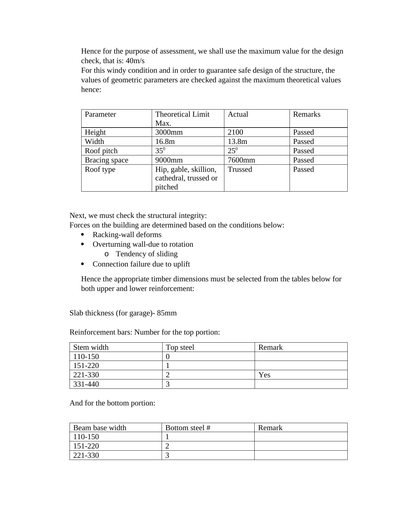
Hence for the purpose of assessment, we shall use the maximum value for the design
check, that is: 40m/s
For this windy condition and in order to guarantee safe design of the structure, the
values of geometric parameters are checked against the maximum theoretical values
hence:
Parameter Theoretical Limit
Max.
Actual Remarks
Height 3000mm 2100 Passed
Width 16.8m 13.8m Passed
Roof pitch 350 250 Passed
Bracing space 9000mm 7600mm Passed
Roof type Hip, gable, skillion,
cathedral, trussed or
pitched
Trussed Passed
Next, we must check the structural integrity:
Forces on the building are determined based on the conditions below:
Racking-wall deforms
Overturning wall-due to rotation
o Tendency of sliding
Connection failure due to uplift
Hence the appropriate timber dimensions must be selected from the tables below for
both upper and lower reinforcement:
Slab thickness (for garage)- 85mm
Reinforcement bars: Number for the top portion:
Stem width Top steel Remark
110-150 0
151-220 1
221-330 2 Yes
331-440 3
And for the bottom portion:
Beam base width Bottom steel # Remark
110-150 1
151-220 2
221-330 3
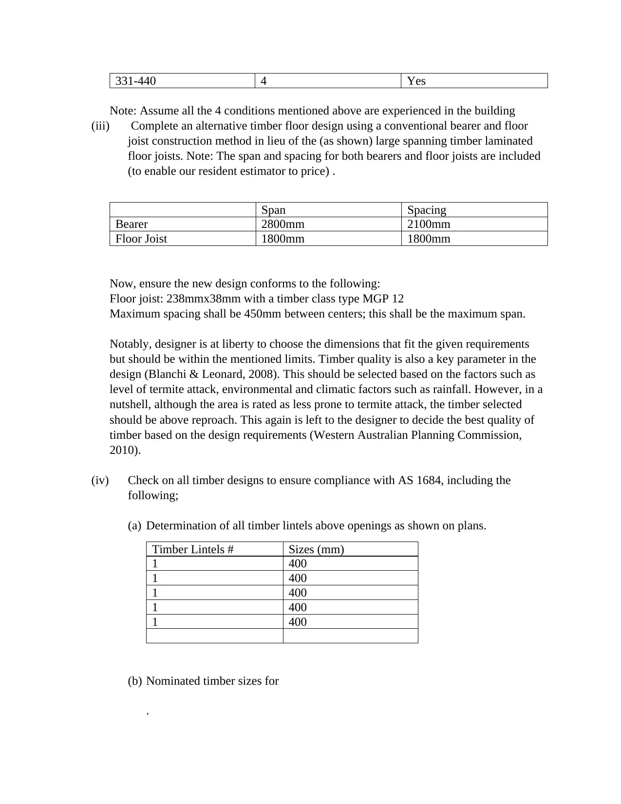
331-440 4 Yes
Note: Assume all the 4 conditions mentioned above are experienced in the building
(iii) Complete an alternative timber floor design using a conventional bearer and floor
joist construction method in lieu of the (as shown) large spanning timber laminated
floor joists. Note: The span and spacing for both bearers and floor joists are included
(to enable our resident estimator to price) .
Span Spacing
Bearer 2800mm 2100mm
Floor Joist 1800mm 1800mm
Now, ensure the new design conforms to the following:
Floor joist: 238mmx38mm with a timber class type MGP 12
Maximum spacing shall be 450mm between centers; this shall be the maximum span.
Notably, designer is at liberty to choose the dimensions that fit the given requirements
but should be within the mentioned limits. Timber quality is also a key parameter in the
design (Blanchi & Leonard, 2008). This should be selected based on the factors such as
level of termite attack, environmental and climatic factors such as rainfall. However, in a
nutshell, although the area is rated as less prone to termite attack, the timber selected
should be above reproach. This again is left to the designer to decide the best quality of
timber based on the design requirements (Western Australian Planning Commission,
2010).
(iv) Check on all timber designs to ensure compliance with AS 1684, including the
following;
(a) Determination of all timber lintels above openings as shown on plans.
Timber Lintels # Sizes (mm)
1 400
1 400
1 400
1 400
1 400
(b) Nominated timber sizes for
.
⊘ This is a preview!⊘
Do you want full access?
Subscribe today to unlock all pages.
Trusted by 1+ million students worldwide
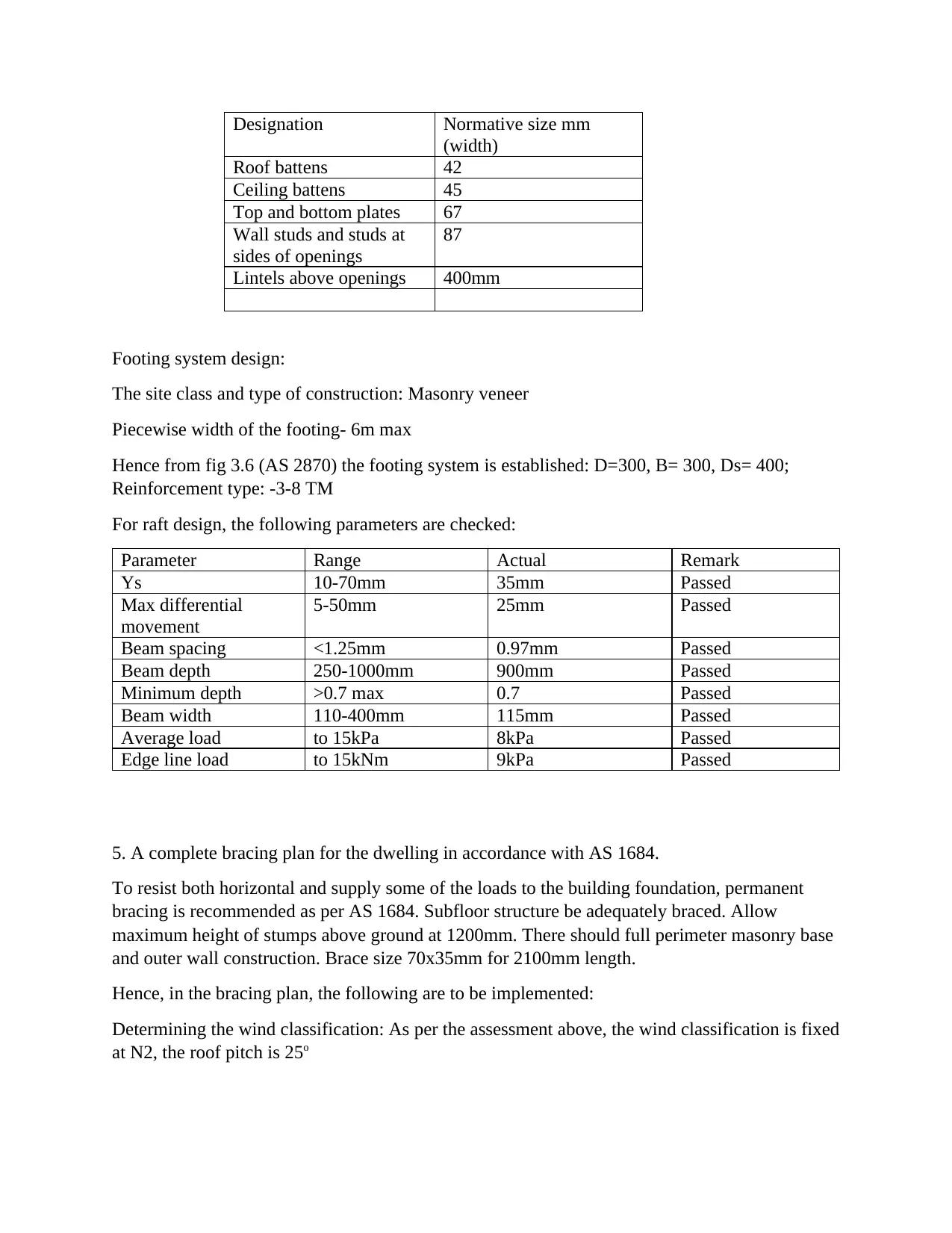
Designation Normative size mm
(width)
Roof battens 42
Ceiling battens 45
Top and bottom plates 67
Wall studs and studs at
sides of openings
87
Lintels above openings 400mm
Footing system design:
The site class and type of construction: Masonry veneer
Piecewise width of the footing- 6m max
Hence from fig 3.6 (AS 2870) the footing system is established: D=300, B= 300, Ds= 400;
Reinforcement type: -3-8 TM
For raft design, the following parameters are checked:
Parameter Range Actual Remark
Ys 10-70mm 35mm Passed
Max differential
movement
5-50mm 25mm Passed
Beam spacing <1.25mm 0.97mm Passed
Beam depth 250-1000mm 900mm Passed
Minimum depth >0.7 max 0.7 Passed
Beam width 110-400mm 115mm Passed
Average load to 15kPa 8kPa Passed
Edge line load to 15kNm 9kPa Passed
5. A complete bracing plan for the dwelling in accordance with AS 1684.
To resist both horizontal and supply some of the loads to the building foundation, permanent
bracing is recommended as per AS 1684. Subfloor structure be adequately braced. Allow
maximum height of stumps above ground at 1200mm. There should full perimeter masonry base
and outer wall construction. Brace size 70x35mm for 2100mm length.
Hence, in the bracing plan, the following are to be implemented:
Determining the wind classification: As per the assessment above, the wind classification is fixed
at N2, the roof pitch is 25o
Paraphrase This Document
Need a fresh take? Get an instant paraphrase of this document with our AI Paraphraser
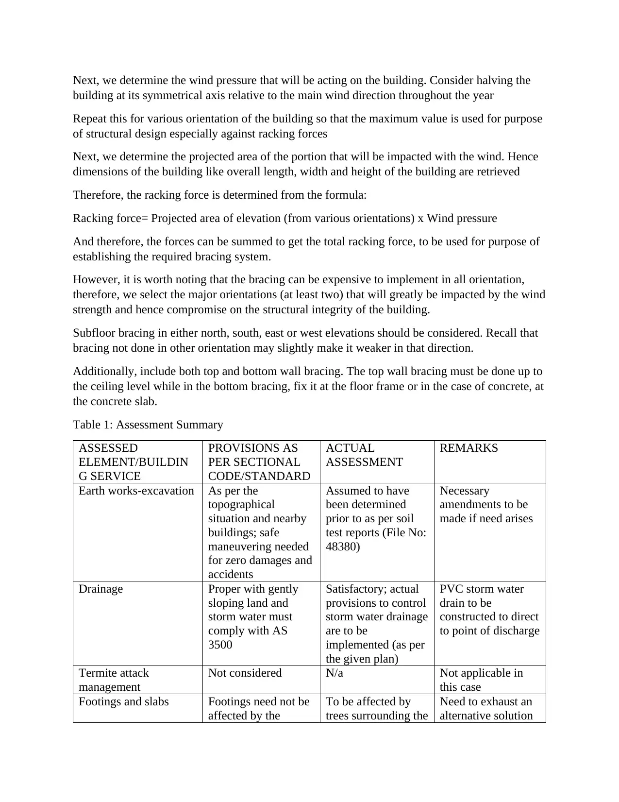
Next, we determine the wind pressure that will be acting on the building. Consider halving the
building at its symmetrical axis relative to the main wind direction throughout the year
Repeat this for various orientation of the building so that the maximum value is used for purpose
of structural design especially against racking forces
Next, we determine the projected area of the portion that will be impacted with the wind. Hence
dimensions of the building like overall length, width and height of the building are retrieved
Therefore, the racking force is determined from the formula:
Racking force= Projected area of elevation (from various orientations) x Wind pressure
And therefore, the forces can be summed to get the total racking force, to be used for purpose of
establishing the required bracing system.
However, it is worth noting that the bracing can be expensive to implement in all orientation,
therefore, we select the major orientations (at least two) that will greatly be impacted by the wind
strength and hence compromise on the structural integrity of the building.
Subfloor bracing in either north, south, east or west elevations should be considered. Recall that
bracing not done in other orientation may slightly make it weaker in that direction.
Additionally, include both top and bottom wall bracing. The top wall bracing must be done up to
the ceiling level while in the bottom bracing, fix it at the floor frame or in the case of concrete, at
the concrete slab.
Table 1: Assessment Summary
ASSESSED
ELEMENT/BUILDIN
G SERVICE
PROVISIONS AS
PER SECTIONAL
CODE/STANDARD
ACTUAL
ASSESSMENT
REMARKS
Earth works-excavation As per the
topographical
situation and nearby
buildings; safe
maneuvering needed
for zero damages and
accidents
Assumed to have
been determined
prior to as per soil
test reports (File No:
48380)
Necessary
amendments to be
made if need arises
Drainage Proper with gently
sloping land and
storm water must
comply with AS
3500
Satisfactory; actual
provisions to control
storm water drainage
are to be
implemented (as per
the given plan)
PVC storm water
drain to be
constructed to direct
to point of discharge
Termite attack
management
Not considered N/a Not applicable in
this case
Footings and slabs Footings need not be
affected by the
To be affected by
trees surrounding the
Need to exhaust an
alternative solution
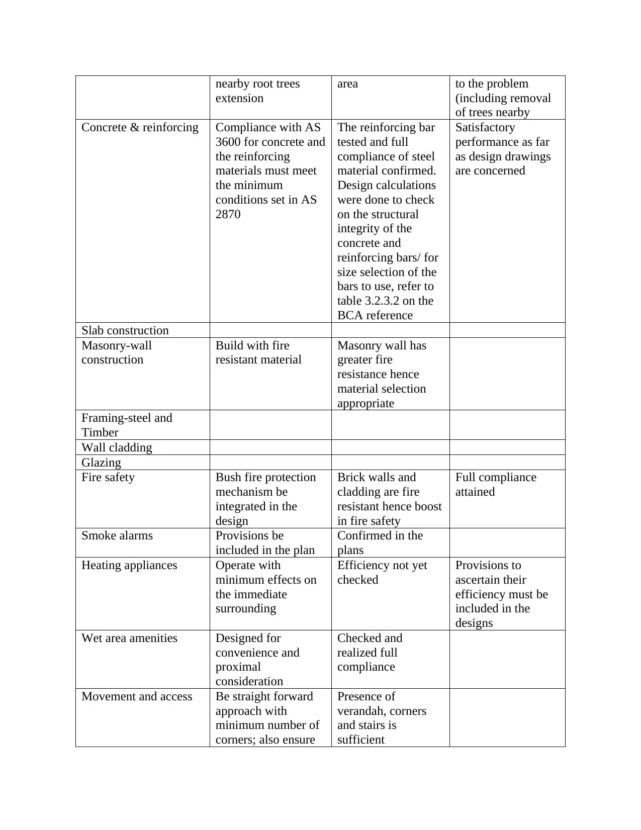
nearby root trees
extension
area to the problem
(including removal
of trees nearby
Concrete & reinforcing Compliance with AS
3600 for concrete and
the reinforcing
materials must meet
the minimum
conditions set in AS
2870
The reinforcing bar
tested and full
compliance of steel
material confirmed.
Design calculations
were done to check
on the structural
integrity of the
concrete and
reinforcing bars/ for
size selection of the
bars to use, refer to
table 3.2.3.2 on the
BCA reference
Satisfactory
performance as far
as design drawings
are concerned
Slab construction
Masonry-wall
construction
Build with fire
resistant material
Masonry wall has
greater fire
resistance hence
material selection
appropriate
Framing-steel and
Timber
Wall cladding
Glazing
Fire safety Bush fire protection
mechanism be
integrated in the
design
Brick walls and
cladding are fire
resistant hence boost
in fire safety
Full compliance
attained
Smoke alarms Provisions be
included in the plan
Confirmed in the
plans
Heating appliances Operate with
minimum effects on
the immediate
surrounding
Efficiency not yet
checked
Provisions to
ascertain their
efficiency must be
included in the
designs
Wet area amenities Designed for
convenience and
proximal
consideration
Checked and
realized full
compliance
Movement and access Be straight forward
approach with
minimum number of
corners; also ensure
Presence of
verandah, corners
and stairs is
sufficient
⊘ This is a preview!⊘
Do you want full access?
Subscribe today to unlock all pages.
Trusted by 1+ million students worldwide
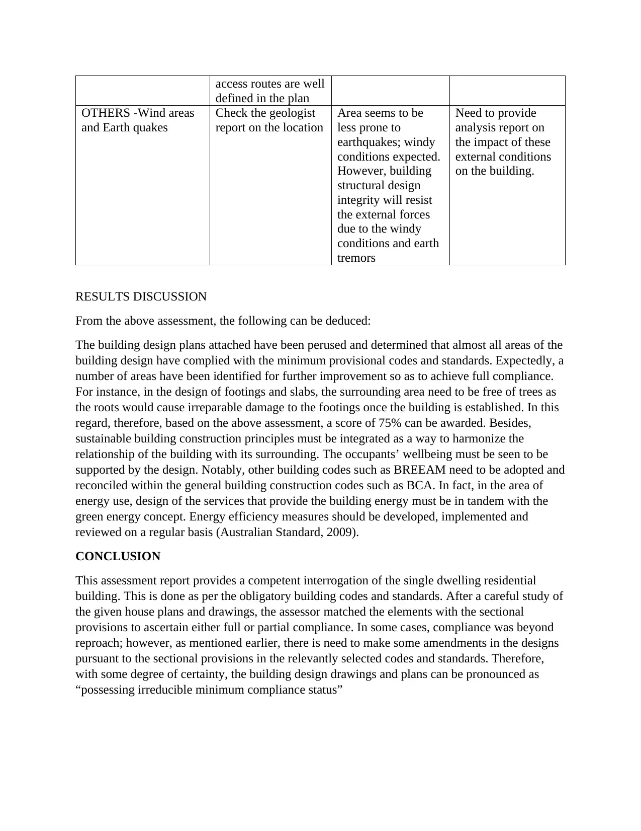
access routes are well
defined in the plan
OTHERS -Wind areas
and Earth quakes
Check the geologist
report on the location
Area seems to be
less prone to
earthquakes; windy
conditions expected.
However, building
structural design
integrity will resist
the external forces
due to the windy
conditions and earth
tremors
Need to provide
analysis report on
the impact of these
external conditions
on the building.
RESULTS DISCUSSION
From the above assessment, the following can be deduced:
The building design plans attached have been perused and determined that almost all areas of the
building design have complied with the minimum provisional codes and standards. Expectedly, a
number of areas have been identified for further improvement so as to achieve full compliance.
For instance, in the design of footings and slabs, the surrounding area need to be free of trees as
the roots would cause irreparable damage to the footings once the building is established. In this
regard, therefore, based on the above assessment, a score of 75% can be awarded. Besides,
sustainable building construction principles must be integrated as a way to harmonize the
relationship of the building with its surrounding. The occupants’ wellbeing must be seen to be
supported by the design. Notably, other building codes such as BREEAM need to be adopted and
reconciled within the general building construction codes such as BCA. In fact, in the area of
energy use, design of the services that provide the building energy must be in tandem with the
green energy concept. Energy efficiency measures should be developed, implemented and
reviewed on a regular basis (Australian Standard, 2009).
CONCLUSION
This assessment report provides a competent interrogation of the single dwelling residential
building. This is done as per the obligatory building codes and standards. After a careful study of
the given house plans and drawings, the assessor matched the elements with the sectional
provisions to ascertain either full or partial compliance. In some cases, compliance was beyond
reproach; however, as mentioned earlier, there is need to make some amendments in the designs
pursuant to the sectional provisions in the relevantly selected codes and standards. Therefore,
with some degree of certainty, the building design drawings and plans can be pronounced as
“possessing irreducible minimum compliance status”
Paraphrase This Document
Need a fresh take? Get an instant paraphrase of this document with our AI Paraphraser
REFERENCE
Australian Standard 3959. (2009). Construction of Buildings in Bushfire-prone areas. Council of
Standards.
BCA. (1996). Building Code of Australia. Council of Standards.
BCA. (1996). Building Code of Australia: Class 1 and Class 10 Buildings Housing Provisions.
Canbera AST.
Blanchi, R & Leonard, J. (2008) Property Safety - judging structural safety. In ‘Community
Bushfire Safety’. (J. Handmer, eds) CSIRO Publishing, Melbourne
Cheney P & Sullivan A. (2008). Grassfires, fuel, weather and fire behaviour - second edition.
CSIRO Publishing Collingwood, Australia
Environmental Resources Management Australia (2000) Baldivis Tramway Reserve
Management Plan - Final Report for the City of Rockingham.
RFS. (2012). Plans and Spaces for bush fire Construction. Available at:
https://www.rfs.nsw.gov.au/__data/assets/pdf_file/0020/4691/Hunter-BFRMP.pdf
Standards Australia (2009) Australian Standard (AS 3959-2009) Construction of buildings in
bushfire-prone areas.
TAS. (2010). Bush Fire hazard management. Available at:
http://www.fire.tas.gov.au/userfiles/tym/file/131392_Building_for_Bushfires_web.pdf
TAS. (2017). Planning. Advisory Note 20 Guidance on the Code and how to determine Bushfire-
Prone Areas is available at: http://www.planning.tas.gov.au/library_and_
information/planning_advisory_notes
The Bushfire-Prone Areas Code Planning Directive No. 5. Available at:
http://www.planning.tas.gov.au
Website 2010. (http://www.bom.gov.au/climate/averages/tables/cw_009194.shtml)
Western Australian Planning Commission (WAPC), Department of Planning and Fire and
Emergency Services Authority of Western Australia (FESA) (2010) Planning for Bush Fire
Protection guidelines - edition 2. Published by WAPC & FESA
1 out of 8
Your All-in-One AI-Powered Toolkit for Academic Success.
+13062052269
info@desklib.com
Available 24*7 on WhatsApp / Email
![[object Object]](/_next/static/media/star-bottom.7253800d.svg)
Unlock your academic potential
Copyright © 2020–2026 A2Z Services. All Rights Reserved. Developed and managed by ZUCOL.