Civil Engineering: Slope Stability Analysis Homework Solution
VerifiedAdded on 2022/09/02
|5
|798
|15
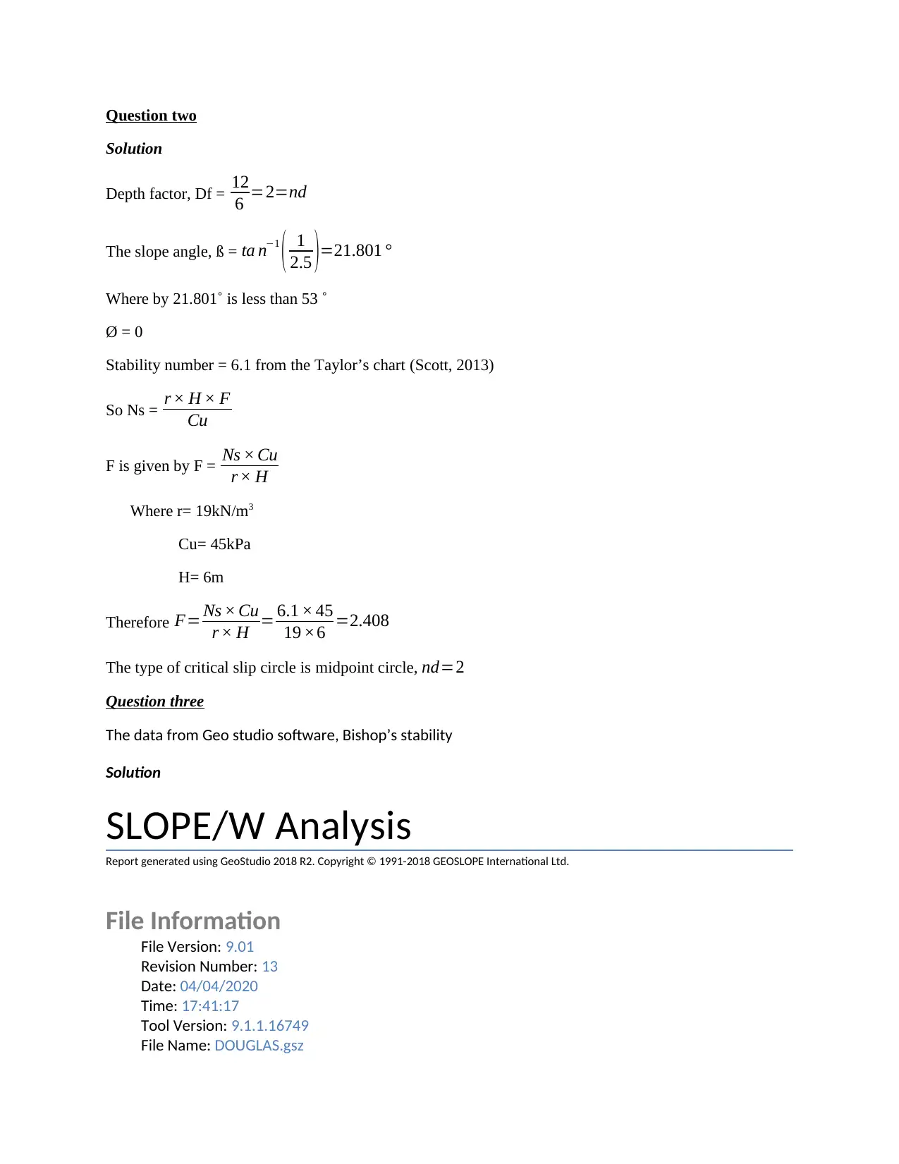
Homework Assignment
AI Summary
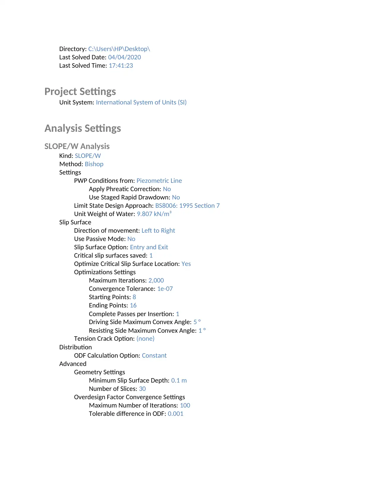
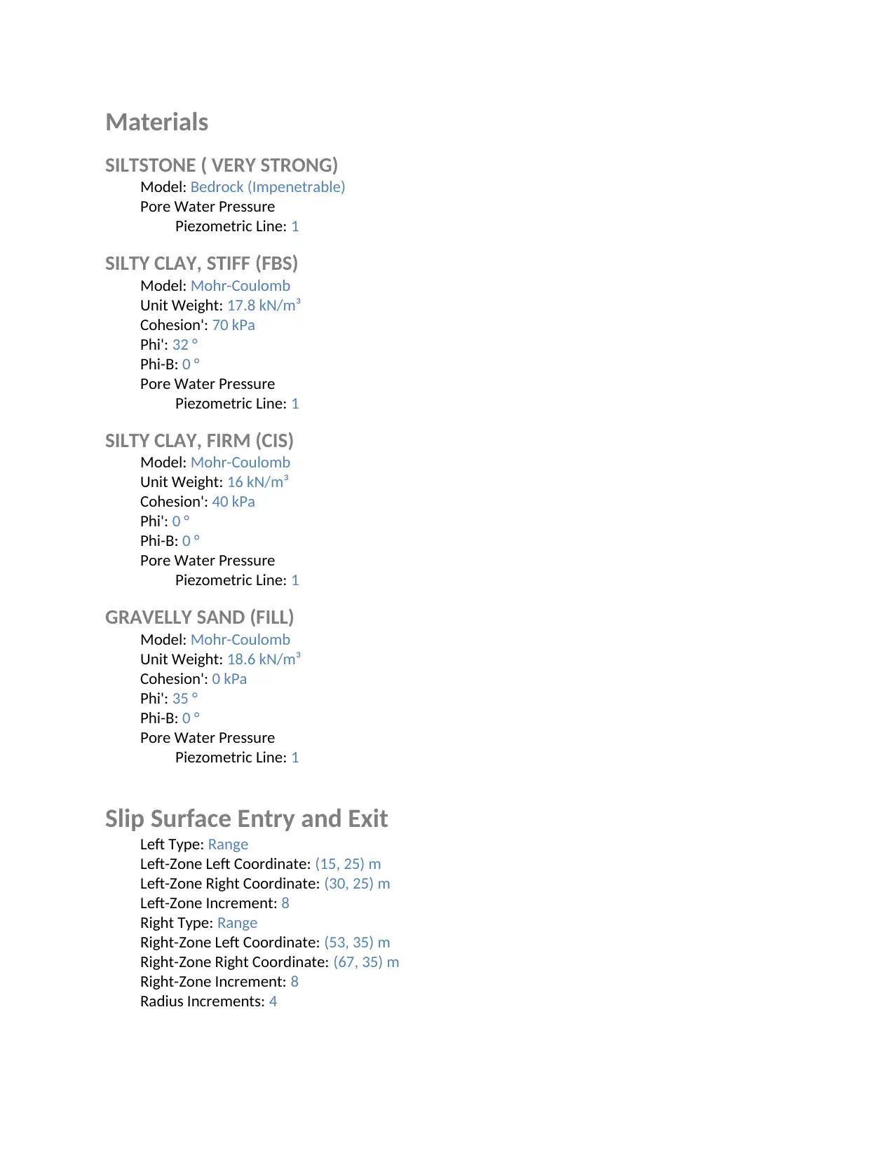
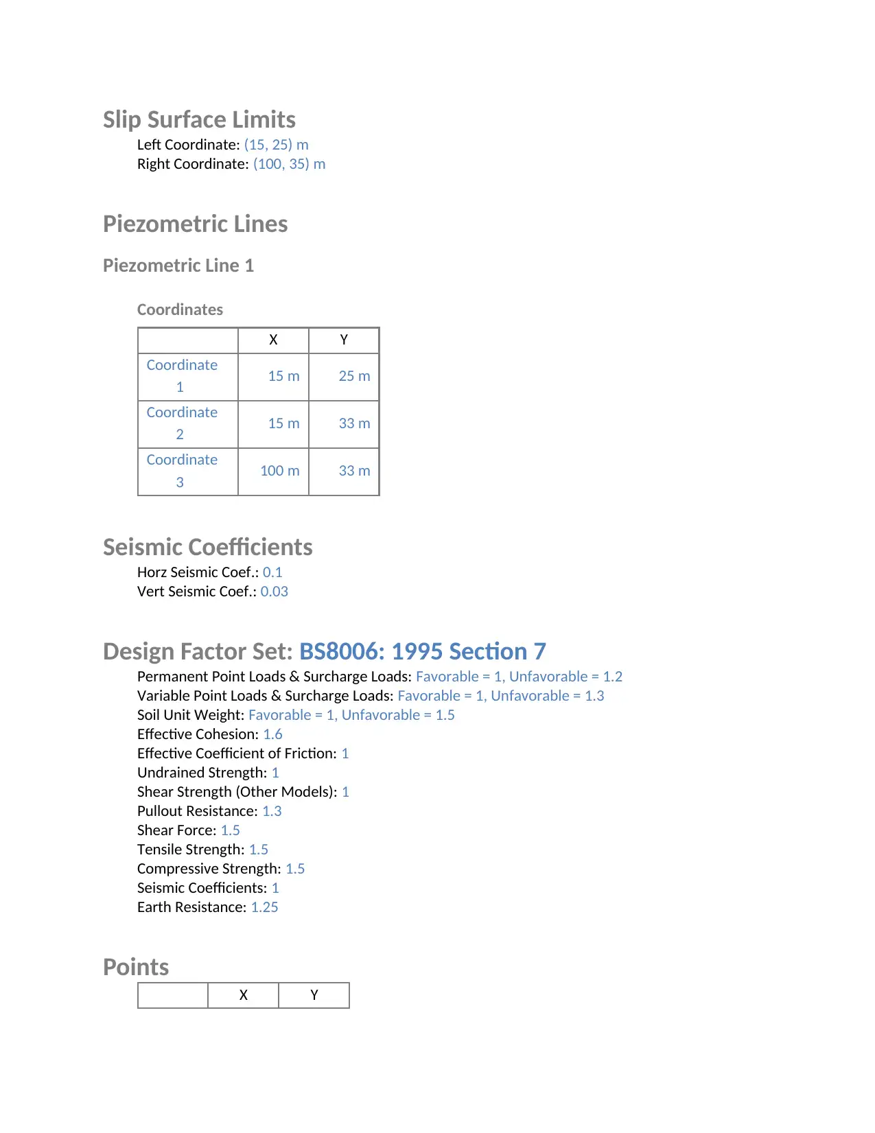
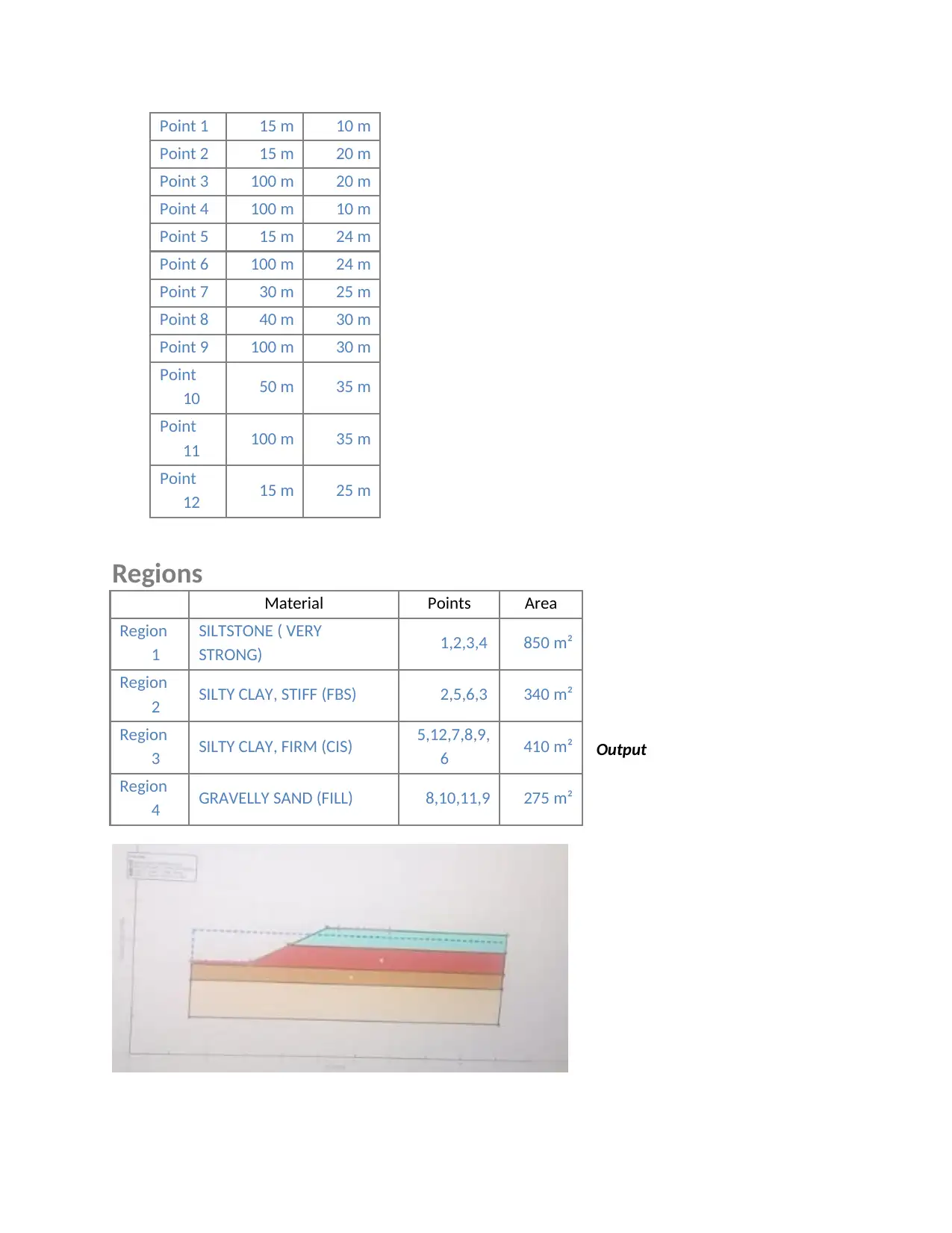
This document presents a solution to a civil engineering homework assignment focusing on slope stability analysis. The solution begins with calculations for the depth factor and stability number, referencing Taylor's chart to determine the type of critical slip circle. The core of the solution involves data extracted from GeoStudio software, specifically a SLOPE/W analysis report. This report details the project settings, including the unit system, analysis method (Bishop), material properties (SILTSTONE, SILTY CLAY, and GRAVELLY SAND), and slip surface parameters. The report also outlines the entry and exit points for slip surfaces, piezometric lines, seismic coefficients, and design factor settings. The document concludes with a reference to the source material, Scott's Principles of soil mechanics, providing a comprehensive overview of the slope stability analysis process.
1 out of 5
Your All-in-One AI-Powered Toolkit for Academic Success.
+13062052269
info@desklib.com
Available 24*7 on WhatsApp / Email
![[object Object]](/_next/static/media/star-bottom.7253800d.svg)
Copyright © 2020–2026 A2Z Services. All Rights Reserved. Developed and managed by ZUCOL.