Software Design Document (SDD) for the Botetlle Project in ISY3002
VerifiedAdded on 2023/01/11
|19
|3325
|81
Report
AI Summary
This Software Design Document (SDD) outlines the design for the Botetlle project, a system designed to collect and recycle containers, such as bottles, from individual houses. The SDD, adapted from IEEE STD 1016, details the project's purpose, scope, and overview, including references and definitions. The system overview describes the application's functionality, including user roles (Admin, Employee, User), login views, and features like order placement, transaction history, and rotational area management. The system architecture is divided into three parts: web-based user interfaces, application services, and a backend database. The architectural design is divided into three main parts: the web based API or user interfaces which contains the interface screens for doing the basic required functionalities of the system for their corresponding users, the application services that the system provides, and the backend system which comprises of the database which is used for storing users and transactions data. The decomposition description explains the functions of each user and subsystem, including sequence diagrams and object diagrams. The document also covers data design, component design, human interface design, and a requirements matrix, providing a comprehensive guide for software development and implementation. Diagrams are included to illustrate the system's components and data flow.
Software Design Document (SDD) Template (summarized from IEEE
STD 1016)
Software design is a process by which the software requirements are translated into
a representation of software components, interfaces, and data necessary for the
implementation phase.
The SDD shows how the software system will be structured to satisfy the
requirements.
It is the primary reference for code development and, therefore, it must contain all the
information required by a programmer to write code.
The SDD is performed in two stages. The first is a preliminary design in which the
overall system architecture and data architecture is defined. In the second stage, i.e.
the detailed design stage, more detailed data structures are defined and algorithms
are developed for the defined architecture.
This template is an annotated outline for a software design document adapted from
the IEEE Recommended Practice for Software Design Descriptions.
You can refer to IEEE Std 1016 2009 (first version 1998) ) for the full IEEE
Recommended Practice for Software Design Descriptions.
Paraphrase This Document
Need a fresh take? Get an instant paraphrase of this document with our AI Paraphraser
(Team Name)
(Project Title)
Software Design Document
Name (s):
Lab Section:
Workstation:
Date: (mm/dd/yyyy)
(Project Title)
Software Design Document
Name (s):
Lab Section:
Workstation:
Date: (mm/dd/yyyy)

TABLE OF CONTENTS
1. INTRODUCTION
1.1 Purpose
1.2 Scope
1.3 Overview
1.4 Reference Material
1.5 Definitions and Acronyms
2. SYSTEM OVERVIEW
3. SYSTEM ARCHITECTURE
3.1 Architectural Design
3.2 Decomposition Description
3.3 Design Rationale
4. DATA DESIGN
4.1 Data Description
4.2 Data Dictionary
5. COMPONENT DESIGN
6. HUMAN INTERFACE DESIGN
6.1 Overview of User Interface
6.2 Screen Images
6.3 Screen Objects and Actions
7. REQUIREMENTS MATRIX
8. APPENDICES
⊘ This is a preview!⊘
Do you want full access?
Subscribe today to unlock all pages.
Trusted by 1+ million students worldwide
1. INTRODUCTION
1.1 Purpose
This particular software design document (SDD) has been designed for Botetlle
which a design system needed for taking away all the containers from different
houses. The given bottles are taken to the reusing organization (Adams et al. 2015).
Australia is expanding to around 1.36 million tons of glass that are bundling on every
year basis. Human makes use of one million plastics which can suppress the moment
and most of end in landfill or even seas. There is large number of drink holders which
can easily hold volume of given volume for litter in NSW. An individual can get around
10 penny for every given jug for on the chance.
1.2 Scope
Despite immense quality of waste for business people and application of NSW that is
return and gain.
To place order for picking up bottle and related recycling item like second hand
that is used furniture.
User can earn money by choosing call immediate option and visiting the
rotational way.
To receive orders from customers so that they can pick bottle or recycling item
for second-hand use furniture (Devadiga 2017). It is mainly done so that they
can get offer.
To view all the history of transaction.
To have a rotational turn of the area along with notification 3-4 days on earlier
basis.
1.3 Overview
With the passage of every year, Australia is expanding around 1.36 million tons of
glass on every year basis. Human makes use of one million plastics so that they can
suppress the moment. Most of the given thing end up in sea or landfilling. The whole
thing starts up with an emergency that has a specialist state. There are many drink
holders which take up a major volume of litter in whole NSW.
Botetlle is such a design system which will take away the used containers from the
individual house for reusing organization. Individual can easily get around 10 penny
for every given jug that has an off chance for the place bottle in the container (Gaede
2016). In the given product, individual come up with the season of pick up for the
container right from their home. It can easily get jug so that they can get rubbish
receptacle free of jug. In the given product, they will merely get revolution plan mode
by the help of which goals and general population circumvent the home in the span of
fortnight.
Paraphrase This Document
Need a fresh take? Get an instant paraphrase of this document with our AI Paraphraser
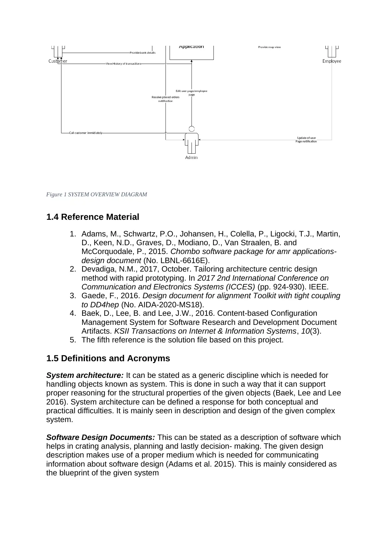
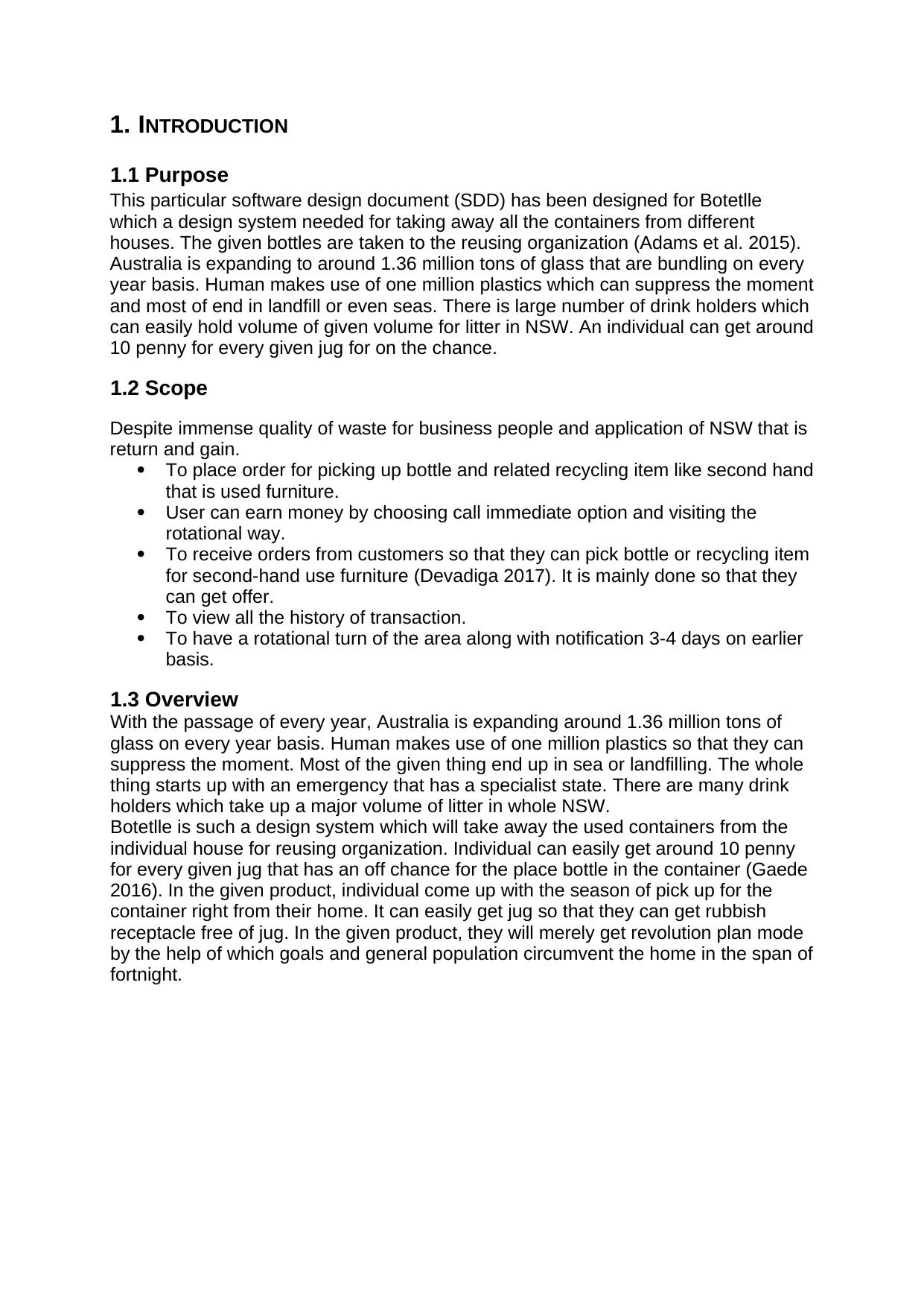
Figure 1 SYSTEM OVERVIEW DIAGRAM
1.4 Reference Material
1. Adams, M., Schwartz, P.O., Johansen, H., Colella, P., Ligocki, T.J., Martin,
D., Keen, N.D., Graves, D., Modiano, D., Van Straalen, B. and
McCorquodale, P., 2015. Chombo software package for amr applications-
design document (No. LBNL-6616E).
2. Devadiga, N.M., 2017, October. Tailoring architecture centric design
method with rapid prototyping. In 2017 2nd International Conference on
Communication and Electronics Systems (ICCES) (pp. 924-930). IEEE.
3. Gaede, F., 2016. Design document for alignment Toolkit with tight coupling
to DD4hep (No. AIDA-2020-MS18).
4. Baek, D., Lee, B. and Lee, J.W., 2016. Content-based Configuration
Management System for Software Research and Development Document
Artifacts. KSII Transactions on Internet & Information Systems, 10(3).
5. The fifth reference is the solution file based on this project.
1.5 Definitions and Acronyms
System architecture: It can be stated as a generic discipline which is needed for
handling objects known as system. This is done in such a way that it can support
proper reasoning for the structural properties of the given objects (Baek, Lee and Lee
2016). System architecture can be defined a response for both conceptual and
practical difficulties. It is mainly seen in description and design of the given complex
system.
Software Design Documents: This can be stated as a description of software which
helps in crating analysis, planning and lastly decision- making. The given design
description makes use of a proper medium which is needed for communicating
information about software design (Adams et al. 2015). This is mainly considered as
the blueprint of the given system

2. SYSTEM OVERVIEW
System development can be stated as the method defining the given process, testing
and lastly implementation of new program or software application. It is merely
inclusive of internal development for the given system, building database. The design
application comes up with three kinds of login views that are Admin, Employee and
User (Devadiga 2017). In this user will gain money for the given point when they want
to convert real money. There is a need for developing chat board in between client
and admin, employee.
User can easily place order for pickup of bottle and related another re-cycling
item for the given second used machine (Gaede 2016). In this user can earn
money either by making call or even visiting in rotational way.
Customer will place order for picking up bottle or recycling item like used
furniture and machines.
User can have the view of all the made transaction in the past.
The system will be designed in such a way they can get rotational turn of the
given area. It will provide an option for number of days they will receive the
notification.
Customer comes up with option of downloading required files from earlier
transaction in pdf format.
All the given transaction carried out by user will appear like virtual money into
their account. There comes up with the option of ‘Get my money for getting
real money’. A list of details is asked with respect to account name, account
number and lastly BSB number. As soon as the account number is verified, an
email is sent to the email address of the user (Baek, Lee and Lee 2016). An
individual can have their money within the time of 1-2 business days. In the
last, a message is displayed on the screen containing ‘Thank You for using our
service’. The required money is subtracted from the virtual account.
In the employee view requirement, user can have all the idea with respect to
users in a particular location.
In this system, user can update all the details so that they can keep track of
records.
It aims to provide a view or required GPS for tracking for mobile different
mobile application.
In the design system, admin can easily view requirements from various user
as soon as the order is placed. The mere function is going for immediate call
option.
Any kind of notification from the employees with respect to updating for the
user page.
The system comes up with dashboard that will provide all the collected
bottlenecks and points.
User can easily go the page of both employee and user along with option of
deleting user.
The design system comes up with four pin digit protection for getting access to
their account.
This is an online application where various users are synchronization
automatically.
The design system is completely robust, flexible and scalable in nature.
⊘ This is a preview!⊘
Do you want full access?
Subscribe today to unlock all pages.
Trusted by 1+ million students worldwide

3. SYSTEM ARCHITECTURE
3.1 Architectural Design
The main purpose of the application is to collect old, second hand unused objects like
furniture and bottles from the customers and then recycle them again for reuse. For
this service the customers will be able to earn points that can be converted to real
money. The application mainly takes the order from the user and then sends it to the
employees who process the order. The whole operation and the transaction business
is governed by the admin. The architecture of the system is divided into three main
parts. The first part consists of the web based API or user interfaces which contains
the interface screens for doing the basic required functionalities of the system for
their corresponding users. The login authentication part is common for all and is
managed by the mainframe controller using keys system. The user interface screen
for the admin, users and the employees differ from each other due to different
functionalities. The second part of the application deals with the application services
that the system provides. These services are divided into three parts which are the
customer or user part, the admin part and the employee part. The main service the
application provides to the user is the product ordering and payment receiving
services. The services provided to the admin is the display of system dashboard,
user accounts, employee accounts and deletion of user accounts. The services
provided to the employee are updating of user details, view users of a given area and
provide GPS tracking to users.
The third part of the architecture is the backend system which comprises of the
database which is used for storing users and transactions data. The mainframe
controller is used to handle most of the requests which includes processing of user
orders and their payments. The payment conversion and depositing into the bank
account of the user is handled by the dedicated payment system which may be an in-
house team or a third party vendor. The application is used by three main users
which are the admins, the employees and the customers.
Paraphrase This Document
Need a fresh take? Get an instant paraphrase of this document with our AI Paraphraser

Figure 2 ARCHITECTURE DESIGN DIAGRAM
3.2 Decomposition Description
The three main functions of the system can be classified under the three main users
of the system. For each user the system provides a fixed set of services. The overall
data flow of the system starts with the customer placing the user and ends with the
user receiving the money for the items he provided. The in between process is
handled by the admins and the employees who collect the items from the user and
then updates the corresponding payment details to the customer accounts. The
admin calls the user, gets the items picked up and processes the payment details
whereas the employees notifies the admins and updates the user details. Overall all
the three users work together to implement the system.
(SEE APPENDIX FOR DIAGRAMS)
The functions of each individual subsystem can be better understood by looking at
the sequence diagrams of the customer, admin and employee sub divisions. These
three major sub divisions are responsible for the proper functioning of the entire
system. The object diagram provided describes the main objects of the given system
and the functions or services related to them. It is a comprehensive model and is not
given in much detail for simplicity. The main functions of each of these subsystems
have already been discussed above. The system should show the customers their
transaction details or history. The structural composition models provided for each
subsystem includes the inputs, process and corresponding outputs. The diagrams
are given in detail and displays all the functions of the subsystem.
The sequence diagrams are also provided for a better understanding of the process
that is followed in the system and the flow of commands or information form one
entity to another entity. These sequence diagrams use objects and different type of
arrows to show the forward and reverse flow of information and activities.
3.3 Design Rationale
The main idea behind selecting the mentioned architecture because the model given
above simplifies the complex architecture underlying the system. The database and
the mainframe computer are necessary for the working of the system. A mainframe
computer is equivalent to multiple normal computers due to its sheer computing
power. The database is used to store the data generated from the customers and
their account information. The database is also used to store and retrieve orders that
the customers have placed.
⊘ This is a preview!⊘
Do you want full access?
Subscribe today to unlock all pages.
Trusted by 1+ million students worldwide
The main trade-offs in the given system is that the applications of the system are
limited in the given model of system architecture. Due to the limited nature of the
architecture model it is not possible to add extra functionalities to the system. Also
the architecture is designed in such a way that its database and backend hardware
can only support limited users and staff for management. As the service is online or
web based, the bandwidth is also another big issue for the given architecture.
Overall, considering everything it can be said that due to the small nature of the
application that is being developed the given architecture would be more than enough
to satisfy its functional as well as non-functional requirements.
4. DATA DESIGN
4.1 Data Description
The information that is being entered into the system by the users and the employees
are being stored in the form of data structures in the database that is pre-installed as
a part of the backend system. The conversion of the data into data structures are
being done by pre written scripts which can convert the entered data, classify them
into segments as per their user information and store them into the computer
controlled database for easy retrieval later. The classification of the data into different
data types or structures can help later during data retrieval.
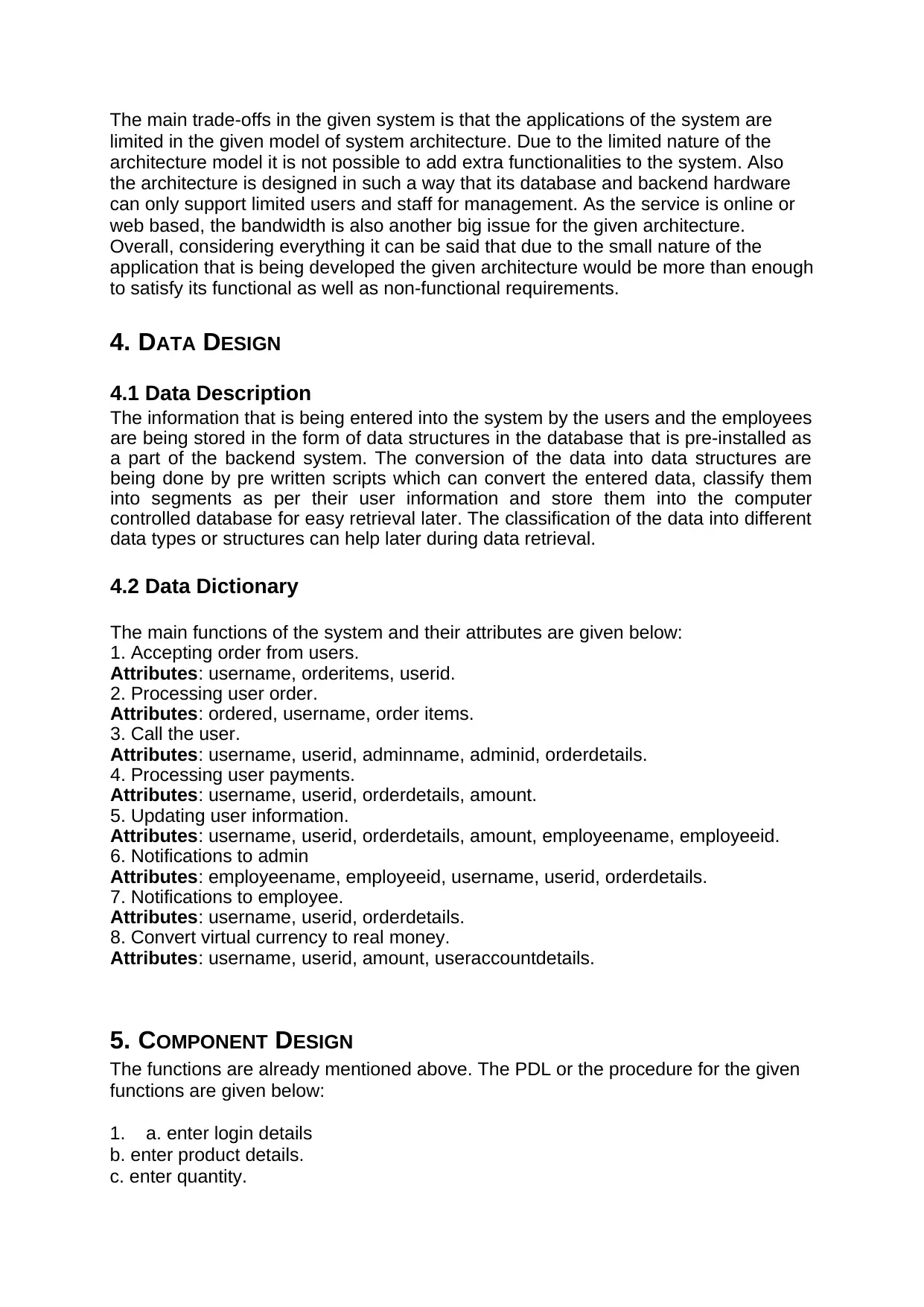
4.2 Data Dictionary
The main functions of the system and their attributes are given below:
1. Accepting order from users.
Attributes: username, orderitems, userid.
2. Processing user order.
Attributes: ordered, username, order items.
3. Call the user.
Attributes: username, userid, adminname, adminid, orderdetails.
4. Processing user payments.
Attributes: username, userid, orderdetails, amount.
5. Updating user information.
Attributes: username, userid, orderdetails, amount, employeename, employeeid.
6. Notifications to admin
Attributes: employeename, employeeid, username, userid, orderdetails.
7. Notifications to employee.
Attributes: username, userid, orderdetails.
8. Convert virtual currency to real money.
Attributes: username, userid, amount, useraccountdetails.
5. COMPONENT DESIGN
The functions are already mentioned above. The PDL or the procedure for the given
functions are given below:
1. a. enter login details
b. enter product details.
c. enter quantity.
limited in the given model of system architecture. Due to the limited nature of the
architecture model it is not possible to add extra functionalities to the system. Also
the architecture is designed in such a way that its database and backend hardware
can only support limited users and staff for management. As the service is online or
web based, the bandwidth is also another big issue for the given architecture.
Overall, considering everything it can be said that due to the small nature of the
application that is being developed the given architecture would be more than enough
to satisfy its functional as well as non-functional requirements.
4. DATA DESIGN
4.1 Data Description
The information that is being entered into the system by the users and the employees
are being stored in the form of data structures in the database that is pre-installed as
a part of the backend system. The conversion of the data into data structures are
being done by pre written scripts which can convert the entered data, classify them
into segments as per their user information and store them into the computer
controlled database for easy retrieval later. The classification of the data into different
data types or structures can help later during data retrieval.
4.2 Data Dictionary
The main functions of the system and their attributes are given below:
1. Accepting order from users.
Attributes: username, orderitems, userid.
2. Processing user order.
Attributes: ordered, username, order items.
3. Call the user.
Attributes: username, userid, adminname, adminid, orderdetails.
4. Processing user payments.
Attributes: username, userid, orderdetails, amount.
5. Updating user information.
Attributes: username, userid, orderdetails, amount, employeename, employeeid.
6. Notifications to admin
Attributes: employeename, employeeid, username, userid, orderdetails.
7. Notifications to employee.
Attributes: username, userid, orderdetails.
8. Convert virtual currency to real money.
Attributes: username, userid, amount, useraccountdetails.
5. COMPONENT DESIGN
The functions are already mentioned above. The PDL or the procedure for the given
functions are given below:
1. a. enter login details
b. enter product details.
c. enter quantity.
Paraphrase This Document
Need a fresh take? Get an instant paraphrase of this document with our AI Paraphraser

d Submit order.
2. a. enter login details.
b. view user order.
c. accept the order.
d. call the user.
3. a. view user order
b. call the user immediately
c. arrange order pickup
4. a. view order details.
b. pick up order.
c. process the payment.
d. proceed according to rate chart.
e. submit total amount
f. transfer equivalent virtual currency in user account.
5. a. view user information
b. edit user information
c. update new information
d. user information updated.
6. a. submit order.
b. send auto notification to employee.
c. process the order.
7. a. process the order.
b. notify the admin.
c. process user payment.
8. a. process the payment
b. add virtual currency to account.
c. input user bank account details.
d. submit equivalent real money into the bank account.
e. end
6. HUMAN INTERFACE DESIGN
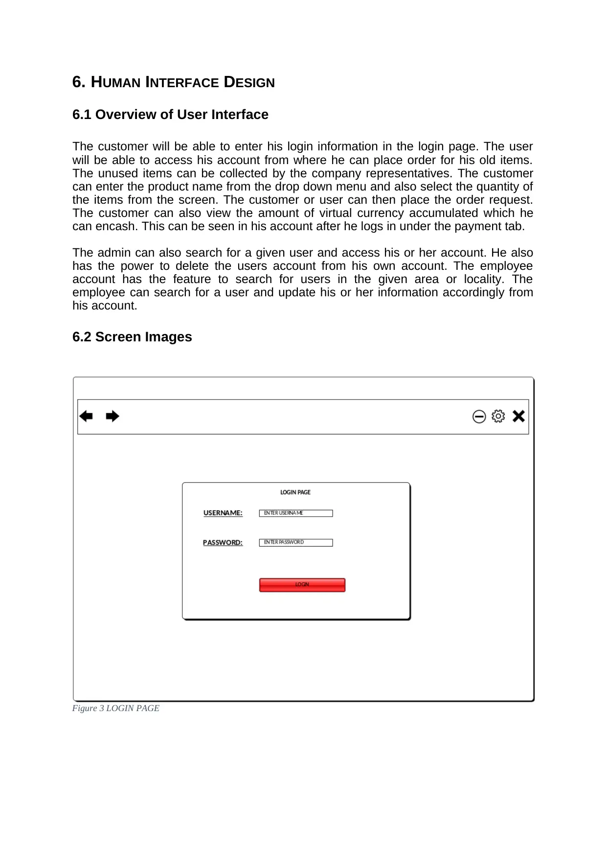
6.1 Overview of User Interface
The customer will be able to enter his login information in the login page. The user
will be able to access his account from where he can place order for his old items.
The unused items can be collected by the company representatives. The customer
can enter the product name from the drop down menu and also select the quantity of
the items from the screen. The customer or user can then place the order request.
The customer can also view the amount of virtual currency accumulated which he
can encash. This can be seen in his account after he logs in under the payment tab.
The admin can also search for a given user and access his or her account. He also
has the power to delete the users account from his own account. The employee
account has the feature to search for users in the given area or locality. The
employee can search for a user and update his or her information accordingly from
his account.
6.2 Screen Images
Figure 3 LOGIN PAGE
⊘ This is a preview!⊘
Do you want full access?
Subscribe today to unlock all pages.
Trusted by 1+ million students worldwide
1 out of 19
Your All-in-One AI-Powered Toolkit for Academic Success.
+13062052269
info@desklib.com
Available 24*7 on WhatsApp / Email
![[object Object]](/_next/static/media/star-bottom.7253800d.svg)
Unlock your academic potential
Copyright © 2020–2026 A2Z Services. All Rights Reserved. Developed and managed by ZUCOL.