Creating an ATM State Machine Diagram: A Software Engineering Project

Verified

Added on  2022/08/12

|8
|1695
|14
Project
AI Summary
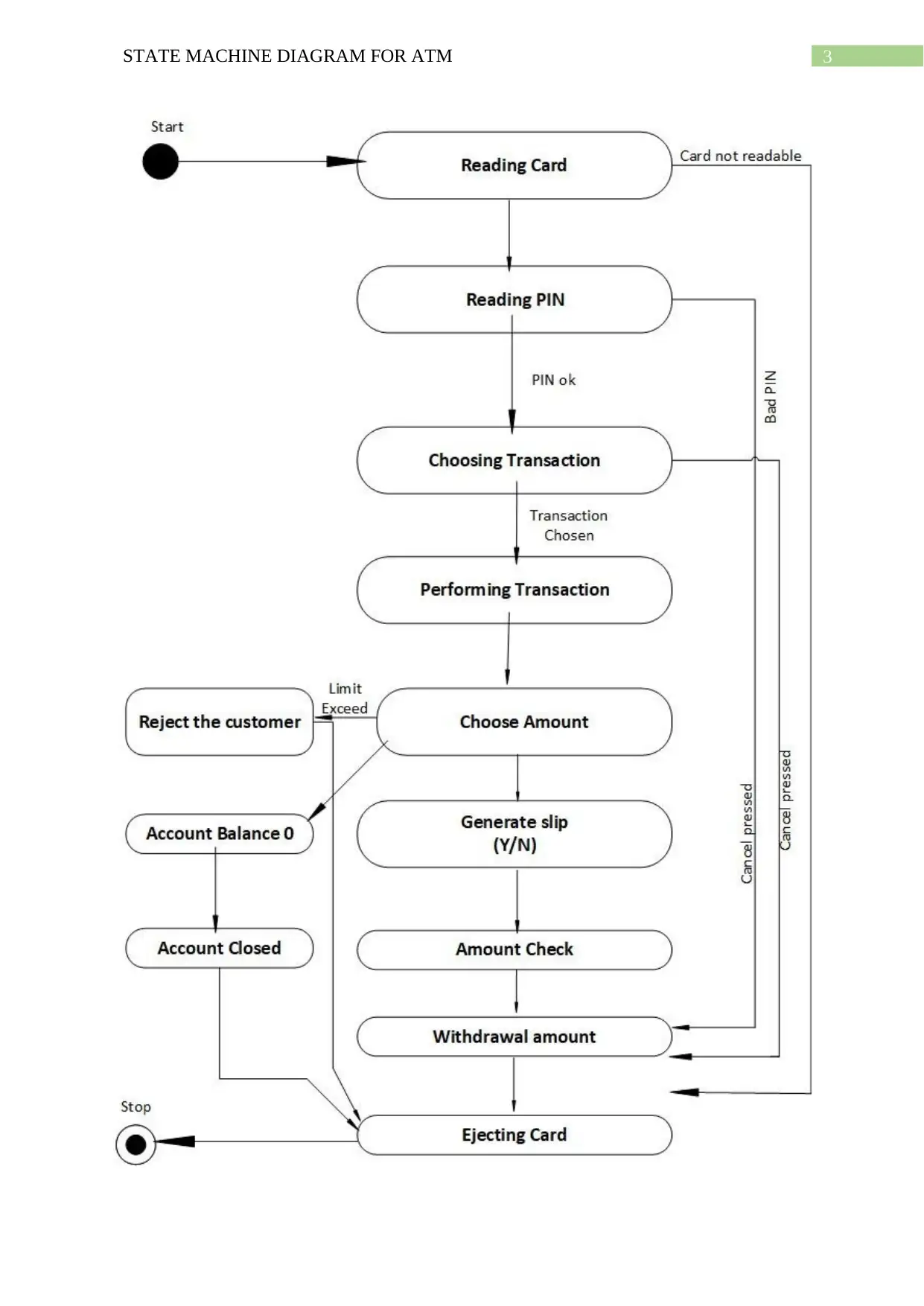
This project details the creation of a UML state machine diagram for an Automated Teller Machine (ATM). The assignment begins by defining the purpose and application of state machine diagrams, emphasizing their role in modeling system behavior and object states. The core of the project involves designing an ATM state machine diagram using Microsoft Visio, illustrating the ATM's operational flow from card reading to transaction completion and card ejection. The diagram encompasses various states, including card readability, PIN verification (with error handling), transaction selection, amount withdrawal (with limit checks), and printing options. The assignment also identifies the classes and attributes involved, such as Bank, ATM, Customer, Debit Card, and various transaction types. The state machine diagram effectively visualizes the ATM's processes, providing a clear understanding of how an ATM functions and how developers can use the diagram for design and coding. The project concludes by highlighting the diagram's utility in identifying potential errors, facilitating software updates, and serving as a foundational blueprint for ATM development.
Document Page
Running head: STATE MACHINE DIAGRAM FOR ATM
STATE MACHINE DIAGRAM FOR ATM
Student
Course
Instructor
Date
tabler-icon-diamond-filled.svg

Paraphrase This Document

Need a fresh take? Get an instant paraphrase of this document with our AI Paraphraser
Document Page
2STATE MACHINE DIAGRAM FOR ATM
STATE MACHINE DIAGRAM FOR ATM
State machine diagram is mostly used to define the state and the behaviour of a
system. The history of any entity can be modelled by the finite state machine diagram or also
called automata (El Miloudi & Ettouhami, 2015). The state machine diagram displays
different states of the object. It can similarly show how any object reacts to several events by
altering from one state to another. It is the UML diagram that is used to model the dynamic
nature of any system (Knapp et al., 2015). It is mainly used to describe the behaviour of the
state dependency for any object.
As a result, these diagrams are primarily applied to most of the objects. Still, it can also be
applied to other elements which have the behaviour to different objects like use cases,
methods, actors, subsystems systems and many more.
For this project, the creation of the state machine diagram for the automated teller
machine (ATM) is observed. To draw the diagram, the Microsoft Visio is used. The process
of the ATM can easily define by this UML state machine diagram (Jena, Swain &
Mohapatra, 2014). In this project, the ATM machine acts differently to the same event.
Reading card function has different behaviours like when the card is not readable. If the card
is readable, it will ask for a pin. Reading pin function is also act differently. When the user
pin is matched ATM let the user perform the next step. In case if a user provides the wrong
pin, ATM machine will display a message and redirected to the home screen. In this ATM
machine, choose account function has a different state during the operation. As per the user
requirement, this function can choose an account and work accordingly. The state machine
diagram for this ATM is provided below:
Document Page
3STATE MACHINE DIAGRAM FOR ATM
Document Page
4STATE MACHINE DIAGRAM FOR ATM
Figure 1: UML State Machine Diagram for ATM
(Source: created by author)
In figure 1 above, the UML state machine diagram for the ATM defines the process of
this ATM by which it works (Khan, 2015). In this diagram, the first state is reading the card.
If customer ATM card is not readable at that time of transaction ATM machine will eject the
card from the machine. If the card is readable, this machine will ask for the user PIN. If a
customer gives a bad PIN or incorrect PIN, then the card is ejected from the machine. If the
consumer gives a right PIN, then the machine shows the option to choose the transaction.
Then the chosen transaction is performed. After this, the customer has to choose the amount
for withdrawal (Kreuz, Luchkova & Schultz, 2016). If the limit is exceeded, then the
customer is rejected and after that the card is evicted by this machine. If the account balance
is zero, then the account is closed, and the card is evicted by the machine. After providing the
amount, this machine will display “print slip” option. There are two options present, one is
yes, and one is no (Moquillaza et al., 2017). After choosing an options, this machine will ask
for customer confirmation. Then the cash is withdrawn from the machine, and the transaction
is completed, and the card is ejected from the machine.
The classes of the above figure 1 UML state machine diagram are Bank, ATM,
Customer, Debit Card, Account, ATM Transaction, Savings Account, Checking Account,
Withdrawal transaction and Transfer Transaction. The Bank class has the attributes named
code and address. The ATM class has the attributes named location and managed. Three
attributes are present in Customer class name, address and dob. The Debit Card class has the
attributes named cardNo and ownedBy. The Account class has the attributes named type also
owner. The ATM Transaction class has many attributes named transactionId, date and type.
The accountNo is only attribute in Savings Account class also in the checking Account class.
tabler-icon-diamond-filled.svg

Paraphrase This Document

Need a fresh take? Get an instant paraphrase of this document with our AI Paraphraser
Document Page
5STATE MACHINE DIAGRAM FOR ATM
The Withdrawal transaction class has the attribute named amount. The Transfer Transaction
class has the attribute named amount. Every bank customer owns an account and debit card.
Most of the bank maintain their ATM machines. A customer can withdrawal money by using
ATM machine. From the above information and attributes, the state machine diagram can
draw. This diagram shows the different state of an ATM machine. Every process of ATM can
be described in this diagram.
After creating a UML state machine diagram, a person can get simply an idea of how
an ATM can work and the work process from the very beginning state. This diagram start
with the reading the card function to the last state that is ejecting the card after completion of
all the transaction.
After utilizing the above class and their attributes, the UML state machine diagram
can draw. After completing this drawing, any developer can design the ATM machine
(Kreuz, Luchkova & Schultz, 2016). All the coding part is described to develop the ATM by
the following requirements that are showing in this state machine diagram. Every states of
this system has different characteristics that are performed at the certain period of time. The
state is sometimes related to the abstraction of the attribute values of the entity that can
satisfy some of the conditions. The entity alters the state of it not only as of the direct
consequence of present input, also it is dependent on some of the past history of the inputs of
it (Araki, Mizoguchi & Hatsugai, 2019). After completing this diagram, any developer can
identify the empty phase in this development process, if anything error was found during
analysis, then they can resolve those issue. When a software update is required, the developer
can easily add or remove a few features by adding extra class and objects. Before making any
changes, they developed an updated UML state diagram, and after completing this diagram,
they can implement the new feature in the existing machine by adding or modifying existing
codes.
Document Page
6STATE MACHINE DIAGRAM FOR ATM
Conclusion
Thus, it can be concluded that the state machine diagram is the most useful technique
during development. This report defines the process of a state machine diagram of an ATM
machine. In this diagram, every process from initial state to the end state are provided. From
reading a card to card ejection. This diagram also defines internal state like when the card is
not readable during a transaction, this machine will eject the card. Another important state is
PIN reading. If a customer provides incorrectly, then the card will automatically be ejected
from the machine. After getting a correct PIN, this machine promotes a user to perform the
next step. After completing this project, a reader can get an idea about the state diagram and
how it can be used to develop an ATM machine.
Document Page
7STATE MACHINE DIAGRAM FOR ATM
References
Araki, H., Mizoguchi, T., & Hatsugai, Y. (2019). Phase diagram of a disordered higher-order
topological insulator: A machine learning study. Physical Review B, 99(8), 085406.
El Miloudi, K. H. A. D. I. J. A., & Ettouhami, A. Z. I. Z. (2015). A Multi-view approach for
formalizing UML state machine diagrams using Z notation. WSEAS Transactions on
Computers, 14, 72-78.
Jena, A. K., Swain, S. K., & Mohapatra, D. P. (2014, February). A novel approach for test
case generation from UML activity diagram. In 2014 International Conference on
Issues and Challenges in Intelligent Computing Techniques (ICICT) (pp. 621-629).
IEEE.
Khan, M. U. (2015, January). Representing Security Specifications in UML State Machine
Diagrams. In FNC/MobiSPC (pp. 453-458).
Knapp, A., Mossakowski, T., Roggenbach, M., & Glauer, M. (2015, April). An institution for
simple UML state machines. In International Conference on Fundamental
Approaches to Software Engineering (pp. 3-18). Springer, Berlin, Heidelberg.
Kreuz, M., Luchkova, T., & Schultz, M. (2016, May). Effect of restricted airspace on the
ATM system. In Proceedings of the World Conference on Transport Research
(WCTR 2016), Shanghai, China (pp. 10-15).
Moquillaza, A., Molina, E., Noguera, E., Enríquez, L., Muñoz, A., Paz, F., & Collazos, C.
(2017, July). Developing an ATM interface using user-centered design techniques. In
International Conference of Design, User Experience, and Usability (pp. 690-701).
Springer, Cham.
tabler-icon-diamond-filled.svg

Paraphrase This Document

Need a fresh take? Get an instant paraphrase of this document with our AI Paraphraser
Document Page
8STATE MACHINE DIAGRAM FOR ATM
Walkinshaw, N., Taylor, R., & Derrick, J. (2016). Inferring extended finite state machine
models from software executions. Empirical Software Engineering, 21(3), 811-853.
chevron_up_icon
1 out of 8
circle_padding
hide_on_mobile
zoom_out_icon
[object Object]