MITS5002 Software Engineering: Sunshine Motors Design Report
VerifiedAdded on  2023/01/10
|17
|798
|40
Report
AI Summary
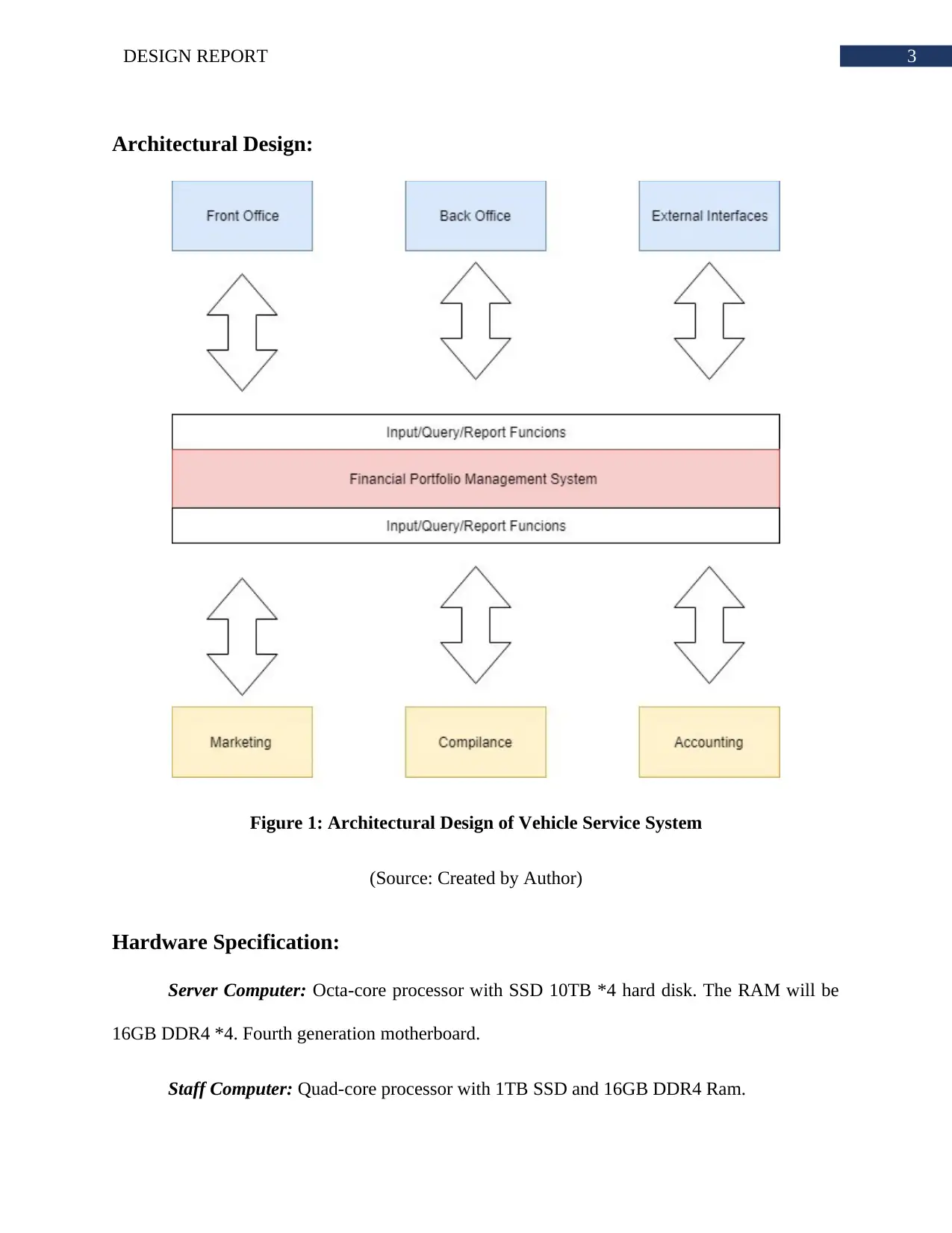
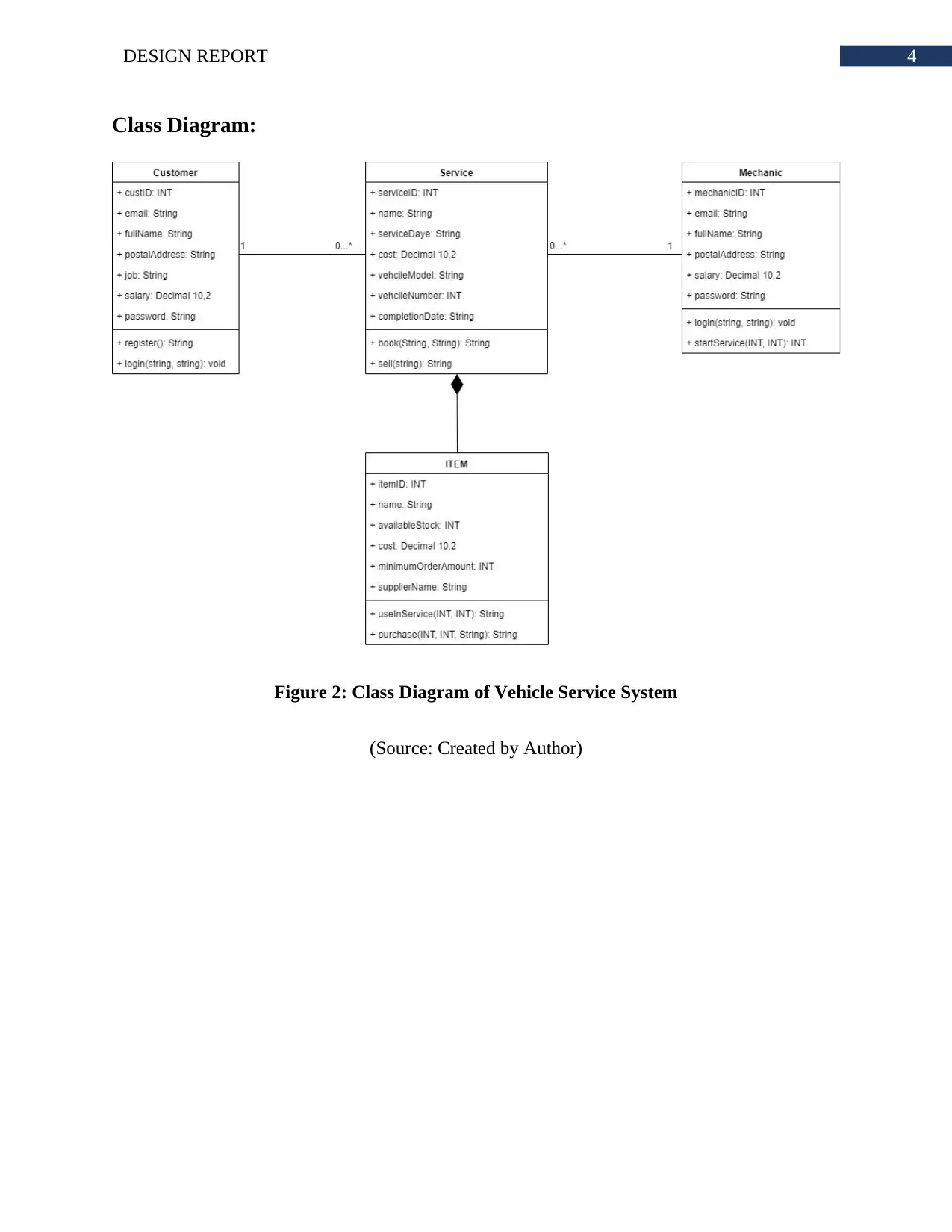
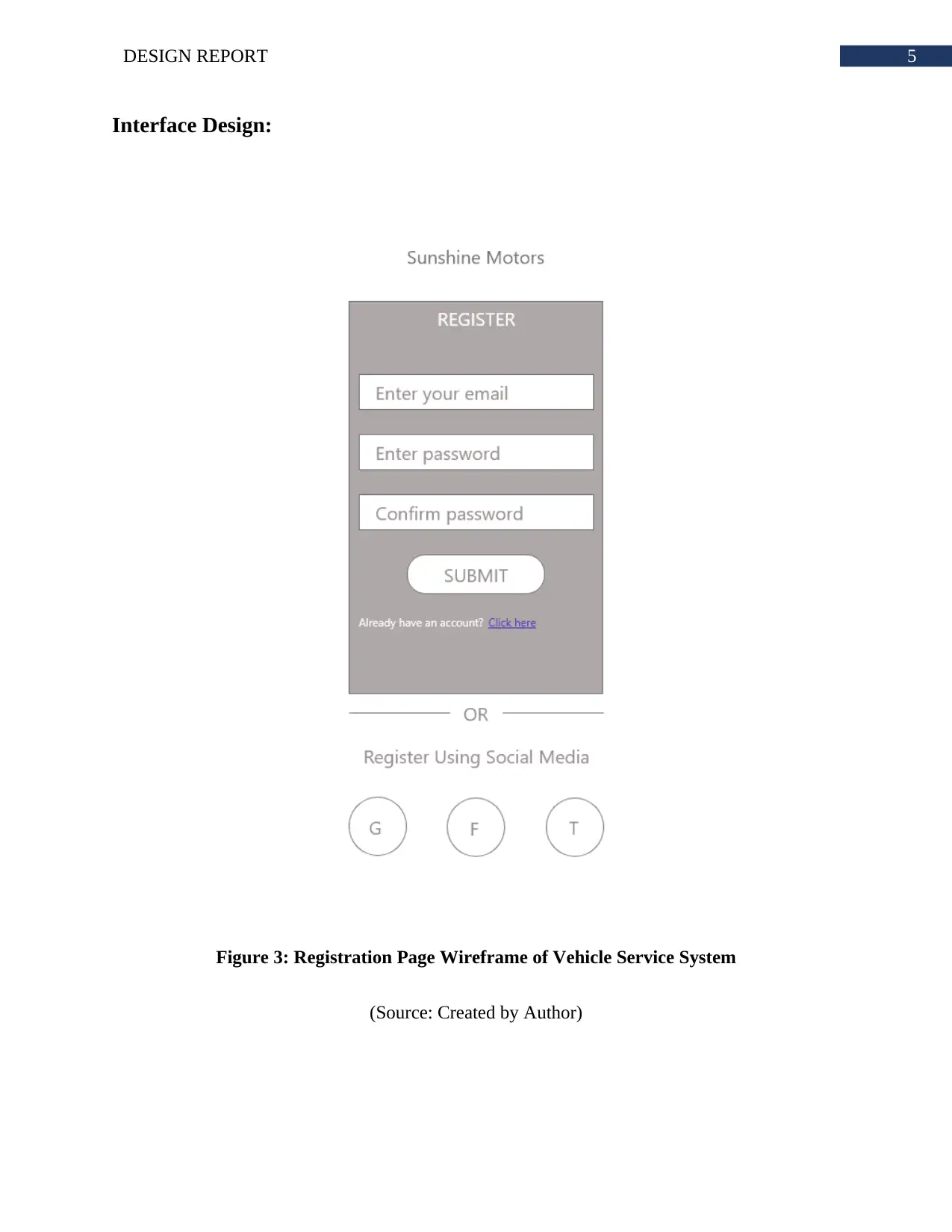
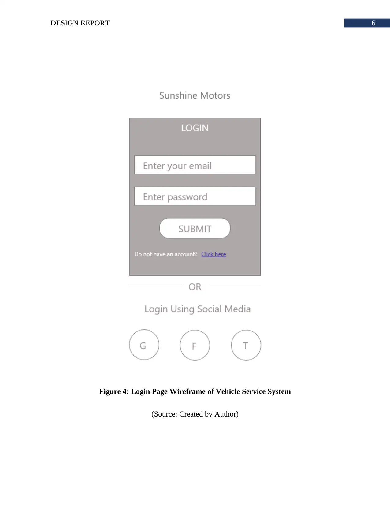
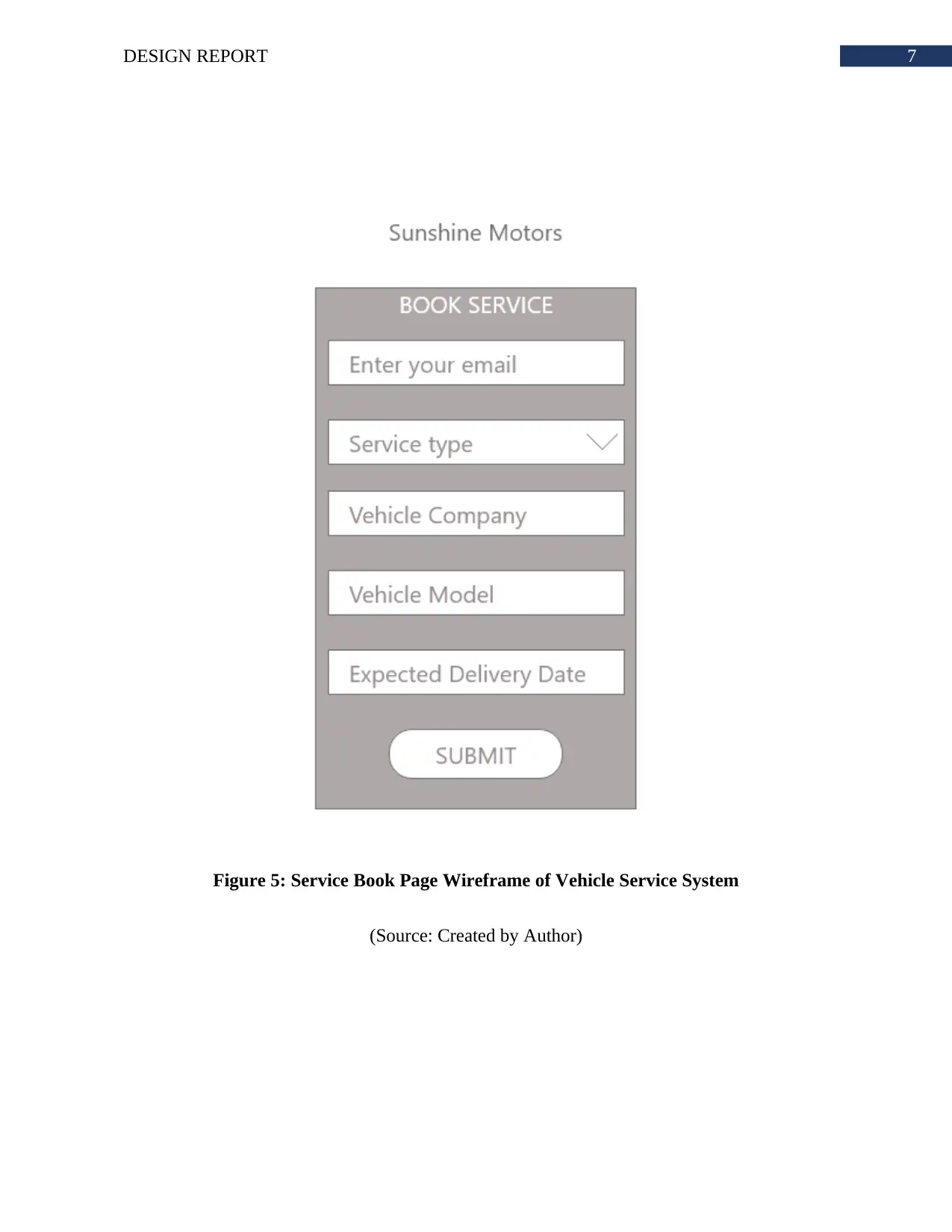
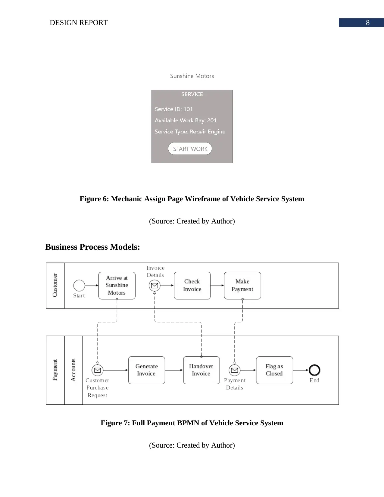
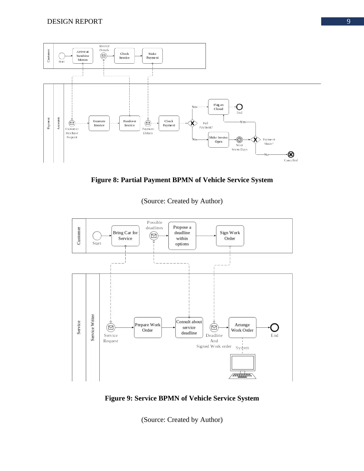
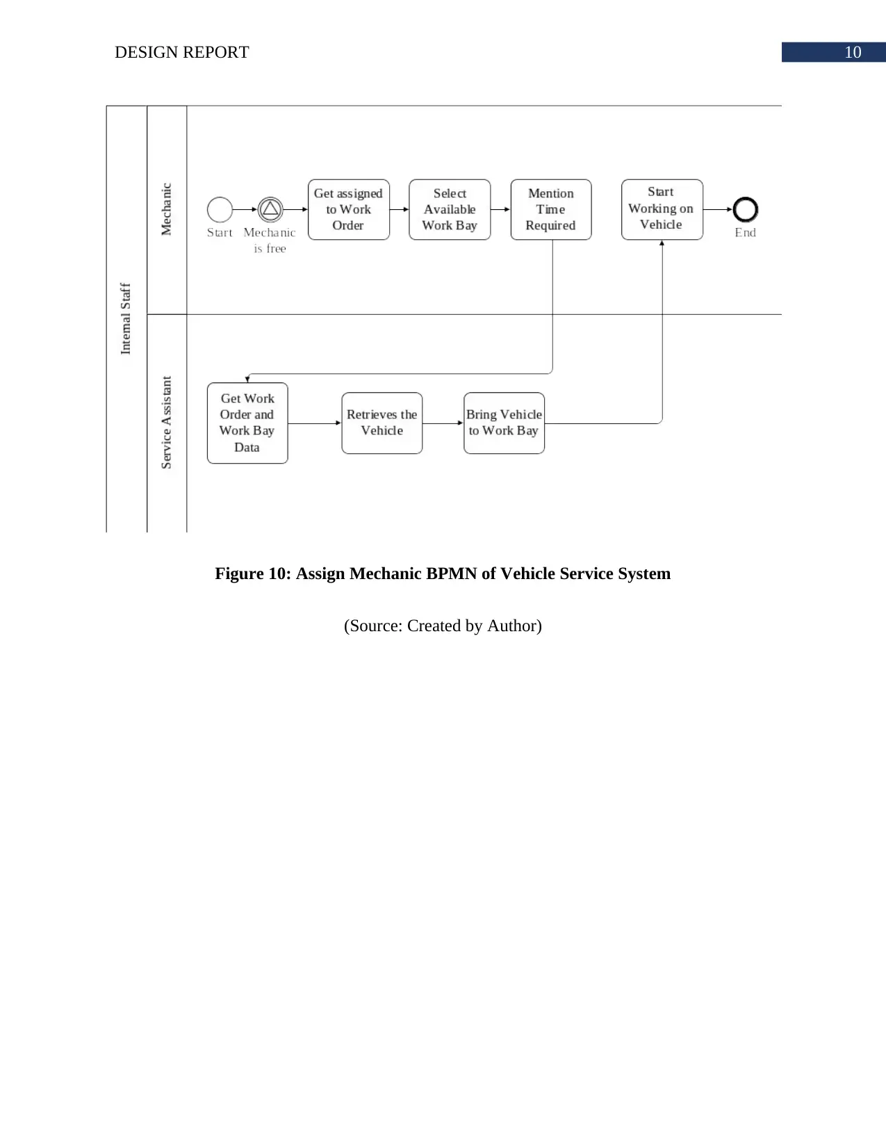
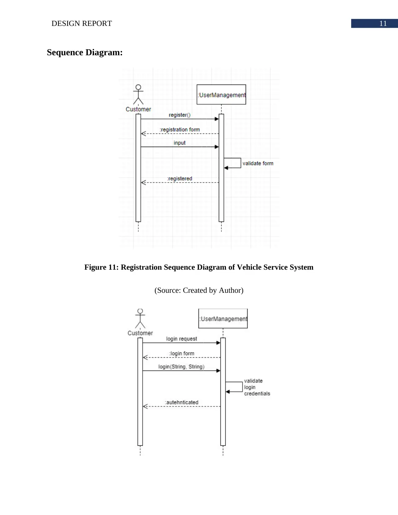
This design report details the system design for Sunshine Motors' vehicle service system, developed as part of a software engineering assignment. The report encompasses the architectural design, hardware specifications, class diagrams, interface designs (including registration, login, and service booking pages), and business process models. It also includes sequence diagrams illustrating registration, login, service booking, and mechanic service start processes, along with interaction and state diagrams for the same functionalities. The report concludes with a bibliography of relevant sources.

Running head: DESIGN REPORT
Design Report
Name of the Student
Name of the University
Author’s Note:
Design Report
Name of the Student
Name of the University
Author’s Note:
Paraphrase This Document
Need a fresh take? Get an instant paraphrase of this document with our AI Paraphraser

1DESIGN REPORT
Executive Summary
The report reflects the system design of Sunshine Motors. The report includes the architecture of
the system based on which the entire system will work. The system interface shows how the
input/output screen of the system. The UML diagrams shows both the static and dynamic nature
of the system.

2DESIGN REPORT
Table of Contents
Architectural Design:.......................................................................................................................3
Hardware Specification:..................................................................................................................3
Class Diagram:.................................................................................................................................4
Interface Design:..............................................................................................................................5
Business Process Models:................................................................................................................8
Sequence Diagram:........................................................................................................................11
Interaction Diagram:......................................................................................................................13
State Diagram:...............................................................................................................................14
Bibliography:.................................................................................................................................16
⊘ This is a preview!⊘
Do you want full access?
Subscribe today to unlock all pages.

Trusted by 1+ million students worldwide

3DESIGN REPORT
Architectural Design:
Figure 1: Architectural Design of Vehicle Service System
(Source: Created by Author)
Hardware Specification:
Server Computer: Octa-core processor with SSD 10TB *4 hard disk. The RAM will be
16GB DDR4 *4. Fourth generation motherboard.
Staff Computer: Quad-core processor with 1TB SSD and 16GB DDR4 Ram.
Paraphrase This Document
Need a fresh take? Get an instant paraphrase of this document with our AI Paraphraser

4DESIGN REPORT
Class Diagram:
Figure 2: Class Diagram of Vehicle Service System
(Source: Created by Author)
Class Diagram:
Figure 2: Class Diagram of Vehicle Service System
(Source: Created by Author)

5DESIGN REPORT
Interface Design:
Figure 3: Registration Page Wireframe of Vehicle Service System
(Source: Created by Author)
Interface Design:
Figure 3: Registration Page Wireframe of Vehicle Service System
(Source: Created by Author)
⊘ This is a preview!⊘
Do you want full access?
Subscribe today to unlock all pages.

Trusted by 1+ million students worldwide

6DESIGN REPORT
Figure 4: Login Page Wireframe of Vehicle Service System
(Source: Created by Author)
Figure 4: Login Page Wireframe of Vehicle Service System
(Source: Created by Author)
Paraphrase This Document
Need a fresh take? Get an instant paraphrase of this document with our AI Paraphraser

7DESIGN REPORT
Figure 5: Service Book Page Wireframe of Vehicle Service System
(Source: Created by Author)
Figure 5: Service Book Page Wireframe of Vehicle Service System
(Source: Created by Author)

8DESIGN REPORT
Figure 6: Mechanic Assign Page Wireframe of Vehicle Service System
(Source: Created by Author)
Business Process Models:
Figure 7: Full Payment BPMN of Vehicle Service System
(Source: Created by Author)
Figure 6: Mechanic Assign Page Wireframe of Vehicle Service System
(Source: Created by Author)
Business Process Models:
Figure 7: Full Payment BPMN of Vehicle Service System
(Source: Created by Author)
⊘ This is a preview!⊘
Do you want full access?
Subscribe today to unlock all pages.

Trusted by 1+ million students worldwide

9DESIGN REPORT
Figure 8: Partial Payment BPMN of Vehicle Service System
(Source: Created by Author)
Figure 9: Service BPMN of Vehicle Service System
(Source: Created by Author)
Figure 8: Partial Payment BPMN of Vehicle Service System
(Source: Created by Author)
Figure 9: Service BPMN of Vehicle Service System
(Source: Created by Author)
Paraphrase This Document
Need a fresh take? Get an instant paraphrase of this document with our AI Paraphraser

10DESIGN REPORT
Figure 10: Assign Mechanic BPMN of Vehicle Service System
(Source: Created by Author)
Figure 10: Assign Mechanic BPMN of Vehicle Service System
(Source: Created by Author)

11DESIGN REPORT
Sequence Diagram:
Figure 11: Registration Sequence Diagram of Vehicle Service System
(Source: Created by Author)
Sequence Diagram:
Figure 11: Registration Sequence Diagram of Vehicle Service System
(Source: Created by Author)
⊘ This is a preview!⊘
Do you want full access?
Subscribe today to unlock all pages.

Trusted by 1+ million students worldwide
1 out of 17
Related Documents

Your All-in-One AI-Powered Toolkit for Academic Success.
 +13062052269
info@desklib.com
Available 24*7 on WhatsApp / Email
Unlock your academic potential
Copyright © 2020–2025 A2Z Services. All Rights Reserved. Developed and managed by ZUCOL.