Software Engineering Project: SDLC, Design, and Evaluation Report
VerifiedAdded on 2023/01/13
|25
|6367
|99
Project
AI Summary
This project report, focused on the principles of software engineering, explores the importance of software development within an organization, using Hastings Dental Health Care as a case study. It details the Software Development Life Cycle (SDLC) and its methods, including use case models, class design, and sequence diagrams, while also addressing associated challenges. The report emphasizes the critical role of software development in organizational growth, covering aspects like encapsulation, abstraction, and inheritance in software design. The project includes a critical evaluation of the SDLC and software development challenges, concluding with the significance of software development for overall organizational advancement.

Module Title: Principles of Software Engineering
Words 4000
Coursework Title: Project
PRINCIPLES OF SOFTWARE ENGINEERING
1
Words 4000
Coursework Title: Project
PRINCIPLES OF SOFTWARE ENGINEERING
1
Paraphrase This Document
Need a fresh take? Get an instant paraphrase of this document with our AI Paraphraser
Executive Summary
This report is all about the principles of Software Engineering. Importance of software
development within an organization has been discussed here. An organization named as Hastings
dental health care has been taken into account and how this organization have used this newly
developed software for its betterment that has been described. Software development life cycle
along with all methods has been discussed and the challenges that need to be faced during a
software development, has been described. Finally, this report has been concluded that
importance of software development in an organization is very crucial for that overall
organizational development.
2
Table of Contents
Component 1: Software design and project prototype...................................................................4
Case model...................................................................................................................................4
Class design..................................................................................................................................4
Sequential diagram.....................................................................................................................10
Component 2: Critical-Evaluation.................................................................................................14
Introduction................................................................................................................................14
SDLC.........................................................................................................................................14
Software Development and its Challenges................................................................................18
Conclusion.....................................................................................................................................20
Reference list.................................................................................................................................21
3
⊘ This is a preview!⊘
Do you want full access?
Subscribe today to unlock all pages.
Trusted by 1+ million students worldwide
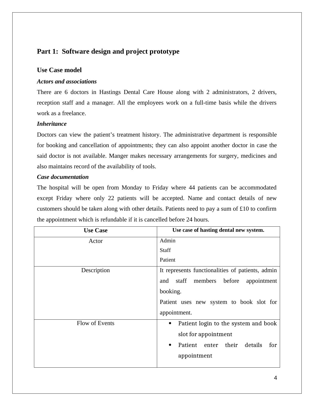
Part 1: Software design and project prototype
Use Case model
Actors and associations
There are 6 doctors in Hastings Dental Care House along with 2 administrators, 2 drivers,
reception staff and a manager. All the employees work on a full-time basis while the drivers
work as a freelance.
Inheritance
Doctors can view the patient’s treatment history. The administrative department is responsible
for booking and cancellation of appointments; they can also appoint another doctor in case the
said doctor is not available. Manger makes necessary arrangements for surgery, medicines and
also maintains record of the availability of tools.
Case documentation
The hospital will be open from Monday to Friday where 44 patients can be accommodated
except Friday where only 22 patients will be accepted. Name and contact details of new
customers should be taken along with other details. Patients need to pay a sum of £10 to confirm
the appointment which is refundable if it is cancelled before 24 hours.
Use Case Use case of hasting dental new system.
Actor Admin
Staff
Patient
Description It represents functionalities of patients, admin
and staff members before appointment
booking.
Patient uses new system to book slot for
appointment.
Flow of Events Patient login to the system and book
slot for appointment
Patient enter their details for
appointment
4
Paraphrase This Document
Need a fresh take? Get an instant paraphrase of this document with our AI Paraphraser
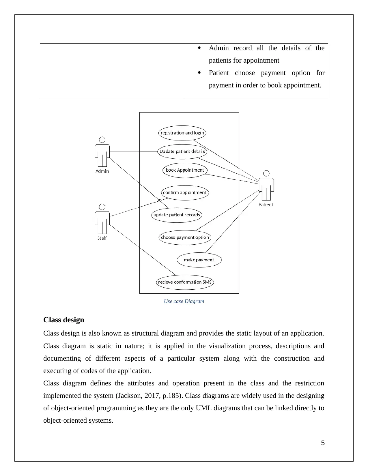
Admin record all the details of the
patients for appointment
Patient choose payment option for
payment in order to book appointment.
Use case Diagram
Class design
Class design is also known as structural diagram and provides the static layout of an application.
Class diagram is static in nature; it is applied in the visualization process, descriptions and
documenting of different aspects of a particular system along with the construction and
executing of codes of the application.
Class diagram defines the attributes and operation present in the class and the restriction
implemented the system (Jackson, 2017, p.185). Class diagrams are widely used in the designing
of object-oriented programming as they are the only UML diagrams that can be linked directly to
object-oriented systems.
5
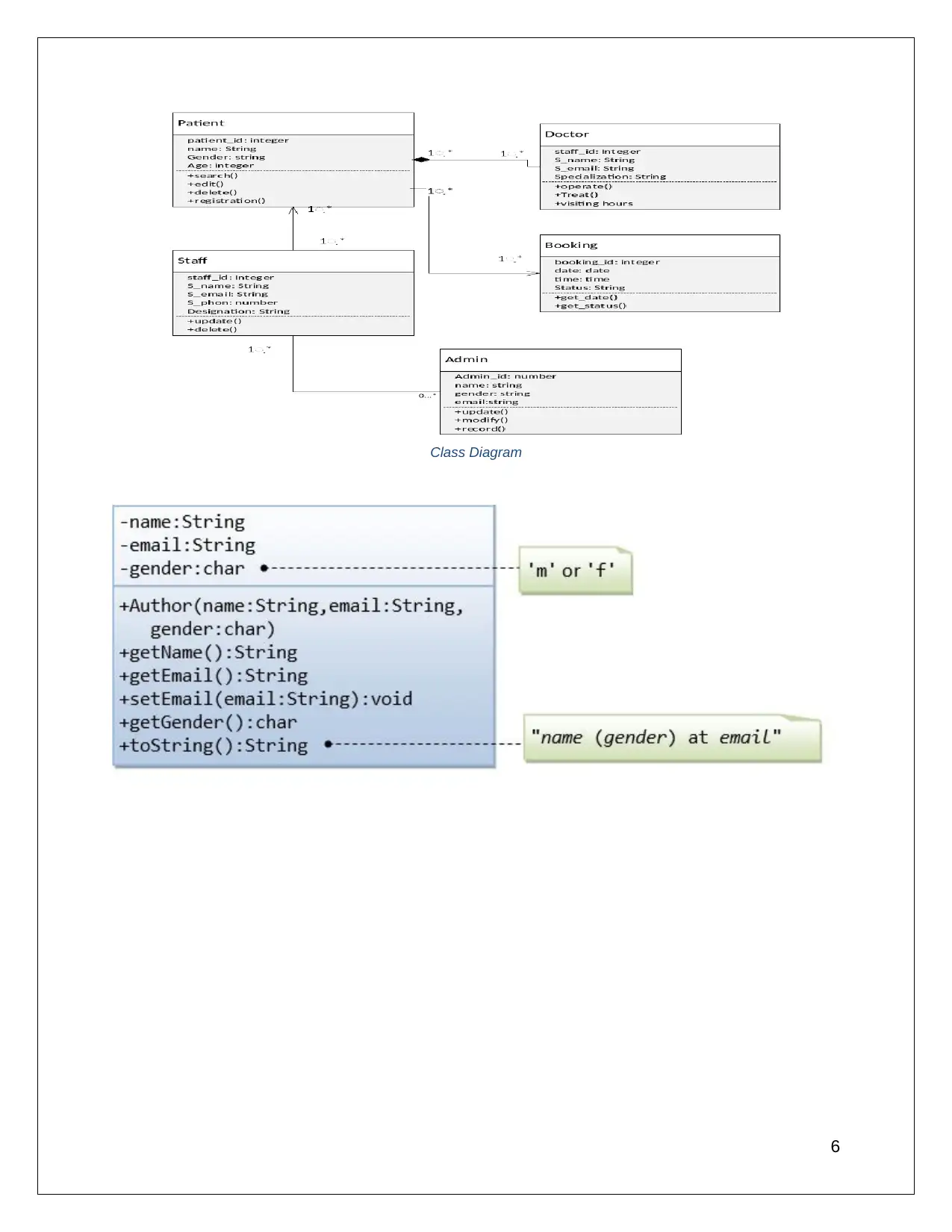
Class Diagram
6
6
⊘ This is a preview!⊘
Do you want full access?
Subscribe today to unlock all pages.
Trusted by 1+ million students worldwide
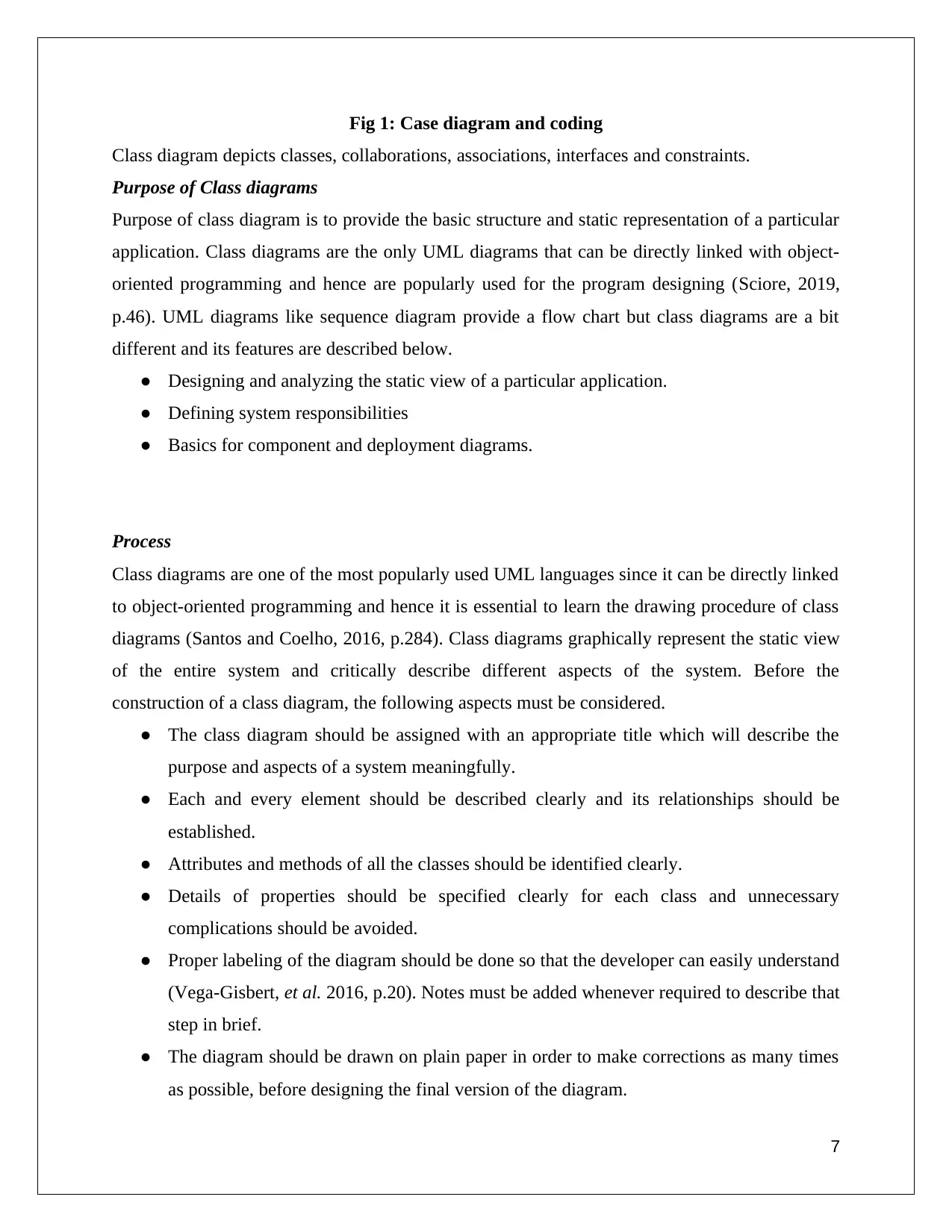
Fig 1: Case diagram and coding
Class diagram depicts classes, collaborations, associations, interfaces and constraints.
Purpose of Class diagrams
Purpose of class diagram is to provide the basic structure and static representation of a particular
application. Class diagrams are the only UML diagrams that can be directly linked with object-
oriented programming and hence are popularly used for the program designing (Sciore, 2019,
p.46). UML diagrams like sequence diagram provide a flow chart but class diagrams are a bit
different and its features are described below.
● Designing and analyzing the static view of a particular application.
● Defining system responsibilities
● Basics for component and deployment diagrams.
Process
Class diagrams are one of the most popularly used UML languages since it can be directly linked
to object-oriented programming and hence it is essential to learn the drawing procedure of class
diagrams (Santos and Coelho, 2016, p.284). Class diagrams graphically represent the static view
of the entire system and critically describe different aspects of the system. Before the
construction of a class diagram, the following aspects must be considered.
● The class diagram should be assigned with an appropriate title which will describe the
purpose and aspects of a system meaningfully.
● Each and every element should be described clearly and its relationships should be
established.
● Attributes and methods of all the classes should be identified clearly.
● Details of properties should be specified clearly for each class and unnecessary
complications should be avoided.
● Proper labeling of the diagram should be done so that the developer can easily understand
(Vega-Gisbert, et al. 2016, p.20). Notes must be added whenever required to describe that
step in brief.
● The diagram should be drawn on plain paper in order to make corrections as many times
as possible, before designing the final version of the diagram.
7
Paraphrase This Document
Need a fresh take? Get an instant paraphrase of this document with our AI Paraphraser
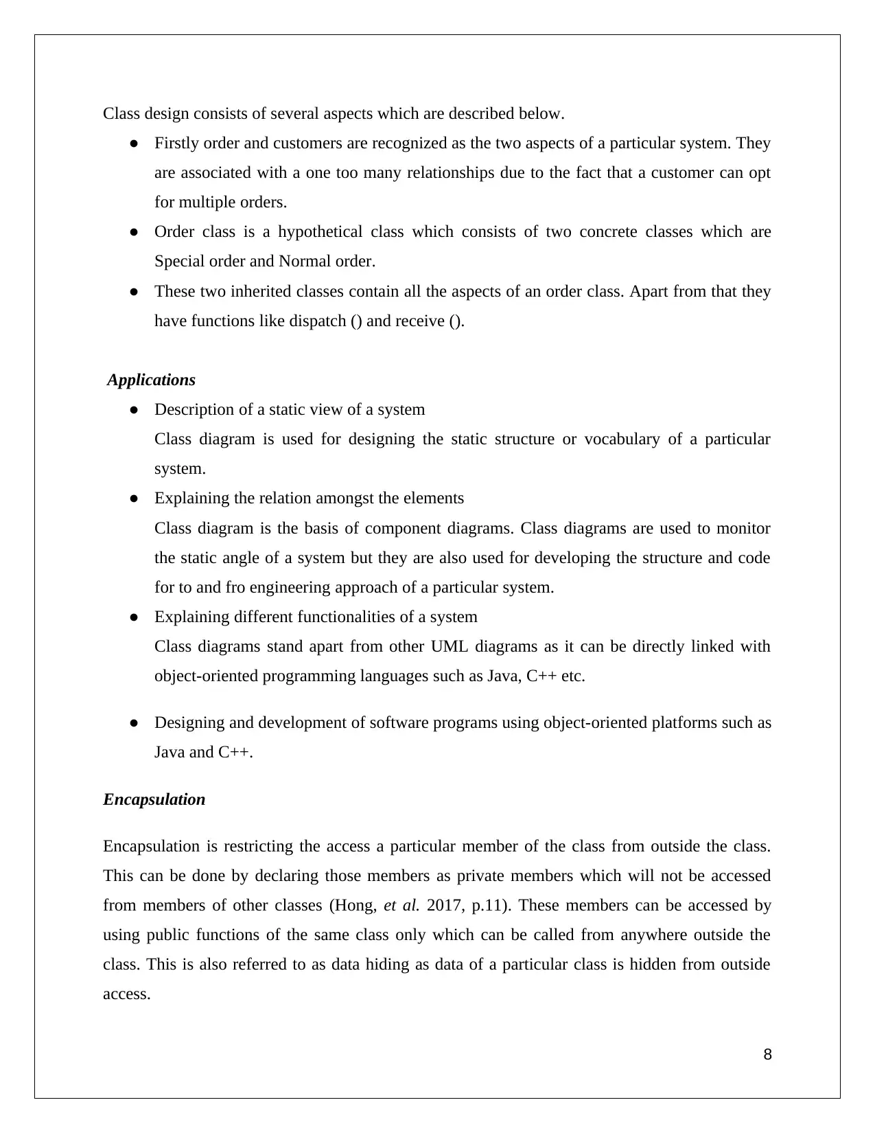
Class design consists of several aspects which are described below.
● Firstly order and customers are recognized as the two aspects of a particular system. They
are associated with a one too many relationships due to the fact that a customer can opt
for multiple orders.
● Order class is a hypothetical class which consists of two concrete classes which are
Special order and Normal order.
● These two inherited classes contain all the aspects of an order class. Apart from that they
have functions like dispatch () and receive ().
Applications
● Description of a static view of a system
Class diagram is used for designing the static structure or vocabulary of a particular
system.
● Explaining the relation amongst the elements
Class diagram is the basis of component diagrams. Class diagrams are used to monitor
the static angle of a system but they are also used for developing the structure and code
for to and fro engineering approach of a particular system.
● Explaining different functionalities of a system
Class diagrams stand apart from other UML diagrams as it can be directly linked with
object-oriented programming languages such as Java, C++ etc.
● Designing and development of software programs using object-oriented platforms such as
Java and C++.
Encapsulation
Encapsulation is restricting the access a particular member of the class from outside the class.
This can be done by declaring those members as private members which will not be accessed
from members of other classes (Hong, et al. 2017, p.11). These members can be accessed by
using public functions of the same class only which can be called from anywhere outside the
class. This is also referred to as data hiding as data of a particular class is hidden from outside
access.
8
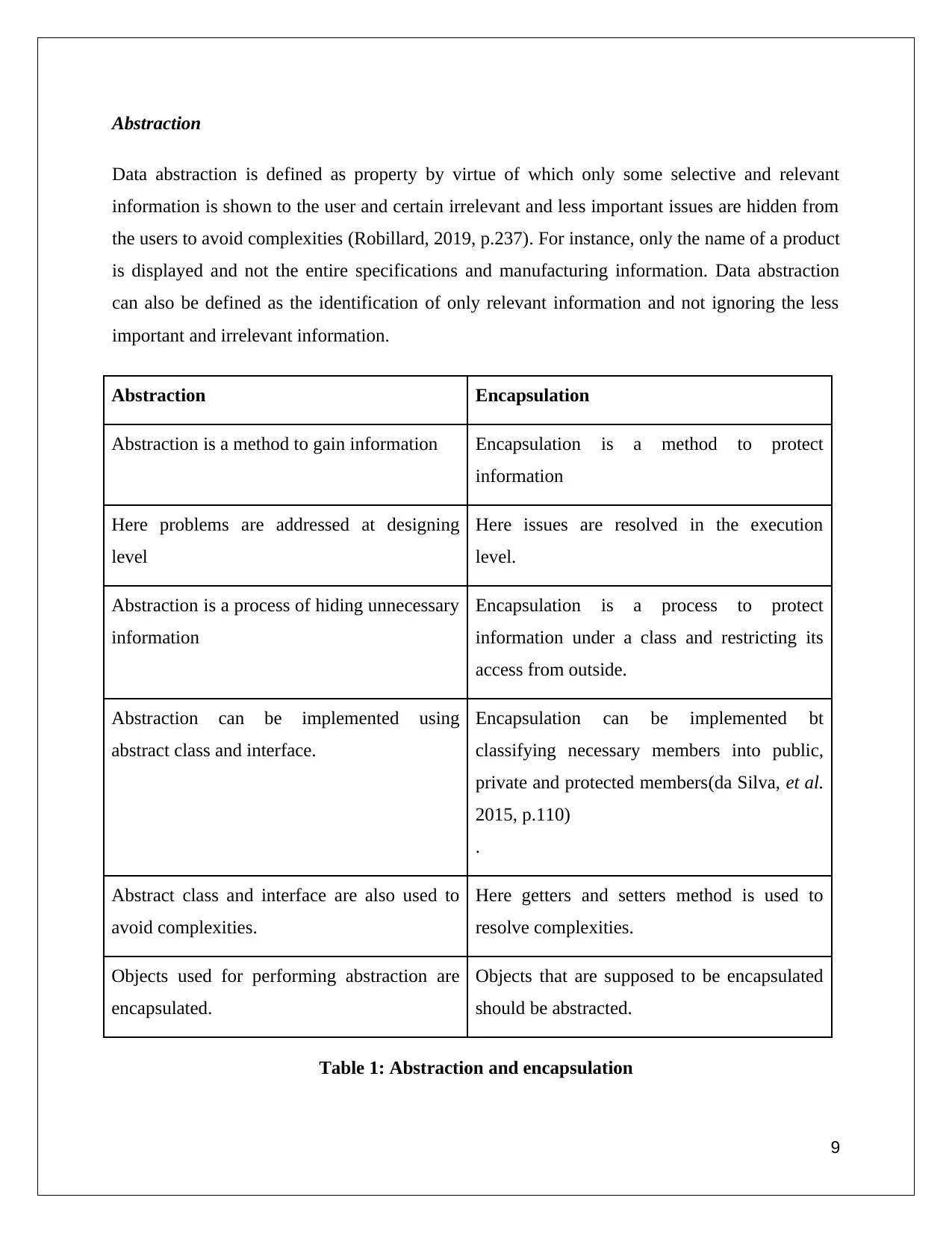
Abstraction
Data abstraction is defined as property by virtue of which only some selective and relevant
information is shown to the user and certain irrelevant and less important issues are hidden from
the users to avoid complexities (Robillard, 2019, p.237). For instance, only the name of a product
is displayed and not the entire specifications and manufacturing information. Data abstraction
can also be defined as the identification of only relevant information and not ignoring the less
important and irrelevant information.
Abstraction Encapsulation
Abstraction is a method to gain information Encapsulation is a method to protect
information
Here problems are addressed at designing
level
Here issues are resolved in the execution
level.
Abstraction is a process of hiding unnecessary
information
Encapsulation is a process to protect
information under a class and restricting its
access from outside.
Abstraction can be implemented using
abstract class and interface.
Encapsulation can be implemented bt
classifying necessary members into public,
private and protected members(da Silva, et al.
2015, p.110)
.
Abstract class and interface are also used to
avoid complexities.
Here getters and setters method is used to
resolve complexities.
Objects used for performing abstraction are
encapsulated.
Objects that are supposed to be encapsulated
should be abstracted.
Table 1: Abstraction and encapsulation
9
⊘ This is a preview!⊘
Do you want full access?
Subscribe today to unlock all pages.
Trusted by 1+ million students worldwide
(Source: Coblenz, et al. 2017, p.496)
Inheritance
Inheritance is an essential component which is used in Object-oriented programming. This is a
feature by which the members of a particular class are allowed to inherit data from other class.
Inheritance can be classified into different types which are mentioned below.
● Single inheritance-Here subclasses inherit the features of one super class (Harris, et al.
2019, p.1). The class which inherits is known as a subclass or derived class while the
class from which the information is inherited is referred to as super class or base class.
● Multilevel inheritance- Here a derived class inherits from a base class which in turn as a
base class for other derived classes, forming a multi-level chain.
● Hierarchical inheritance- Here more than one derived class inherits from a single base
class at the same time.
● Multiple inheritances- Here a single subclass inherits from more than one super class.
Hence the derived class contains the properties of all the base classes. Multiple
inheritances can be implemented in java using interfaces.
● Hybrid inheritance- When more than one of the above-mentioned types of inheritance are
implemented at the same time than it is referred to as hybrid inheritance. Implementation
of hybrid inheritance in Java is also done using interfaces.
Inheritance in Java
● Every class is directly related to only one super class referred to as single inheritance.
● Super classes can have more than one subclass but subclasses cannot have more than one
super class. This is due to the fact that Java does not allow multiple inheritances at a time
with classes. But these multiple inheritances in Java are implemented through an
interface.
● Subclasses can inherit all the members of the super class but bit cannot inherit
constructors, but these constructors can be called from these subclasses.
10
Paraphrase This Document
Need a fresh take? Get an instant paraphrase of this document with our AI Paraphraser
● Subclasses can also not inherit private members but these private members can be
assessed by the help of public and protected members of the super class.
Sequential diagram
Sequence diagrams are also referred to as an event diagram or sequence since these diagrams
describe interrelations between objects in a sequential order which is the order in which the
interlinking takes place (Marchant, et al. 2015, p.2879). These diagrams depict the process as
well as the sequence in which the interaction takes place. These diagrams find a wide range of
applications in business purposes, software development, designing of documents and
identifying requirements.
Common terms
1. Actors- Actor represents the nature of role of the object at the site of interaction with the
system. Here actor is always outside the system and which is aimed to be designed using the
UML model. Actors are used to depicting several roles including human beings and several other
external interfaces. There can be more than one actors in a sequential diagram.
11
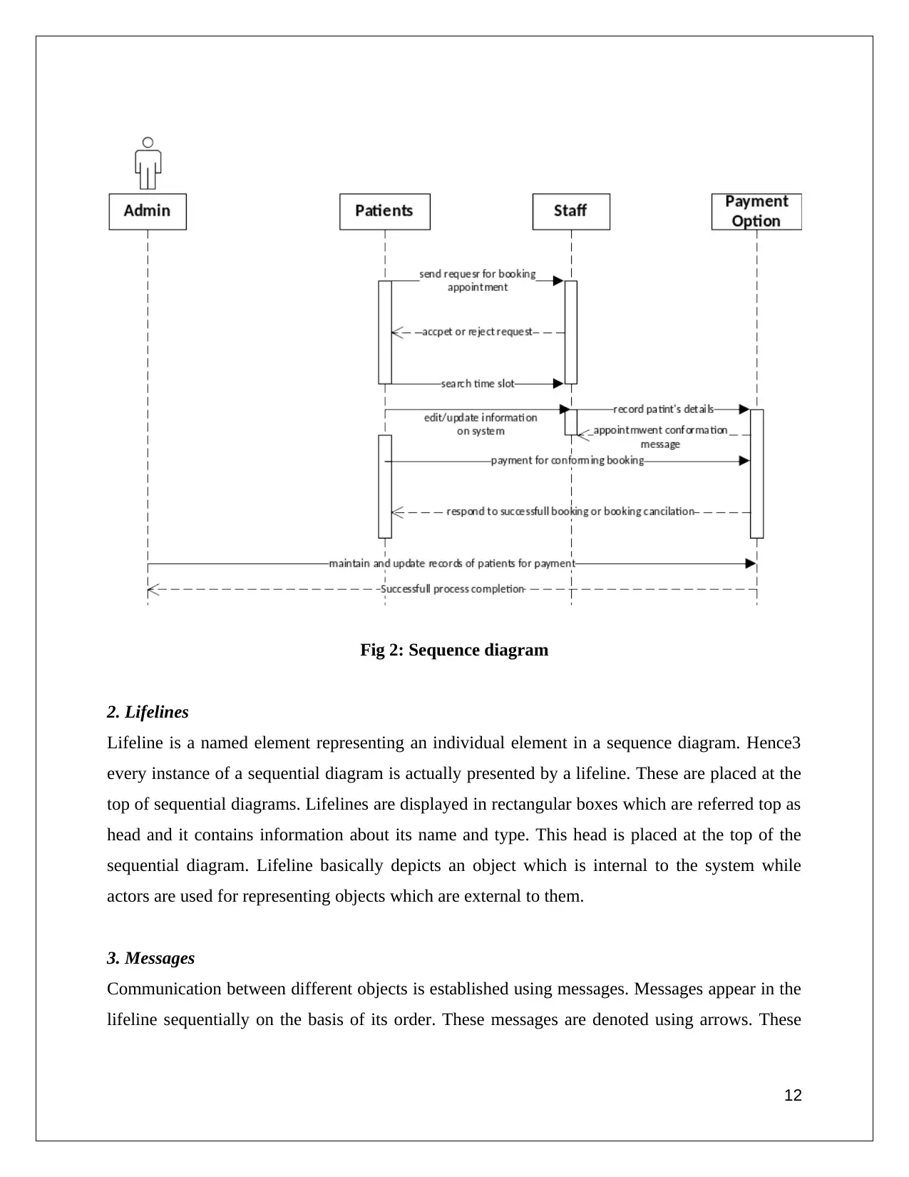
Fig 2: Sequence diagram
2. Lifelines
Lifeline is a named element representing an individual element in a sequence diagram. Hence3
every instance of a sequential diagram is actually presented by a lifeline. These are placed at the
top of sequential diagrams. Lifelines are displayed in rectangular boxes which are referred top as
head and it contains information about its name and type. This head is placed at the top of the
sequential diagram. Lifeline basically depicts an object which is internal to the system while
actors are used for representing objects which are external to them.
3. Messages
Communication between different objects is established using messages. Messages appear in the
lifeline sequentially on the basis of its order. These messages are denoted using arrows. These
12
⊘ This is a preview!⊘
Do you want full access?
Subscribe today to unlock all pages.
Trusted by 1+ million students worldwide
1 out of 25
Related Documents


Your All-in-One AI-Powered Toolkit for Academic Success.
+13062052269
info@desklib.com
Available 24*7 on WhatsApp / Email
![[object Object]](/_next/static/media/star-bottom.7253800d.svg)
Unlock your academic potential
Copyright © 2020–2026 A2Z Services. All Rights Reserved. Developed and managed by ZUCOL.