Software Requirements and Architectures: Walker Spotter Project Report
VerifiedAdded on 2022/09/07
|12
|4016
|14
Report
AI Summary
This report analyzes the software requirements and architectures for the Walker Spotter system, focusing on stakeholder identification, functional requirements, and behavioral diagrams. It explores the use of UML diagrams, comparing them with natural language for requirements specification. The report also examines validation techniques like prototyping and test cases, and discusses various quality attributes such as correctness, interoperability, reusability, and maintainability. Additionally, the report delves into architectural design tactics, including availability, correctness, and interoperability, and concludes with a discussion on the documentation of architecture. The assignment covers a detailed analysis of the Walker Spotter system, encompassing software requirements, architectural design, and validation techniques, aiming to provide a comprehensive understanding of the project's development lifecycle.
1SOFTWARE REQUIREMENTS AND ARCHITECTURES
1.1 Stakeholder Identification
Stakeholder identification is the first step in developing any project. It helps in gathering
and analyzing the requirements for the software development. The stakeholder identification of
the Walker Spotter is done with the help of the description of the system and control system.
The stakeholder contributes in the project whether in a direct or indirect way [1]. The identified
stakeholders are described below with the identifying techniques with their advantages and
limitations:
a. YASE: The YASE York Autonomous Software Engineering limited is a control software
manufacturer here which will contribute the main input in the development of the project.
This stakeholder is identified with the help of Influence-Impact grid technique where the
stakeholder is recognized as the main decision making of the project and how can they
change in the results. It helps in prioritizing the stakeholders. However; sometimes the
priority does not match with the real word case often.
b. RescueDrone Limited: RescueDrone is the company who requires the Walker Spotter
for the rescue project. They have contacted the YASE for the development. The
stakeholder is identified with the Power-versus interest grid techniques where the
stakeholders are identified who are important part of the development. It’s a 2x2 matrix
where top right corner shows the stakeholders having highest power and interest. It
classifies the stakeholders according to the power and interest. Budget and time
management is the main limitation of this technique.
c. Walkers and Climbers: This stakeholder has the less influence in the project, however;
the Climbers and Walkers data is required to be stored as backend in the system to
identify properly if they get lost. It is identified by the Salience model where the important
stakeholder is carried out from the non-important stakeholders. In case of urgency it
becomes the limitation for this method of identification.
1.2 (i) Functional Requirement
The functional requirements of a system or software represents the objectives of the
system in a set of tasks that the system is able to perform. The functional requirements of a
project can be gathered after the requirement analysis and stakeholder’s analysis in
development phase. These can be the input for the system along with the behavior and
expected output [21]. Calculation, interaction, or any business processes are the common
example of the functional requirements. The functional requirements are the input of the design
and modelling phase in the software development life cycle. The functional requirements later
help in identifying the required materials, components, objects and suitable modelling
techniques. The functional requirements for the Walker Spotter are discussed below:
i. The user of the drone can be able to access the drone control.
ii. The system interface should able to control the hardware of the drone.
iii. The user should be able to increase and decrease the speed of the drone.
iv. The user should be able to vary the position of the drone in terms of left-right, forward-
backward and up-down along with the movement.
Paraphrase This Document
Need a fresh take? Get an instant paraphrase of this document with our AI Paraphraser
2SOFTWARE REQUIREMENTS AND ARCHITECTURES
v. The user should be able to receive real time images of the spot captured by the cameras
using infrared thermal and normal day-night mode.
vi. The user can stream live video of the spot using the using infrared thermal and normal
day-night mode of the cameras.
vii. The system should be able to communicate with the Land rover within a range of 5
square miles.
viii. The system should able to use AI (Artificial intelligence) algorithms for identifying the
objects seen from the camera.
ix. The system should have a single command for returning back to the base camp in
Topsborough.
1.2 (ii) Behavioral Diagrams
Behavioral diagrams are the part of the UML (unified Modelling language)
which helps the visualization, specialization, constructing and representing the dynamic aspect
of the software system. In UML the behavioral diagrams are the use case diagram, activity
diagram, communication diagram, sequence diagram etc. [2]. In this scenario, the use case
diagram has been developed for the selected four functionalities of the Walker Spotter system.
The selected functional requirements are the returning to base (ix), range connectivity (vii),
camera operations (v), and the drone Takeoff (i).
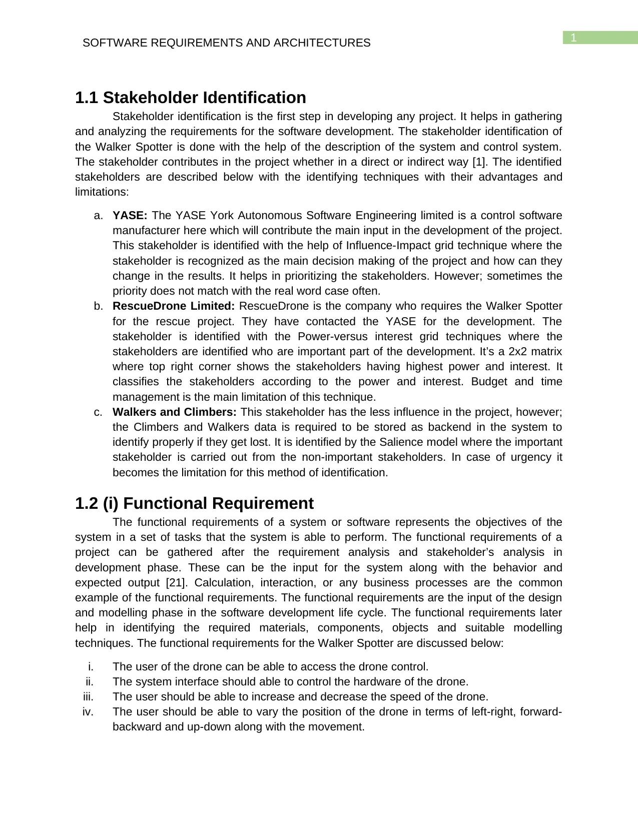
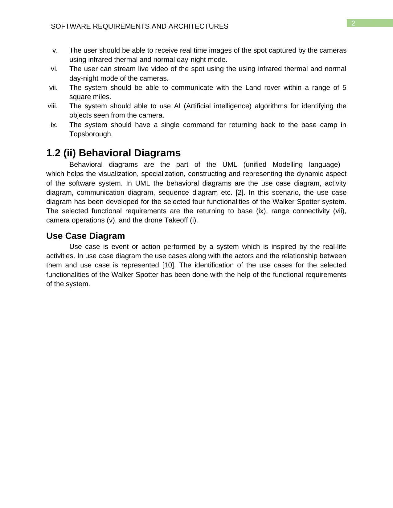
Use Case Diagram
Use case is event or action performed by a system which is inspired by the real-life
activities. In use case diagram the use cases along with the actors and the relationship between
them and use case is represented [10]. The identification of the use cases for the selected
functionalities of the Walker Spotter has been done with the help of the functional requirements
of the system.
v. The user should be able to receive real time images of the spot captured by the cameras
using infrared thermal and normal day-night mode.
vi. The user can stream live video of the spot using the using infrared thermal and normal
day-night mode of the cameras.
vii. The system should be able to communicate with the Land rover within a range of 5
square miles.
viii. The system should able to use AI (Artificial intelligence) algorithms for identifying the
objects seen from the camera.
ix. The system should have a single command for returning back to the base camp in
Topsborough.
1.2 (ii) Behavioral Diagrams
Behavioral diagrams are the part of the UML (unified Modelling language)
which helps the visualization, specialization, constructing and representing the dynamic aspect
of the software system. In UML the behavioral diagrams are the use case diagram, activity
diagram, communication diagram, sequence diagram etc. [2]. In this scenario, the use case
diagram has been developed for the selected four functionalities of the Walker Spotter system.
The selected functional requirements are the returning to base (ix), range connectivity (vii),
camera operations (v), and the drone Takeoff (i).
Use Case Diagram
Use case is event or action performed by a system which is inspired by the real-life
activities. In use case diagram the use cases along with the actors and the relationship between
them and use case is represented [10]. The identification of the use cases for the selected
functionalities of the Walker Spotter has been done with the help of the functional requirements
of the system.
3SOFTWARE REQUIREMENTS AND ARCHITECTURES
Figure 1: Use Case diagram of Access control of Walker Spotter
Source: created by author
Figure 2: Use Case diagram of Camera operation of Walker Spotter
Source: created by author
Figure 1: Use Case diagram of Access control of Walker Spotter
Source: created by author
Figure 2: Use Case diagram of Camera operation of Walker Spotter
Source: created by author
⊘ This is a preview!⊘
Do you want full access?
Subscribe today to unlock all pages.
Trusted by 1+ million students worldwide
4SOFTWARE REQUIREMENTS AND ARCHITECTURES
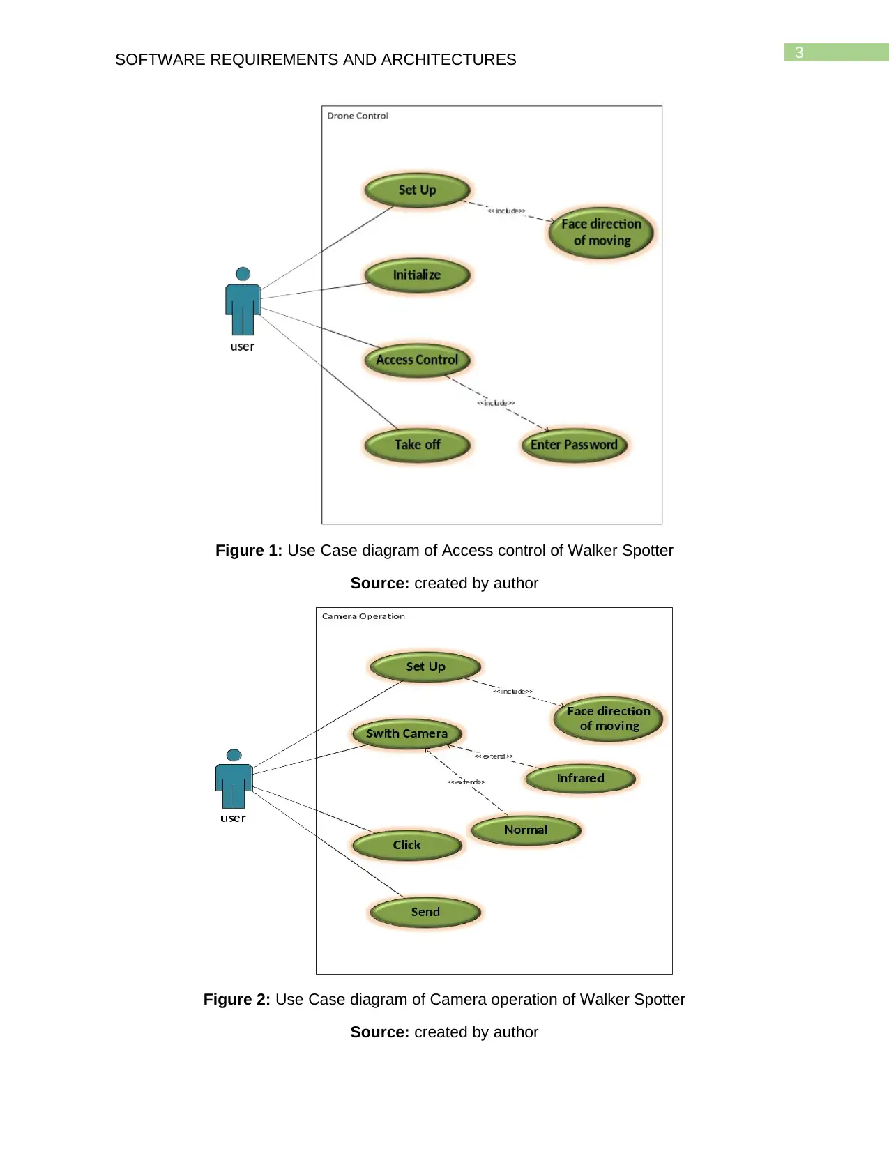
Figure 3: Use Case diagram of Return to base of Walker Spotter
Source: created by author
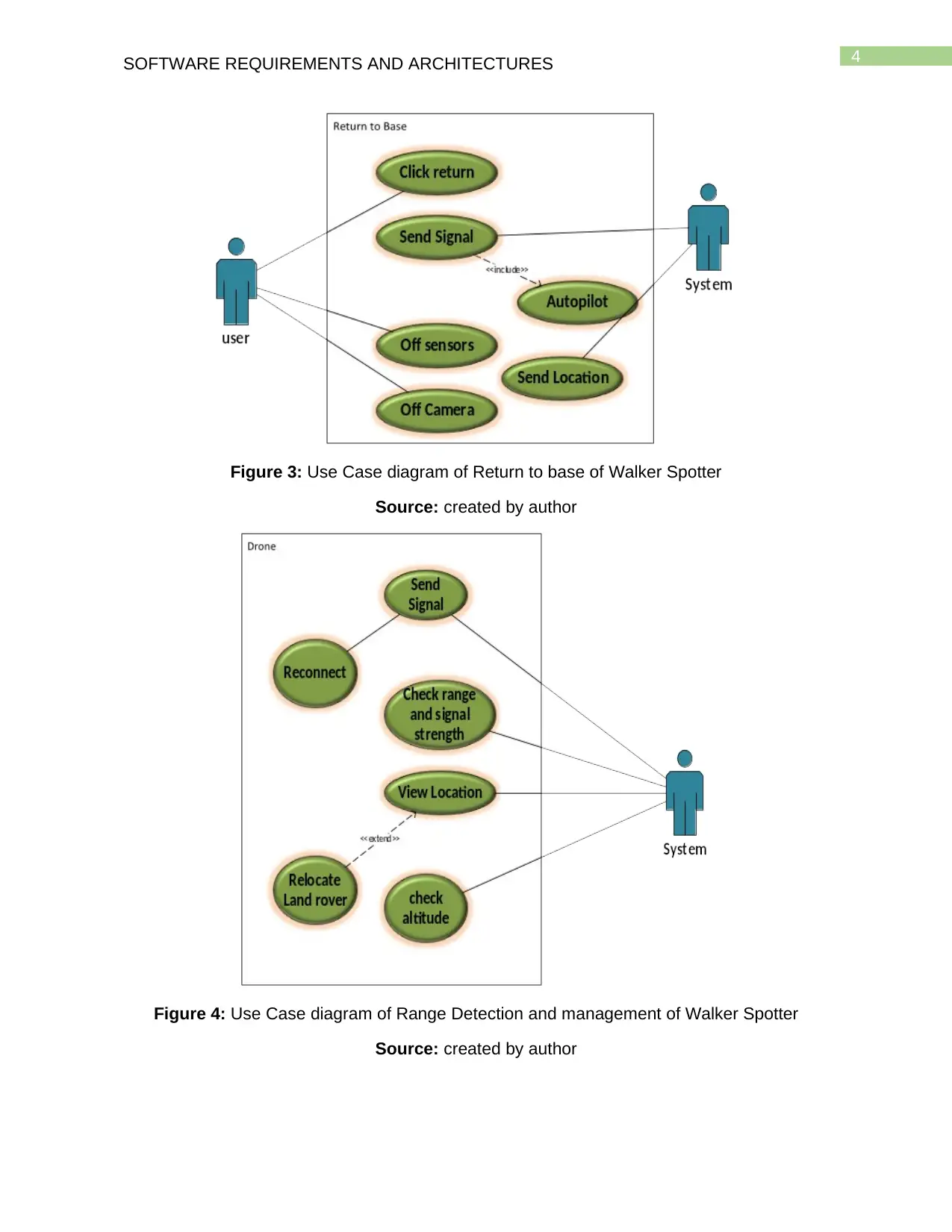
Figure 4: Use Case diagram of Range Detection and management of Walker Spotter
Source: created by author
Figure 3: Use Case diagram of Return to base of Walker Spotter
Source: created by author
Figure 4: Use Case diagram of Range Detection and management of Walker Spotter
Source: created by author
Paraphrase This Document
Need a fresh take? Get an instant paraphrase of this document with our AI Paraphraser
5SOFTWARE REQUIREMENTS AND ARCHITECTURES
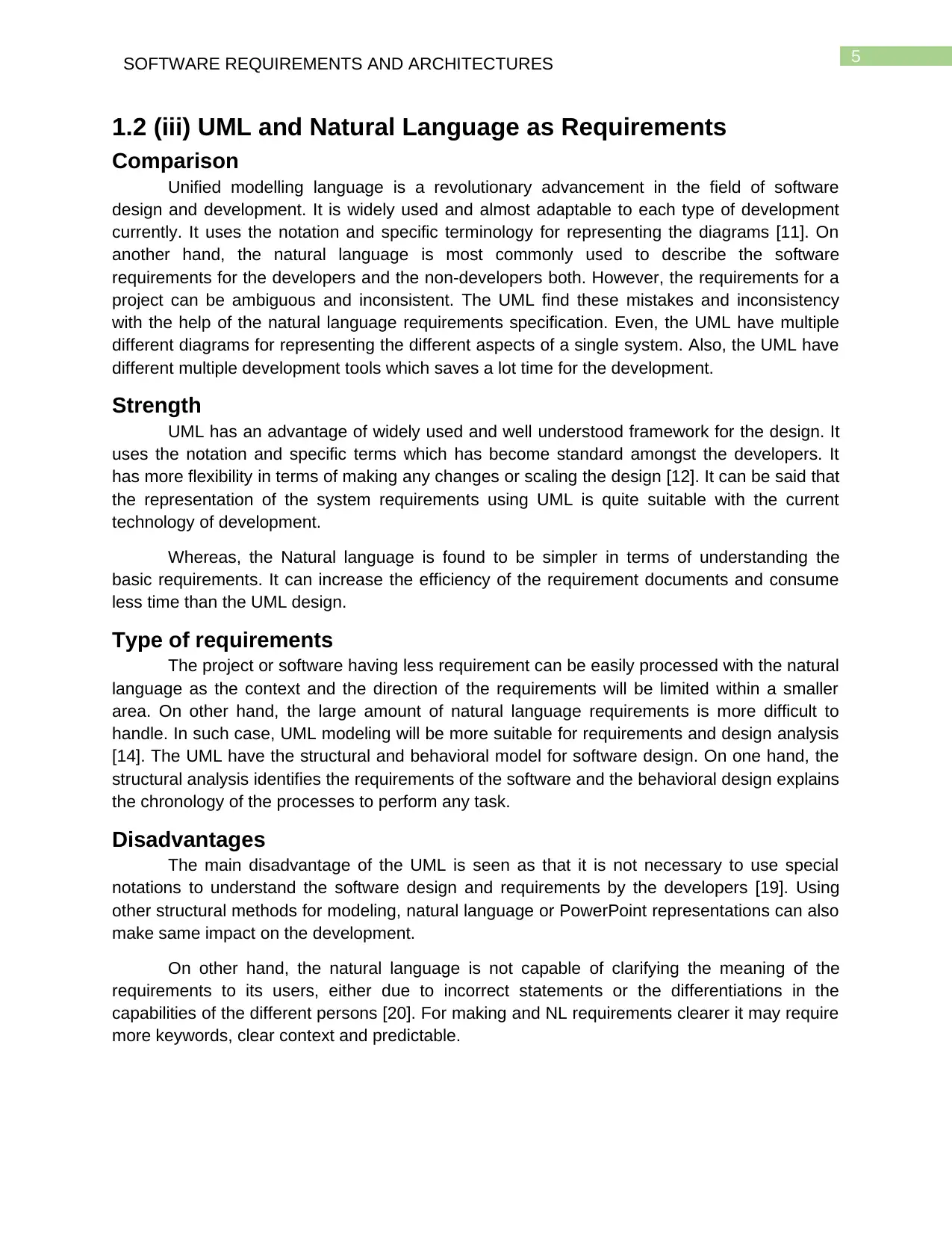
1.2 (iii) UML and Natural Language as Requirements
Comparison
Unified modelling language is a revolutionary advancement in the field of software
design and development. It is widely used and almost adaptable to each type of development
currently. It uses the notation and specific terminology for representing the diagrams [11]. On
another hand, the natural language is most commonly used to describe the software
requirements for the developers and the non-developers both. However, the requirements for a
project can be ambiguous and inconsistent. The UML find these mistakes and inconsistency
with the help of the natural language requirements specification. Even, the UML have multiple
different diagrams for representing the different aspects of a single system. Also, the UML have
different multiple development tools which saves a lot time for the development.
Strength
UML has an advantage of widely used and well understood framework for the design. It
uses the notation and specific terms which has become standard amongst the developers. It
has more flexibility in terms of making any changes or scaling the design [12]. It can be said that
the representation of the system requirements using UML is quite suitable with the current
technology of development.
Whereas, the Natural language is found to be simpler in terms of understanding the
basic requirements. It can increase the efficiency of the requirement documents and consume
less time than the UML design.
Type of requirements
The project or software having less requirement can be easily processed with the natural
language as the context and the direction of the requirements will be limited within a smaller
area. On other hand, the large amount of natural language requirements is more difficult to
handle. In such case, UML modeling will be more suitable for requirements and design analysis
[14]. The UML have the structural and behavioral model for software design. On one hand, the
structural analysis identifies the requirements of the software and the behavioral design explains
the chronology of the processes to perform any task.
Disadvantages
The main disadvantage of the UML is seen as that it is not necessary to use special
notations to understand the software design and requirements by the developers [19]. Using
other structural methods for modeling, natural language or PowerPoint representations can also
make same impact on the development.
On other hand, the natural language is not capable of clarifying the meaning of the
requirements to its users, either due to incorrect statements or the differentiations in the
capabilities of the different persons [20]. For making and NL requirements clearer it may require
more keywords, clear context and predictable.
6SOFTWARE REQUIREMENTS AND ARCHITECTURES
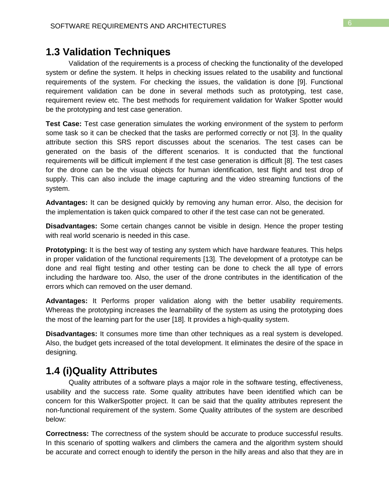
1.3 Validation Techniques
Validation of the requirements is a process of checking the functionality of the developed
system or define the system. It helps in checking issues related to the usability and functional
requirements of the system. For checking the issues, the validation is done [9]. Functional
requirement validation can be done in several methods such as prototyping, test case,
requirement review etc. The best methods for requirement validation for Walker Spotter would
be the prototyping and test case generation.
Test Case: Test case generation simulates the working environment of the system to perform
some task so it can be checked that the tasks are performed correctly or not [3]. In the quality
attribute section this SRS report discusses about the scenarios. The test cases can be
generated on the basis of the different scenarios. It is conducted that the functional
requirements will be difficult implement if the test case generation is difficult [8]. The test cases
for the drone can be the visual objects for human identification, test flight and test drop of
supply. This can also include the image capturing and the video streaming functions of the
system.
Advantages: It can be designed quickly by removing any human error. Also, the decision for
the implementation is taken quick compared to other if the test case can not be generated.
Disadvantages: Some certain changes cannot be visible in design. Hence the proper testing
with real world scenario is needed in this case.
Prototyping: It is the best way of testing any system which have hardware features. This helps
in proper validation of the functional requirements [13]. The development of a prototype can be
done and real flight testing and other testing can be done to check the all type of errors
including the hardware too. Also, the user of the drone contributes in the identification of the
errors which can removed on the user demand.
Advantages: It Performs proper validation along with the better usability requirements.
Whereas the prototyping increases the learnability of the system as using the prototyping does
the most of the learning part for the user [18]. It provides a high-quality system.
Disadvantages: It consumes more time than other techniques as a real system is developed.
Also, the budget gets increased of the total development. It eliminates the desire of the space in
designing.
1.4 (i)Quality Attributes
Quality attributes of a software plays a major role in the software testing, effectiveness,
usability and the success rate. Some quality attributes have been identified which can be
concern for this WalkerSpotter project. It can be said that the quality attributes represent the
non-functional requirement of the system. Some Quality attributes of the system are described
below:
Correctness: The correctness of the system should be accurate to produce successful results.
In this scenario of spotting walkers and climbers the camera and the algorithm system should
be accurate and correct enough to identify the person in the hilly areas and also that they are in
⊘ This is a preview!⊘
Do you want full access?
Subscribe today to unlock all pages.
Trusted by 1+ million students worldwide
7SOFTWARE REQUIREMENTS AND ARCHITECTURES
danger or need help. Although the system should be correct enough of coordinate with the
positioning system of the drone to control the drone accurately.
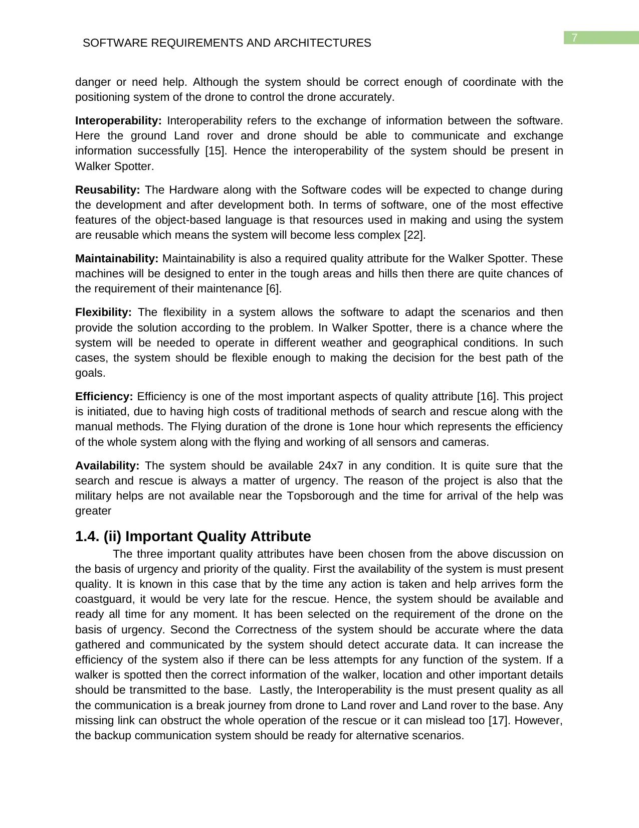
Interoperability: Interoperability refers to the exchange of information between the software.
Here the ground Land rover and drone should be able to communicate and exchange
information successfully [15]. Hence the interoperability of the system should be present in
Walker Spotter.
Reusability: The Hardware along with the Software codes will be expected to change during
the development and after development both. In terms of software, one of the most effective
features of the object-based language is that resources used in making and using the system
are reusable which means the system will become less complex [22].
Maintainability: Maintainability is also a required quality attribute for the Walker Spotter. These
machines will be designed to enter in the tough areas and hills then there are quite chances of
the requirement of their maintenance [6].
Flexibility: The flexibility in a system allows the software to adapt the scenarios and then
provide the solution according to the problem. In Walker Spotter, there is a chance where the
system will be needed to operate in different weather and geographical conditions. In such
cases, the system should be flexible enough to making the decision for the best path of the
goals.
Efficiency: Efficiency is one of the most important aspects of quality attribute [16]. This project
is initiated, due to having high costs of traditional methods of search and rescue along with the
manual methods. The Flying duration of the drone is 1one hour which represents the efficiency
of the whole system along with the flying and working of all sensors and cameras.
Availability: The system should be available 24x7 in any condition. It is quite sure that the
search and rescue is always a matter of urgency. The reason of the project is also that the
military helps are not available near the Topsborough and the time for arrival of the help was
greater
1.4. (ii) Important Quality Attribute
The three important quality attributes have been chosen from the above discussion on
the basis of urgency and priority of the quality. First the availability of the system is must present
quality. It is known in this case that by the time any action is taken and help arrives form the
coastguard, it would be very late for the rescue. Hence, the system should be available and
ready all time for any moment. It has been selected on the requirement of the drone on the
basis of urgency. Second the Correctness of the system should be accurate where the data
gathered and communicated by the system should detect accurate data. It can increase the
efficiency of the system also if there can be less attempts for any function of the system. If a
walker is spotted then the correct information of the walker, location and other important details
should be transmitted to the base. Lastly, the Interoperability is the must present quality as all
the communication is a break journey from drone to Land rover and Land rover to the base. Any
missing link can obstruct the whole operation of the rescue or it can mislead too [17]. However,
the backup communication system should be ready for alternative scenarios.
danger or need help. Although the system should be correct enough of coordinate with the
positioning system of the drone to control the drone accurately.
Interoperability: Interoperability refers to the exchange of information between the software.
Here the ground Land rover and drone should be able to communicate and exchange
information successfully [15]. Hence the interoperability of the system should be present in
Walker Spotter.
Reusability: The Hardware along with the Software codes will be expected to change during
the development and after development both. In terms of software, one of the most effective
features of the object-based language is that resources used in making and using the system
are reusable which means the system will become less complex [22].
Maintainability: Maintainability is also a required quality attribute for the Walker Spotter. These
machines will be designed to enter in the tough areas and hills then there are quite chances of
the requirement of their maintenance [6].
Flexibility: The flexibility in a system allows the software to adapt the scenarios and then
provide the solution according to the problem. In Walker Spotter, there is a chance where the
system will be needed to operate in different weather and geographical conditions. In such
cases, the system should be flexible enough to making the decision for the best path of the
goals.
Efficiency: Efficiency is one of the most important aspects of quality attribute [16]. This project
is initiated, due to having high costs of traditional methods of search and rescue along with the
manual methods. The Flying duration of the drone is 1one hour which represents the efficiency
of the whole system along with the flying and working of all sensors and cameras.
Availability: The system should be available 24x7 in any condition. It is quite sure that the
search and rescue is always a matter of urgency. The reason of the project is also that the
military helps are not available near the Topsborough and the time for arrival of the help was
greater
1.4. (ii) Important Quality Attribute
The three important quality attributes have been chosen from the above discussion on
the basis of urgency and priority of the quality. First the availability of the system is must present
quality. It is known in this case that by the time any action is taken and help arrives form the
coastguard, it would be very late for the rescue. Hence, the system should be available and
ready all time for any moment. It has been selected on the requirement of the drone on the
basis of urgency. Second the Correctness of the system should be accurate where the data
gathered and communicated by the system should detect accurate data. It can increase the
efficiency of the system also if there can be less attempts for any function of the system. If a
walker is spotted then the correct information of the walker, location and other important details
should be transmitted to the base. Lastly, the Interoperability is the must present quality as all
the communication is a break journey from drone to Land rover and Land rover to the base. Any
missing link can obstruct the whole operation of the rescue or it can mislead too [17]. However,
the backup communication system should be ready for alternative scenarios.
Paraphrase This Document
Need a fresh take? Get an instant paraphrase of this document with our AI Paraphraser
8SOFTWARE REQUIREMENTS AND ARCHITECTURES
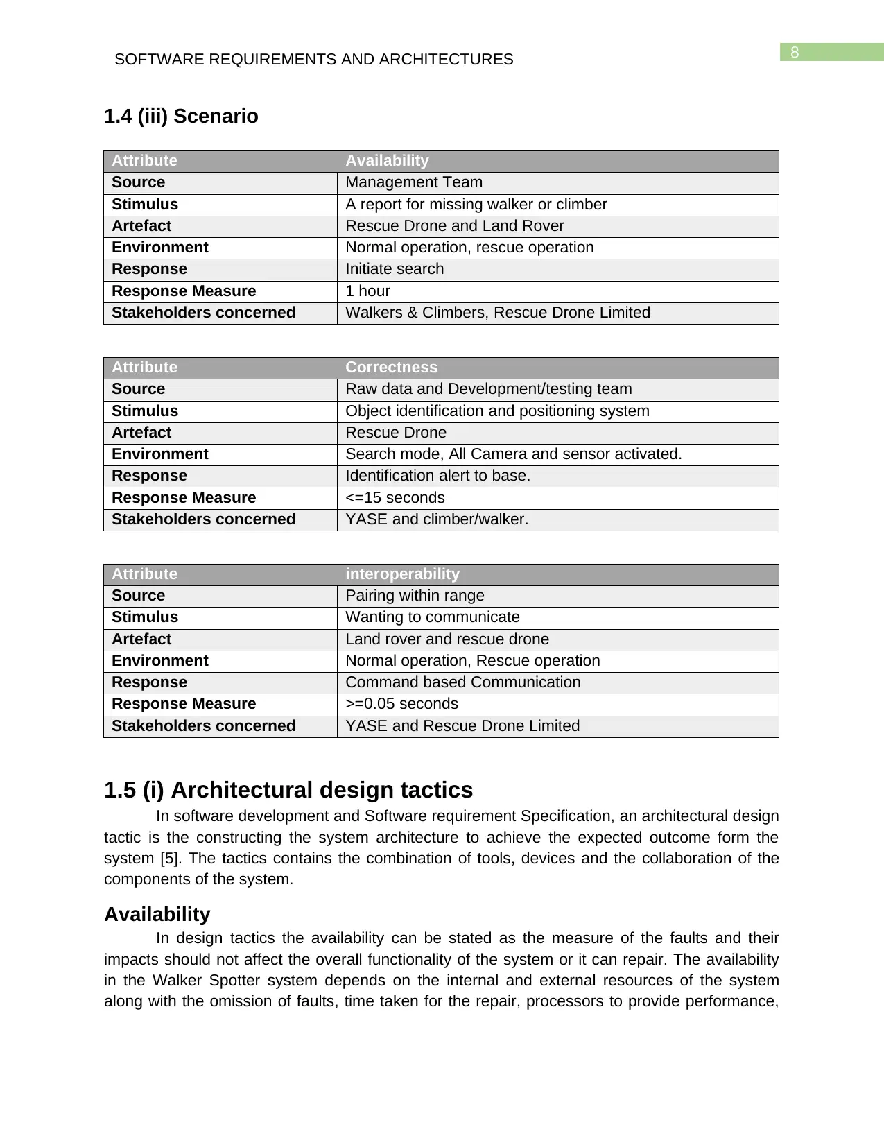
1.4 (iii) Scenario
Attribute Availability
Source Management Team
Stimulus A report for missing walker or climber
Artefact Rescue Drone and Land Rover
Environment Normal operation, rescue operation
Response Initiate search
Response Measure 1 hour
Stakeholders concerned Walkers & Climbers, Rescue Drone Limited
Attribute Correctness
Source Raw data and Development/testing team
Stimulus Object identification and positioning system
Artefact Rescue Drone
Environment Search mode, All Camera and sensor activated.
Response Identification alert to base.
Response Measure <=15 seconds
Stakeholders concerned YASE and climber/walker.
Attribute interoperability
Source Pairing within range
Stimulus Wanting to communicate
Artefact Land rover and rescue drone
Environment Normal operation, Rescue operation
Response Command based Communication
Response Measure >=0.05 seconds
Stakeholders concerned YASE and Rescue Drone Limited
1.5 (i) Architectural design tactics
In software development and Software requirement Specification, an architectural design
tactic is the constructing the system architecture to achieve the expected outcome form the
system [5]. The tactics contains the combination of tools, devices and the collaboration of the
components of the system.
Availability
In design tactics the availability can be stated as the measure of the faults and their
impacts should not affect the overall functionality of the system or it can repair. The availability
in the Walker Spotter system depends on the internal and external resources of the system
along with the omission of faults, time taken for the repair, processors to provide performance,
9SOFTWARE REQUIREMENTS AND ARCHITECTURES
storage backup, Standby time, shutdown, logging, etc. In terms of the communication, ping,
monitoring sensors, self-tests and timestamps are helpful in repair and recognition of the faults.
Correctness
Validation of all functional requirements creates the software correct and complete with a
high success rate. Correctness of the system is very necessary for the Walker Spotter system.
Identification of the humans with the help of three different cameras (Night mode, Normal mode
and infrared thermal imaging) satisfies the requirement of the correctness. Along with the
identification the drone can also drop supplies and return back to base which represents the
completeness of the requirements. The GPS device, claw clamp and other informative sensors
makes the system correct and complete.
Interoperability
In the RescueDrone Walker Spotter system the two system Land rover and the drone
are the main key factors. The system exchanges the useful information within a range. The
tactics for achieving the interoperability of the system should have the data exchange,
integration of the existing system, responsive nature, source identification, response time etc.
The Land rover also receives the commands from the base. Hence, the GPS unit, tracker,
walkie talkie etc. are the tactics to achieve better interoperation between the different
subsystems.
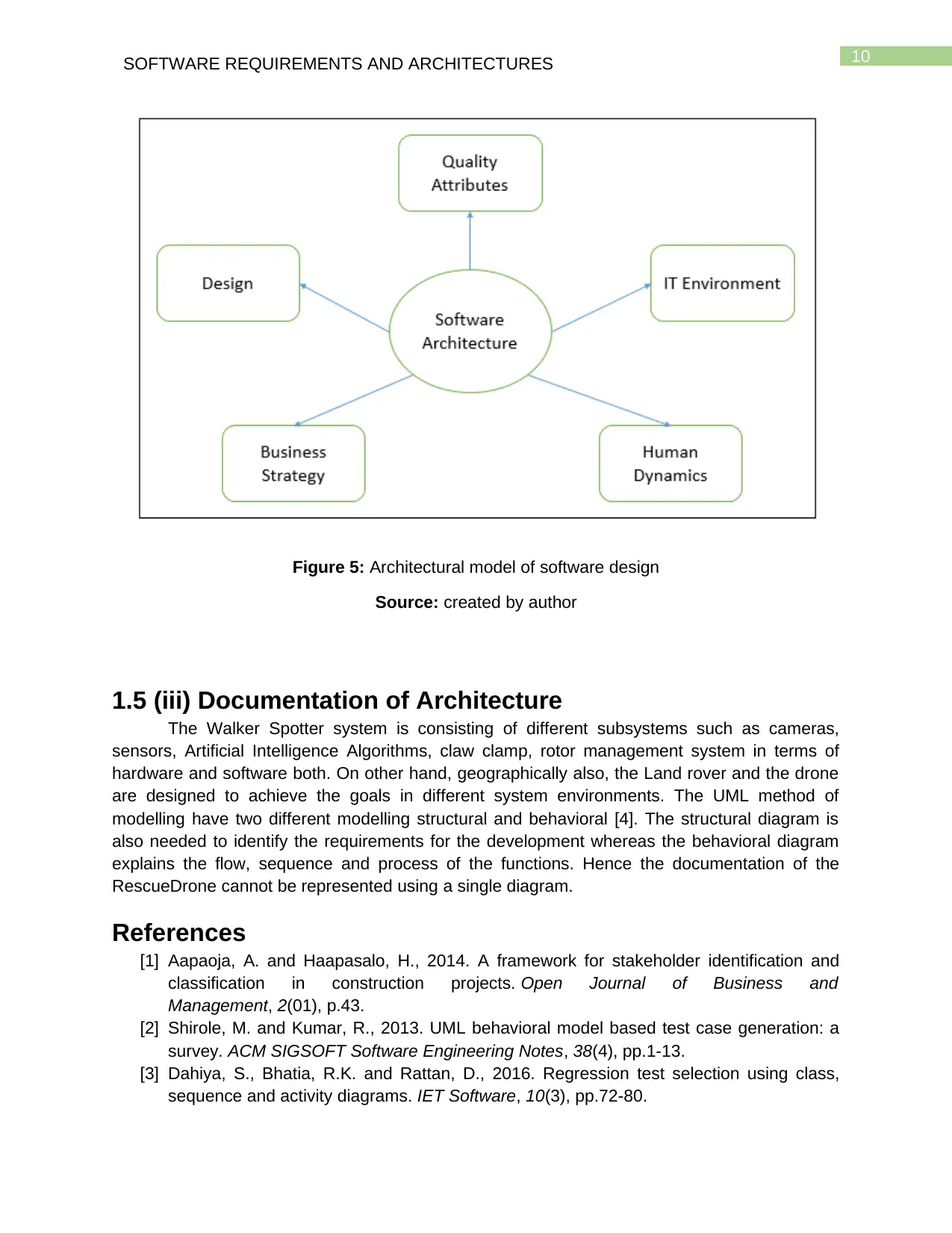
1.5 (ii) Architectural Model
The Architectural model of a system design shows the important components, quality
attributes and their chosen tactics along with the interaction within these components. The
whole model is consisting of human usability, business aspects, IT, Design and quality
attributes.
storage backup, Standby time, shutdown, logging, etc. In terms of the communication, ping,
monitoring sensors, self-tests and timestamps are helpful in repair and recognition of the faults.
Correctness
Validation of all functional requirements creates the software correct and complete with a
high success rate. Correctness of the system is very necessary for the Walker Spotter system.
Identification of the humans with the help of three different cameras (Night mode, Normal mode
and infrared thermal imaging) satisfies the requirement of the correctness. Along with the
identification the drone can also drop supplies and return back to base which represents the
completeness of the requirements. The GPS device, claw clamp and other informative sensors
makes the system correct and complete.
Interoperability
In the RescueDrone Walker Spotter system the two system Land rover and the drone
are the main key factors. The system exchanges the useful information within a range. The
tactics for achieving the interoperability of the system should have the data exchange,
integration of the existing system, responsive nature, source identification, response time etc.
The Land rover also receives the commands from the base. Hence, the GPS unit, tracker,
walkie talkie etc. are the tactics to achieve better interoperation between the different
subsystems.
1.5 (ii) Architectural Model
The Architectural model of a system design shows the important components, quality
attributes and their chosen tactics along with the interaction within these components. The
whole model is consisting of human usability, business aspects, IT, Design and quality
attributes.
⊘ This is a preview!⊘
Do you want full access?
Subscribe today to unlock all pages.
Trusted by 1+ million students worldwide
10SOFTWARE REQUIREMENTS AND ARCHITECTURES
Figure 5: Architectural model of software design
Source: created by author
1.5 (iii) Documentation of Architecture
The Walker Spotter system is consisting of different subsystems such as cameras,
sensors, Artificial Intelligence Algorithms, claw clamp, rotor management system in terms of
hardware and software both. On other hand, geographically also, the Land rover and the drone
are designed to achieve the goals in different system environments. The UML method of
modelling have two different modelling structural and behavioral [4]. The structural diagram is
also needed to identify the requirements for the development whereas the behavioral diagram
explains the flow, sequence and process of the functions. Hence the documentation of the
RescueDrone cannot be represented using a single diagram.
References
[1] Aapaoja, A. and Haapasalo, H., 2014. A framework for stakeholder identification and
classification in construction projects. Open Journal of Business and
Management, 2(01), p.43.
[2] Shirole, M. and Kumar, R., 2013. UML behavioral model based test case generation: a
survey. ACM SIGSOFT Software Engineering Notes, 38(4), pp.1-13.
[3] Dahiya, S., Bhatia, R.K. and Rattan, D., 2016. Regression test selection using class,
sequence and activity diagrams. IET Software, 10(3), pp.72-80.
Paraphrase This Document
Need a fresh take? Get an instant paraphrase of this document with our AI Paraphraser
11SOFTWARE REQUIREMENTS AND ARCHITECTURES
[4] Rost, D., Naab, M., Lima, C. and Chavez, C.V.F.G., 2013, July. Software architecture
documentation for developers: a survey. In European Conference on Software
Architecture (pp. 72-88). Springer, Berlin, Heidelberg.
[5] Mistrík, I., Soley, R.M., Ali, N., Grundy, J. and Tekinerdogan, B. eds., 2015. Software
quality assurance: in large scale and complex software-intensive systems. Morgan
Kaufmann.
[6] Al Dallal, J., 2013. Object-oriented class maintainability prediction using internal quality
attributes. Information and Software Technology, 55(11), pp.2028-2048.
[7] Koziolek, A., 2014. Automated improvement of software architecture models for
performance and other quality attributes (Vol. 7). KIT Scientific Publishing.
[8] Lewis, W.E., 2017. Software testing and continuous quality improvement. Auerbach
publications.
[9] Caracciolo, A., Lungu, M.F. and Nierstrasz, O., 2014, August. How do software
architects specify and validate quality requirements?. In European Conference on
Software Architecture (pp. 374-389). Springer, Cham.
[10] Khurana, N., Chhillar, R.S. and Chhillar, U., 2016. A Novel Technique for
Generation and Optimization of Test Cases Using Use Case, Sequence, Activity
Diagram and Genetic Algorithm. JSW, 11(3), pp.242-250.
[11] Sharma, R., Srivastava, P.K. and Biswas, K.K., 2015, August. From natural
language requirements to UML class diagrams. In 2015 IEEE Second International
Workshop on Artificial Intelligence for Requirements Engineering (AIRE) (pp. 1-8). IEEE.
[12] Rumpe, B., 2014. Executable Modeling with UML. A Vision or a
Nightmare?. arXiv preprint arXiv:1409.6597.
[13] Exner, K., Lindow, K., Buchholz, C. and Stark, R., 2014. Validation of product-
service systems–a prototyping approach. Procedia CIRP, 16, pp.68-73.
[14] Yalla, P. and Sharma, N., 2016. Utilizing NL Text for Generating UML Diagrams.
In Proceedings of the International Congress on Information and Communication
Technology (pp. 55-62). Springer, Singapore.
[15] Bröring, A., Schmid, S., Schindhelm, C.K., Khelil, A., Käbisch, S., Kramer, D., Le
Phuoc, D., Mitic, J., Anicic, D. and Teniente, E., 2017. Enabling IoT ecosystems through
platform interoperability. IEEE software, 34(1), pp.54-61.
[16] Mahdavi-Hezavehi, S., Galster, M. and Avgeriou, P., 2013. Variability in quality
attributes of service-based software systems: A systematic literature review. Information
and Software Technology, 55(2), pp.320-343.
[17] Rezaei, R., Chiew, T.K., Lee, S.P. and Aliee, Z.S., 2014. Interoperability
evaluation models: A systematic review. Computers in Industry, 65(1), pp.1-23.
[18] Coletta, A.R., 2017. The lean 3P advantage: A practitioner's guide to the
production preparation process. Productivity Press.
[19] Alhumaidan, F. and Zafar, N.A., 2014, March. Possible improvements in UML
behavior diagrams. In 2014 International Conference on Computational Science and
Computational Intelligence (Vol. 2, pp. 173-178). IEEE.
[20] Clark, A., Fox, C. and Lappin, S. eds., 2013. The handbook of computational
linguistics and natural language processing. John Wiley & Sons.
[21] Dick, J., Hull, E. and Jackson, K., 2017. Requirements engineering. Springer.
12SOFTWARE REQUIREMENTS AND ARCHITECTURES
[22] Tahir, M., Khan, F., Babar, M., Arif, F. and Khan, F., 2016. Framework for better
reusability in component based software engineering. the Journal of Applied
Environmental and Biological Sciences (JAEBS), 6(4S), pp.77-81.
[22] Tahir, M., Khan, F., Babar, M., Arif, F. and Khan, F., 2016. Framework for better
reusability in component based software engineering. the Journal of Applied
Environmental and Biological Sciences (JAEBS), 6(4S), pp.77-81.
⊘ This is a preview!⊘
Do you want full access?
Subscribe today to unlock all pages.
Trusted by 1+ million students worldwide
1 out of 12
Related Documents


Your All-in-One AI-Powered Toolkit for Academic Success.
+13062052269
info@desklib.com
Available 24*7 on WhatsApp / Email
![[object Object]](/_next/static/media/star-bottom.7253800d.svg)
Unlock your academic potential
Copyright © 2020–2026 A2Z Services. All Rights Reserved. Developed and managed by ZUCOL.