Sohar Aluminium Power Plant Project: Design and Implementation
VerifiedAdded on 2020/10/05
|38
|7481
|115
Project
AI Summary
This project analyzes the Sohar Aluminium Power Plant in Oman, focusing on its efficiency challenges. The plant, which uses gas and steam turbines, faces issues related to the water bath heater's performance and overall operational costs. The project explores the current system, including the gas turbines, HRSG, and the role of the Oman gas Company in supplying fuel. The primary problem is the inefficient functioning of the water bath heater due to gas flow issues, leading to filter malfunction. The project aims to increase the efficiency of natural gas usage, minimize maintenance costs, and reduce steam costs. It outlines the project's scope, including site selection, manpower considerations, waste disposal, and power supply availability. The methodology includes literature review, process conditions, and detailed procedures for taking the scrubber and water bath heater in service. The project includes layout diagrams, environmental impact assessments, and mass and energy balance calculations. The results and discussion sections cover maintenance requirements, HSE requirements, cost estimations, and industrial management aspects, concluding with recommendations for improving the plant's efficiency and addressing the identified problems. The document includes tables and figures to illustrate various aspects of the plant's operation and proposed improvements.

Project
Paraphrase This Document
Need a fresh take? Get an instant paraphrase of this document with our AI Paraphraser
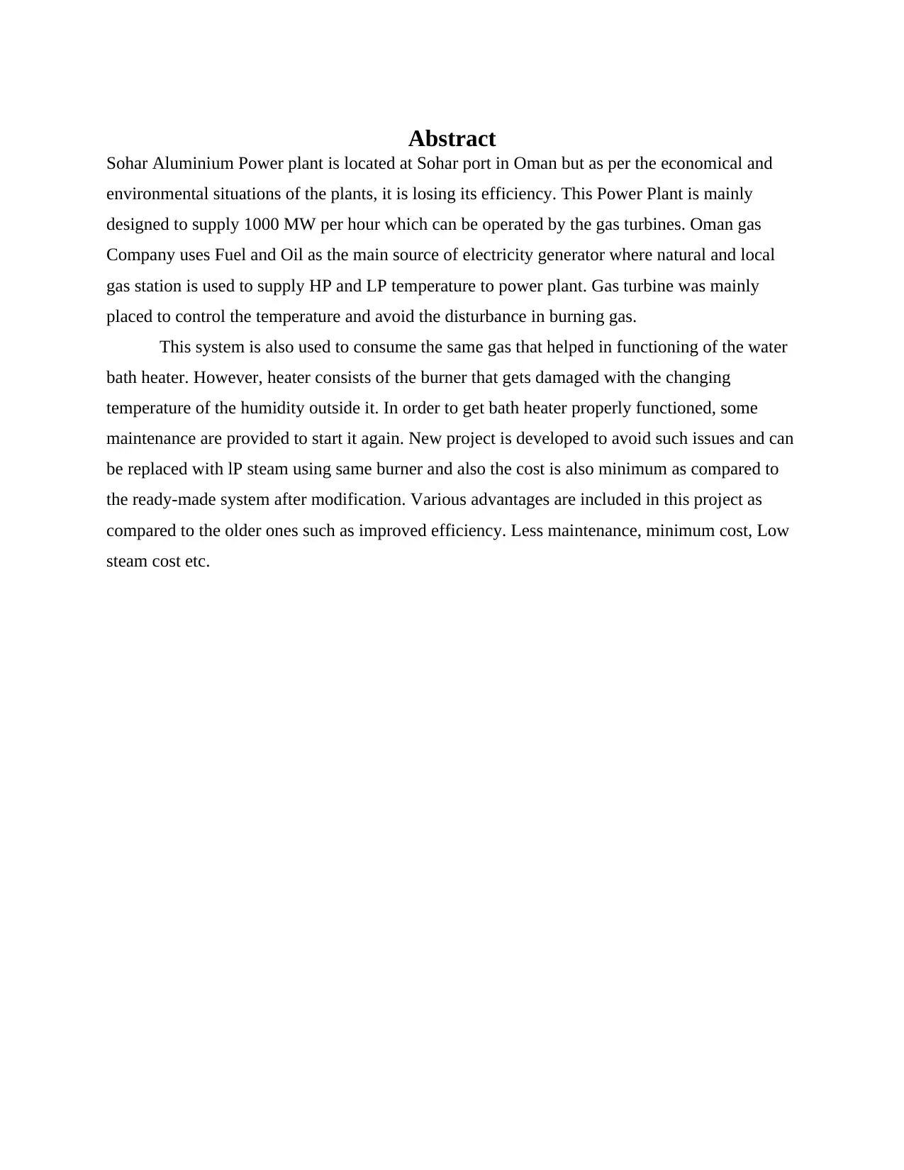
Abstract
Sohar Aluminium Power plant is located at Sohar port in Oman but as per the economical and
environmental situations of the plants, it is losing its efficiency. This Power Plant is mainly
designed to supply 1000 MW per hour which can be operated by the gas turbines. Oman gas
Company uses Fuel and Oil as the main source of electricity generator where natural and local
gas station is used to supply HP and LP temperature to power plant. Gas turbine was mainly
placed to control the temperature and avoid the disturbance in burning gas.
This system is also used to consume the same gas that helped in functioning of the water
bath heater. However, heater consists of the burner that gets damaged with the changing
temperature of the humidity outside it. In order to get bath heater properly functioned, some
maintenance are provided to start it again. New project is developed to avoid such issues and can
be replaced with lP steam using same burner and also the cost is also minimum as compared to
the ready-made system after modification. Various advantages are included in this project as
compared to the older ones such as improved efficiency. Less maintenance, minimum cost, Low
steam cost etc.

ACKNOWLEDGEMENT
We would like to express our gratitude towards all the team who is involved in making
the project a successfully. Accomplishment of this project could be little difficult without the
cooperation and contribution of this hard working team. Also, we would also like to thanks our
superior subordinate who has helped throughout the complete process and make it achieving it as
a successful accomplishment of the project. We are also great full to all the members and
employees who helped in providing the valuable thoughts and ideas in improving the operational
efficiency and finally all the people who have helped in finalising the plant.
⊘ This is a preview!⊘
Do you want full access?
Subscribe today to unlock all pages.

Trusted by 1+ million students worldwide
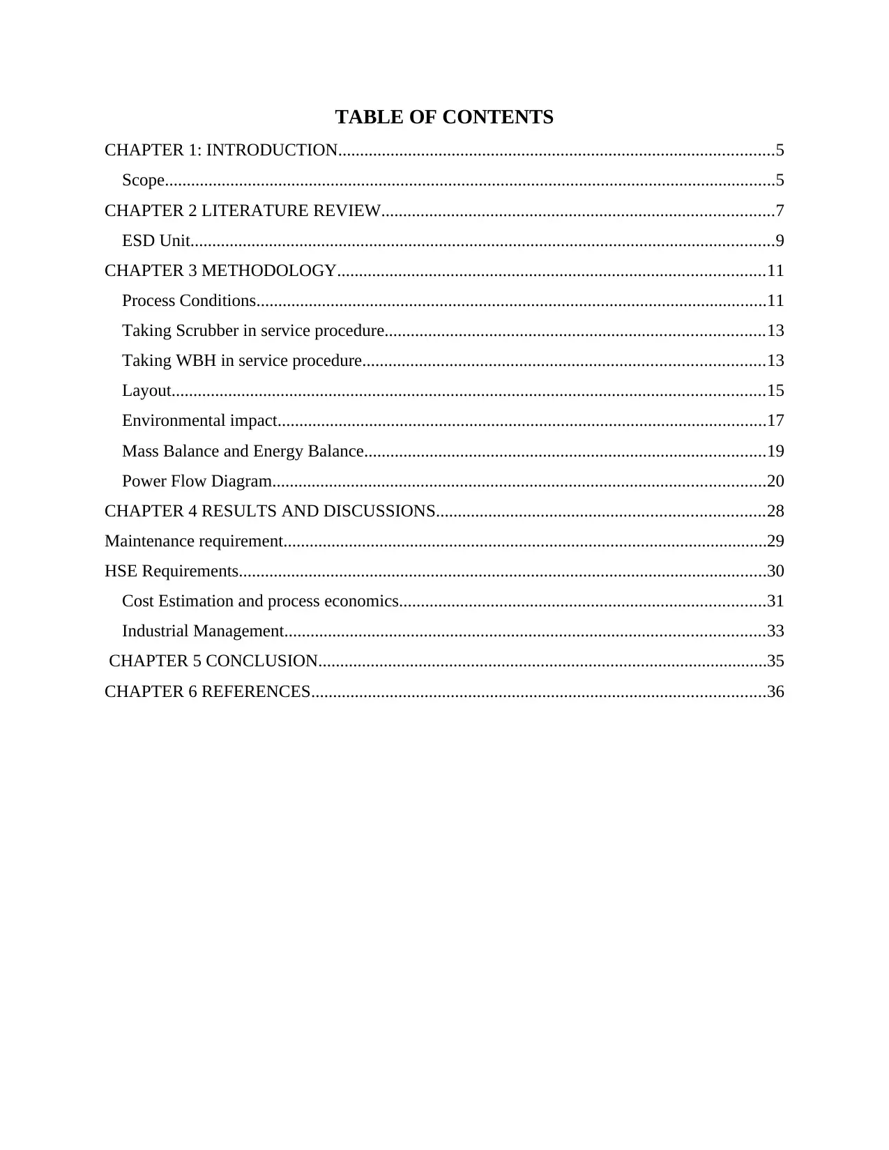
TABLE OF CONTENTS
CHAPTER 1: INTRODUCTION....................................................................................................5
Scope............................................................................................................................................5
CHAPTER 2 LITERATURE REVIEW..........................................................................................7
ESD Unit......................................................................................................................................9
CHAPTER 3 METHODOLOGY..................................................................................................11
Process Conditions.....................................................................................................................11
Taking Scrubber in service procedure.......................................................................................13
Taking WBH in service procedure............................................................................................13
Layout........................................................................................................................................15
Environmental impact................................................................................................................17
Mass Balance and Energy Balance............................................................................................19
Power Flow Diagram.................................................................................................................20
CHAPTER 4 RESULTS AND DISCUSSIONS...........................................................................28
Maintenance requirement...............................................................................................................29
HSE Requirements.........................................................................................................................30
Cost Estimation and process economics....................................................................................31
Industrial Management..............................................................................................................33
CHAPTER 5 CONCLUSION.......................................................................................................35
CHAPTER 6 REFERENCES........................................................................................................36
Paraphrase This Document
Need a fresh take? Get an instant paraphrase of this document with our AI Paraphraser
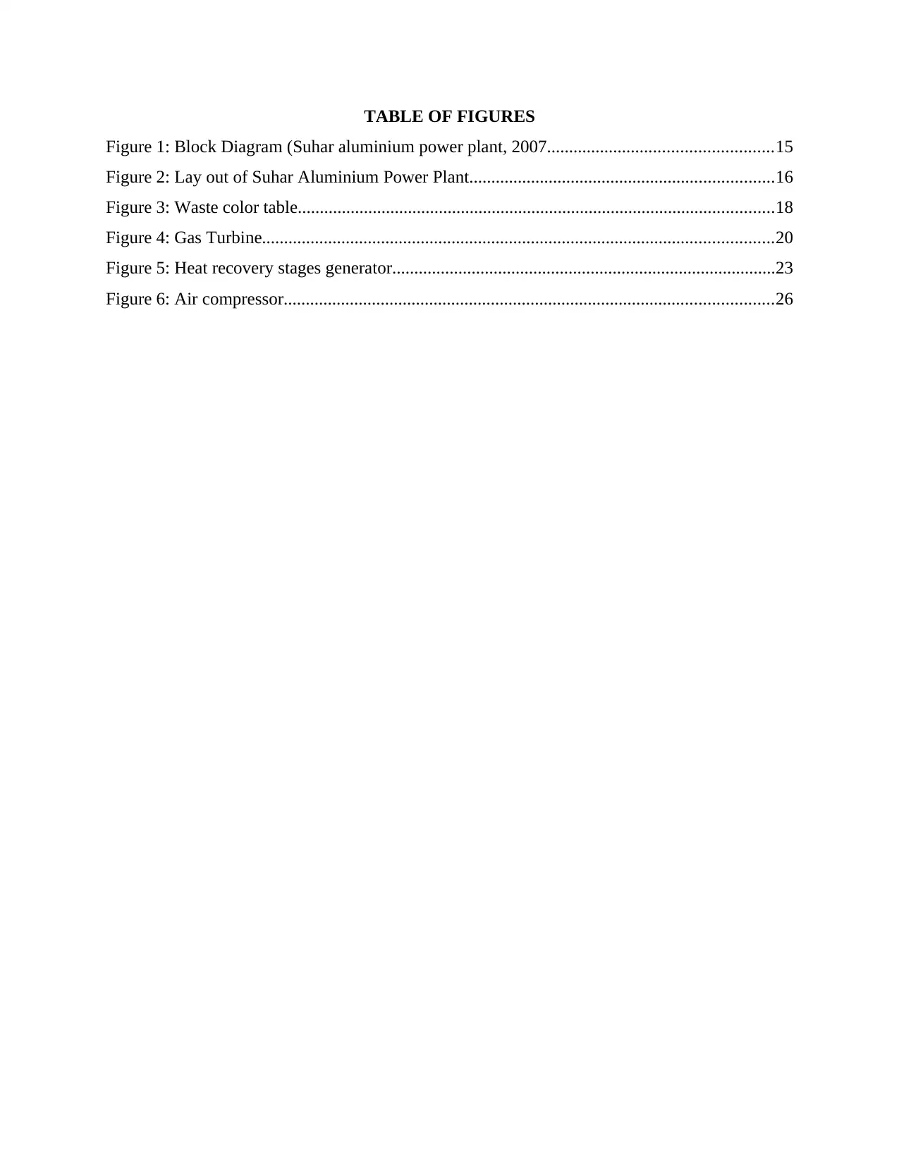
TABLE OF FIGURES
Figure 1: Block Diagram (Suhar aluminium power plant, 2007...................................................15
Figure 2: Lay out of Suhar Aluminium Power Plant.....................................................................16
Figure 3: Waste color table............................................................................................................18
Figure 4: Gas Turbine....................................................................................................................20
Figure 5: Heat recovery stages generator.......................................................................................23
Figure 6: Air compressor...............................................................................................................26
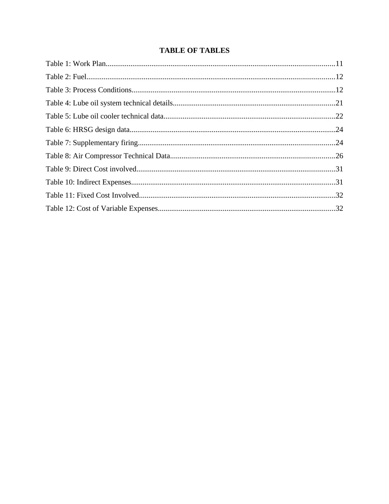
TABLE OF TABLES
Table 1: Work Plan........................................................................................................................11
Table 2: Fuel..................................................................................................................................12
Table 3: Process Conditions...........................................................................................................12
Table 4: Lube oil system technical details.....................................................................................21
Table 5: Lube oil cooler technical data..........................................................................................22
Table 6: HRSG design data............................................................................................................24
Table 7: Supplementary firing.......................................................................................................24
Table 8: Air Compressor Technical Data......................................................................................26
Table 9: Direct Cost involved........................................................................................................31
Table 10: Indirect Expenses...........................................................................................................31
Table 11: Fixed Cost Involved.......................................................................................................32
Table 12: Cost of Variable Expenses.............................................................................................32
⊘ This is a preview!⊘
Do you want full access?
Subscribe today to unlock all pages.

Trusted by 1+ million students worldwide
CHAPTER 1: INTRODUCTION
King of the Oman has been given a power of the combined cycle power plant which uses
both gas and steam turbine and has a installing capacity of 24 million units per day. Turbine
ensures the flow of gas and steam generators are used for recovery of heat. This power plant was
specially designed in order to supply the aluminium smelter which was one of the quality based
smelter in Oman (Abdalla And et.al, 2016). Proper operations of the boiler is controlled by
burner management system. Evaporative coolers system was there to control the temperature and
increase the output. Desalination plant supplies osmosis which further supply de-mineralized
plant.
Functioning of this plant can be possible by either natural gas or fuel oil which is handled
by automatic controller in case of any emergency. Water supply was agreed upon 10 degree
Celsius with ministry of environment. Various components are involved in fuel gas supply
system such as metering station, liquid separator, recovery condensate tank etc. The Dew point is
used to control the temperature of inlet and outlet gas. Local control panel and water bath
temperature are also used to downstream the gas temperature. As water bath heater fails in high
humidity so heater system is being added from HRSG system in order to heat the gas. So
changes are being made in this Sohar Aluminium power plant because trips and manpower is
very costly in Oman.
Problem
The problem with the bathing heater is that it does not function efficiently due to
excessive flow of the gas inside the chamber and this effects the filter. Because of the low
temperature of the gas, it causes malfunction to filter
Objectives
Increased efficiency of natural gas.
Minimum maintenance cost.
low cost of steam.
Scope
Various areas are included to increase the temperature of the gas. Project area for power plant: This can be referred as the area required for the project that
is 20 by 20 m. so it needs to be located at the area which is far away from residential
Paraphrase This Document
Need a fresh take? Get an instant paraphrase of this document with our AI Paraphraser
places. For selecting the area for power plant, it needs to be build at such places from
which roads and highways can be easily accessible. In order to avoid disturbance of
machinery good spaces are allotted to such projects. Manpower availability: In order to get the effective and efficient results of the project,
skilled manpower is needed to be encouraged. Disposal of waste water: As projects power plant project includes large amount of waste
so it need to be efficiently disposed in a pit. In order to reduce the cost of transfer facility,
close disposable pit need to be considered. Availability of power supply: This is one of the important criteria which need to be
selected wisely in order to minimise the cost of power consumption. HRSG and place near gas turbines: This selection criteria helps in reducing the piping
and structure of the project that ultimately helps in lower cost of the project. Complex
Design of the project may be responsible for low quality production. Fire extinguished area: As the main operations of the power plant deals with two
flammable substances such as oil gas and fuel. So the area need to be protected with fire
extinguisher in case of any uncertainty. Ground surface level: Uneven surface may be responsible for weak points in ground so
this need to be considered while selecting the criteria for project that surface shoul be flat. Avoiding future expansion: if future expansion of the project will be considered so the
the project will be developed keeping a future perspectives in mind. Therefore future
expansions are initially avoided in order to avoid the disturbance of pipe crossing and
complex structure. Various things need to be restricted such as power supply, safety
rules, supplier capacity, area, non sparky equipments and restricted cell phones within the
specific area.
Clear positioning of Entry and exit: This is the one of the important perspective which
need to be considered as this project basically deals with flammable substances that are
dangerous in nature. In case of any emergency safety measures need to be prioritize.
CHAPTER 2 LITERATURE REVIEW
The power plant is commonly used to generate the electricity and distribution of the
power supply in a locality. The Sohar aluminium smelter gets the supply of power supply in
order to produce aluminium. Aluminium smelter are generally consuming the power of 650 MW
(Abdalla And et.al., 2015). It also supplies various auxiliaries that consumes more electricity.
This contains two smelters line-01 and line-02 namely OETC.01 and OETC.02 which are 220
KV in power that is further connected with Gas insulation station. The Four turbine of the power
plant having a capacity of 170MW in gas turbine and 218 MW in steam turbine will be operated
by natural gas or fuel. Among which two are connected with low pressure boilers and two are
connected with low pressure steam.
A gas turbine model is very efficient having a capacity of 13E2 GE, consists of 21 stages
and 72 EV burner. Compressor generally contains five stages which helps in compressing the air
at the scale of 1 to 16 bar Evaporator cooler in combustor increases the efficiency up-to 18MW
at the time of summer. The gas turbine includes the cycle of operation in order to generate the
electricity. This operation cycle includes intake air which is compressed from 1st to 16th bar that
results in production of heat and rotation of shaft at a speed of 3000rpm and cuts the magnetic
field to generate electricity.
The HRGS (Heat recovery Steam Generation) generally consists of four different stages ,
includes Super Heater, Evaporator, Economizer etc. It generates low pressure and high pressure
steam. The HRGS exhaust the heat supplied from the gas turbines and each boiler is provided
with gas firing system that is located at the side of super heater that produces high pressure.
However low pressure super heated steam is provided with low pressure steam. it is used
to control high pressure of the water and low pressure of pump which is directed towards low
pressure economizer and collected in a low pressure drum. Control value collects the pressure
drum before it reaches to other stage of boiler.
Feed water pump controls high and low pressure of the water pump which passes directly to high
pressure economizer. Then it enters into high pressure drum which is generally controlled by
control value. HRSG includes de-super heated for controlling the temperature of the steam. Then
high pressure spray water will be supplied by high pressure spray water that passes to
economiser stage. Temperature and pressure of every stage will be different accordingly.
Water bath heater
⊘ This is a preview!⊘
Do you want full access?
Subscribe today to unlock all pages.

Trusted by 1+ million students worldwide
Water bath Heater are provisioned to heat the gas to control the minimum inlet
temperature which will be 13 degree Celsius. It also controls the maximum gas flow as 26.1kg/s
and pressure as 35 brag. The heaters are generally provided in order to configured to control the
streams for GT blocks 1 and 2. The temperature signal helps in resetting the point of bath
temperature which is generally used in controlling bath temperature. This bath temperature is
aimed at restricting the maximum value in DCS whose value needs to be 85 degree Celsius. In
order to prevent the overpressure of the tube, tube side relief is provided that helps in controlling
the high pressure of the heated coil (Al Rahbi and et.al., 2017). In case of gas expansion, if the
bath heater being blocked and the temperature rises above then this tube value helps in
controlling the temperature of the power plant. Over heating of the bath heater is protected in
case of water loss in order to prevent fire tube from excessive heating. Local burner
management helps in applying secuence logic to panel and also helps the shut down of the
burner (The engineering toolbox, Basic Information for Engineering and Design of Technical
Applications ,2010). This logic is mainly aimed at preventing fire tube from explosion. Also low
fuel gas supply pressure will be controlled by pressure switch. Low water level in bath heater
will be controlled by level switch. Main burner and pilot burner will helps in the extinguishing
the whole heater bath in case if any of the above units will not be able to control the temperature
of heater. This restricts the flow of fuel gas supply and thus avoids the fire explosion.
In addition to it, a local panel is also available that provides the indication of the heater
weather it is on or off. This will be controlled remotely as DCS and BMS panel allows the flow
of operations. It also helps in regulating the flow of fuel which needs to be stated at 1.4 brag. In
order to monitor the functioning of the heater and to control the upstream and down stream
pressure, local pressure gauges are generally used. Also heater contains one of the flammable
substance for the functioning of the system so A local flow meter is available that basically
monitors the consumption of fuel gas. There is also a ionised flame detector is present which
detects the spark and flames, if generated outside the heater. A suitable corrosion will have to be
mixed in order to serve the required water. Gas detector should be placed near the burner so that
propagated flame will be automatically detected with the help of mesh type flare arrestor. Gas
detector will also helps in detecting the gas leakage of the heater to avoid any uncertain
explosion within the bath heater.
Paraphrase This Document
Need a fresh take? Get an instant paraphrase of this document with our AI Paraphraser
However, the plant is meant for producing the electricity giving rise to gas cloud that is
generally ignited by the bath heater. In order to protect the bath heater from unwanted practices
of explosion the shell or covering of the heater will be insulated with the help of heat
conservation material such as mineral wool etc. Also the intake will be protected from inside to
reduce the noise as conversion of the heat and light energy produces sound. This mainly consists
of main regulating steam which is 4*100% insulated from the outer disturbance.
PRS Skid
every module contains the self-acting regulator that basically uses the fuel gas to process
for application of the desired force or tapping pressure. A creep value is used to control the
stream capacity which is mainly rated at 10% and stated at 27.5 brag. Pressure reducing value of
the downstream is provided in order to set no-flow condition for avoiding the excessive flow of
pressure. A mechanical slam shut off value is generally located at the upper side of the active
regulator and also controls the the limit of the pressure if it goes above or below pre stated value.
Over pressure of the downstream pressure will be prevented by this controller (Al-Wahaibi and
Zeka, 2015). The slam shut is a basically is loaded with spring in order to detect the value of the
temperature that helps in shuting off and on. Upstream and down stream of the of the regulator is
supported by the local remote pressure indication which functions automatically according to the
changes occurred in GT fuel demand. It also maintains the pressure supplied in GT fuel supply
header.
ESD Unit
It can be determined as the Gas station inlet ESD value that helps in energising the flow
of fuel that produces energy to the system. This is a solenoid value that is generally helps in
energising the DCS system which fails to produce energy. It mainly contains open and closed
switches that restricts the flow of energy from one module to another. The main closure value of
the ESD is generated from DCS with the help of the push button station. It can also be manually
reset on the ESD panel.
Inlet filter scrubber unit: This is a filter separator that provisioned the emergency devices in
order to shut off the device. This mainly helps in removing the water droplets or solid particles
which are formed at the structure of the pipeline. It also helps in removing the corrosion products
which are produced at pipeline. This scrubber mainly consists of two stages that is Vane pack
and Coalesce element. The first one is used to eliminate the liquid formed and the second stage is
aimed at Coalesce the liquid from both the side of the gauges. This produced liquid will be
automatically drained out with the help of the drain traps.
Condensate Drain system: It is mainly used to condensate the liquid produced at both the sides
of the level gauges. It acts as a condensation module that helps in collecting the liquid from the
filter separator. This tank basically contains a local vent that allows to flash the vapours collected
during the procedure. It provides the condensate pumps which are manually started with the high
level of pressure and functions automatically till it reaches to low level.
Condensate Drain vessel: This can be referred as a installation or operation which do not
contains any internals and therefore it never requires any maintenance inside it. Here the vent is
normally connected to the values that consists of nitrogen and isolate values. In order to prevent
spontaneous ignition or any pyrophoric iron, the vessel need to be completely washed with the
help of the water. Also various company standards need to be followed while condensation the
vessel completely for its smooth functioning.
Condensate pump: This pump need to be maintained for the smooth functioning of the system.
Vender maintenance guidelines are very important as allows the flow of the water which
contains lot of bearings. Functioning of the system need to be well maintained in order to aviod
the failure after the invalidation of the warranty of the system.
Safety device: This is related with the safety of the device as such devices are dangerous to be
hand as it generates the electricity. Pressure safety will be considered periodically in order to
remove failures (Al‐Saidi and Elagib, 2018). It need to be continue sly tested to ensure the safety
of the device. One of the most important thing during the testing of the device is testing the
shutdown instrument and ensuring the proper functioning of the system.
⊘ This is a preview!⊘
Do you want full access?
Subscribe today to unlock all pages.

Trusted by 1+ million students worldwide
1 out of 38
Your All-in-One AI-Powered Toolkit for Academic Success.
+13062052269
info@desklib.com
Available 24*7 on WhatsApp / Email
![[object Object]](/_next/static/media/star-bottom.7253800d.svg)
Unlock your academic potential
Copyright © 2020–2026 A2Z Services. All Rights Reserved. Developed and managed by ZUCOL.